

HBM MVD2555 Operating Manual
Operating manual
Measuring amplifier for
instrument panel mounting
MVD2555
A0104-5.6 en


MVD2555
3
Contents Page
Safety instructions 5 . . . . . . . . . . . . . . . . . . . . . . . . . . . . . . . . . . . . . . . . . . . . . .
1 Introduction 9 . . . . . . . . . . . . . . . . . . . . . . . . . . . . . . . . . . . . . . . . . . . . . . . .
1.1 Scope of supply 9 . . . . . . . . . . . . . . . . . . . . . . . . . . . . . . . . . . . . . . . .
1.2 General 9 . . . . . . . . . . . . . . . . . . . . . . . . . . . . . . . . . . . . . . . . . . . . . . .
1.3 Block diagram 10 . . . . . . . . . . . . . . . . . . . . . . . . . . . . . . . . . . . . . . . . . .
2 Mounting 10 . . . . . . . . . . . . . . . . . . . . . . . . . . . . . . . . . . . . . . . . . . . . . . . . . . .
2.1 Pre-installation notes, factory settings 10 . . . . . . . . . . . . . . . . . . . . .
2.2 Changing the factory settings 11 . . . . . . . . . . . . . . . . . . . . . . . . . . . .
2.2.1 Setting the analogue output signal 11 . . . . . . . . . . . . . . . .
2.2.2 Choosing the operating mode for synchronization 11 . . .
2.2.3 Replacing the fuses 11 . . . . . . . . . . . . . . . . . . . . . . . . . . . . .
2.3 Installing the amplifier in a panel-frame 12 . . . . . . . . . . . . . . . . . . . .
3 Connections 13 . . . . . . . . . . . . . . . . . . . . . . . . . . . . . . . . . . . . . . . . . . . . . . . .
3.1 Connecting the voltage supply 13 . . . . . . . . . . . . . . . . . . . . . . . . . . . .
3.2 Connecting transducers 14 . . . . . . . . . . . . . . . . . . . . . . . . . . . . . . . . .
3.3 Analogue output 16 . . . . . . . . . . . . . . . . . . . . . . . . . . . . . . . . . . . . . . . .
3.4 Control inputs / outputs 16 . . . . . . . . . . . . . . . . . . . . . . . . . . . . . . . . . .
3.5 Synchronization 17 . . . . . . . . . . . . . . . . . . . . . . . . . . . . . . . . . . . . . . . .
3.6 Setting the reading angle of the display 18 . . . . . . . . . . . . . . . . . . . .
3.7 Connecting the serial interface 18 . . . . . . . . . . . . . . . . . . . . . . . . . . .
4 Setting up and operation 19 . . . . . . . . . . . . . . . . . . . . . . . . . . . . . . . . . . . . .
4.1 Commissioning and factory settings 19 . . . . . . . . . . . . . . . . . . . . . . .
4.2 Control concept and functional overview 26 . . . . . . . . . . . . . . . . . . .
4.3 Button functions in measuring mode 27 . . . . . . . . . . . . . . . . . . . . . .
4.3.1 Querying and setting limit values in
measuring mode 28 . . . . . . . . . . . . . . . . . . . . . . . . . . . . . . . .
HBMA0104-5.6 en

4
4.4 Button functions in programming mode 29 . . . . . . . . . . . . . . . . . . . .
4.4.1 Changing from ”Measuring” operating mode
to ”Programming” 30 . . . . . . . . . . . . . . . . . . . . . . . . . . . . . . .
4.4.2 Programming 31 . . . . . . . . . . . . . . . . . . . . . . . . . . . . . . . . . . .
4.4.3 Switching from ”Programming” mode to ”Measuring” 32 .
4.5 Overview of all groups and parameters 33 . . . . . . . . . . . . . . . . . . . .
4.5.1 Setting all parameters 34 . . . . . . . . . . . . . . . . . . . . . . . . . . .
4.5.2 Dialogue 37 . . . . . . . . . . . . . . . . . . . . . . . . . . . . . . . . . . . . . . .
4.5.3 Load/Save in parameter set (PARAM. SET) 38 . . . . . . . .
4.5.4 Adaptation 38 . . . . . . . . . . . . . . . . . . . . . . . . . . . . . . . . . . . . .
4.5.5 Calibration (CALIBR.) 41 . . . . . . . . . . . . . . . . . . . . . . . . . . .
MVD2555
4.5.6 Limit switches 1 ... 4 (LIMITVAL.1 ... 4) 42 . . . . . . . . . . . . .
4.5.7 Set peak value store (PV STORE) 44 . . . . . . . . . . . . . . . . .
4.5.8 Inputs and outputs (IN/OUT) 46 . . . . . . . . . . . . . . . . . . . . . .
4.5.9 Additional functions (ADD. FUNCT) 48 . . . . . . . . . . . . . . .
5 Example 51 . . . . . . . . . . . . . . . . . . . . . . . . . . . . . . . . . . . . . . . . . . . . . . . . . . . .
6 Error messages 60 . . . . . . . . . . . . . . . . . . . . . . . . . . . . . . . . . . . . . . . . . . . . .
7 Specifications 61 . . . . . . . . . . . . . . . . . . . . . . . . . . . . . . . . . . . . . . . . . . . . . .
8 Keyword index 65 . . . . . . . . . . . . . . . . . . . . . . . . . . . . . . . . . . . . . . . . . . . . . .
HBM A0104-5.6 en

MVD2555
Safety instructions
Before connecting the device, make sure that the mains voltage and current
type specified on the name plate correspond to the mains voltage and current
type at the site of installation and that the current circuit used is sufficiently
safe.
An earthed socket must be used for the mains plug (protection class I and II).
Do in no case use the device when the mains line has suffered damage.
Do in any case switch off the device before opening it; disconnect the mains
plug.
Built-in devices may only be used in the appropriate housing.
The device complies with the safety requirements of DIN EN 61010-part1
(VDE 0411-part1); protection class I.
5
Due to the fact that the device has not been equipped with a proper
mains switch, the connected supply cable may not be connected to
mains directly. According to a VDE recommendation these devices must
be equipped with a switching device (e.g. with a mains switch) that can
be disconnected from mains supply.
Appropriate use
The MVD2555 with the connected transducers may be used for measurement
and directly related control and regulation tasks, only. Any other use is not
appropriate. To ensure safe operation, the transducer may only be used
according to the specifications given in this manual. It is also essential to
comply with the legal and safety requirements for the application concerned
during use. The same applies to the use of accessories.
Conditions on site
Protect desktop devices from moisture or atmospheric influences such as
rain, snow, etc.
Protect the device from direct sunlight.
HBMA0104-5.6 en
6
General dangers in the case of non-observance of the safety
instructions
The MVD2555 complies with the state of the art and is operationally reliable. If
the device is used and operated inappropriately by untrained personnel,
residual dangers might develop.
Any person charged with device installation, operation, maintenance or repair
must in any case have read and understood the operating manual and the
safety instructions, in particular.
Residual dangers
The MVD2555’s scope of performance and supply covers part of the
measuring-technology, only. The plant designer/constructor/operator must in
addition design, realise and take responsibility for the measuring-system’s
safety such that potential residual dangers are minimized. The respective
regulations must in any case be observed. Residual dangers regarding the
measuringsystem must be specified explicitly.
MVD2555
After making settings and carrying out activities that are password-protected,
you must make sure that any controls that may be connected remain in safe
condition until the switching performance of the amplifier system has been
tested.
In this manual, the following symbols are used to point out residual dangers:
Symbol:
Meaning: Maximum danger level
Warns of an imminently dangerous situation in which failure to comply with
safety requirements will result in death or serious bodily injury.
Symbol:
DANGER
WARNING
Meaning: Dangerous situation
Warns of a potentially dangerous situation in which failure to comply with
safety requirements can result in death or serious bodily injury.
HBM A0104-5.6 en
MVD2555
Symbol: CAUTION
Meaning: Potentially dangerous situation
Warns of a potentially dangerous situation in which failure to comply with
safety requirements could result in damage to property or some form of
bodily injury.
Symbols pointing out notes on use and waste disposal as well as useful
information:
7
Symbol:
Points out that important information about the product or its handling is being
given.
Symbol:
Meaning: CE mark
The CE mark enables the manufacturer to guarantee that the product
complies with the requirements of the relevant EC directives (the declaration
of conformity is available at http://www.hbm.com/HBMdoc).
Symbol:
Meaning: Statutory marking requirements for waste disposal
National and local regulations regarding the protection of the environment and
recycling of raw materials require old equipment to be separated from regular
domestic waste for disposal.
NOTE
For more detailed information on disposal, please contact the local authorities
or the dealer from whom you purchased the product.
HBMA0104-5.6 en

8
Safe operation
Do only quit error messages if the reason for the error has been eliminated
and there is no more danger.
Reconstruction and modifications
HBM’s express consent is required for modifications regarding the MVD2555’s
construction and safety. HBM does not take responsibility for damage
resulting from unauthorized modifications.
In particular, repair and soldering works on the boards (replacement of
components except for EPROMS) are prohibited. If complete componentry is
replaced use original HBM components, only.
Qualified personnel
The device may be used by qualified personnel, only; the technical data and
the special safety regulations must in any case be observed. When using the
device, the legal and safety regulations for the respective application must
also be observed. The same applies if accessories are used.
MVD2555
Qualified personnel means: personnel familiar with the installation, mounting,
start-up and operation of the product, and trained according to their job.
Maintenance and cleaning
MVD2555 devices are maintenance-free. Please note the following points
when cleaning the housing:
- Withdraw the mains plug from the socket before carrying out any cleaning.
- Clean the housing with a soft, slightly damp (not wet!) cloth. You should on
no account use solvent, since it may damage the labelling on the front
panel and the indicator box.
- When cleaning, ensure that no liquid gets into the device or connections.
HBM A0104-5.6 en

MVD2555
1 Introduction
1.1 Scope of supply
D Device with front frame
D 2 fastening straps
D 1 male cable connector DB-15P, order no.: 3.3312-0182
D 1 3-pin terminal strip connector (mains connection)
D 1 3-pin terminal strip connector (interface)
D 2 9-pin terminal strip connectors (control inputs/outputs)
D 1 Operating Manual Part1; 1 Operating Manual Part 2
1.2 General
9
The panel-frame measuring amplifier MVD2555 for instrument panel
mounting (in accordance with DIN43700) is suitable for recording and
processing measured values from passive transducers in the industrial test
bench engineering sector and for monitoring production processes.
The essential features:
D Transducers that can be connected: S.G. full and half bridges, inductive full
and half bridges, piezoresistive and potentiometric transducers, LVDT
D 10-digit alphanumeric display
D Touch-sensitive keypad control; individual buttons can be locked
D 2 peak value stores for maximum and minimum values, as well as
envelope and instantaneous value
D 4 limit switches
D RS232 or RS485 serial interface for connecting a computer or a printer
D Parameter memory for saving up to 8 data sets
D Control inputs and outputs (potential-separated through optical couplers)
D The MVD 2555-RS485 version can be operated together with other
MVD2555s (at a common RS485 bus)
All the commands needed for device setup over the serial interface and for
querying the measured values are listed and described in a separate
Operating Manual document ”Operating the MVD2555 by Computer” .
HBMA0104-5.6 en
10
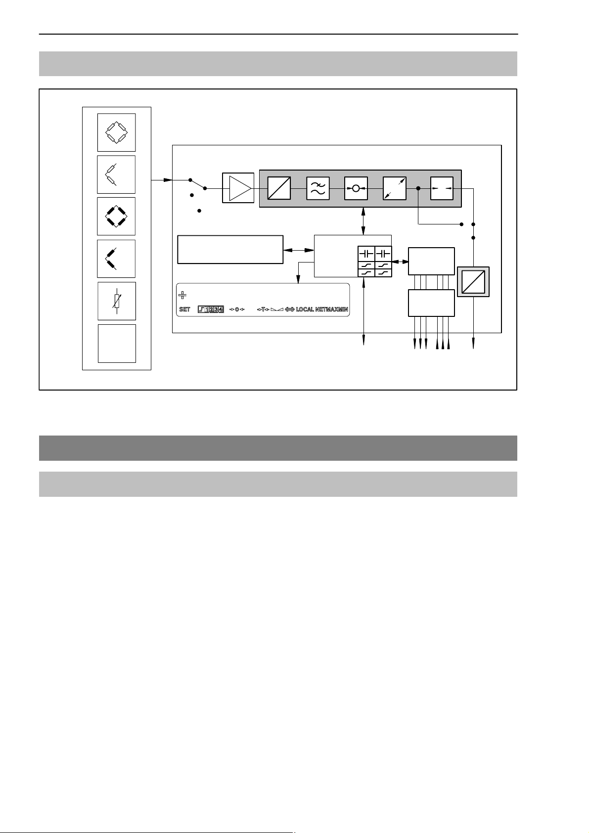
1.3 Block diagram
MVD2555
Measure
Zero
Cal.
Parameter memory
Data set 1...8
Connectable transducer
LVDT
Fig. 1.1 MVD2555 block diagram
2 Mounting
A
D
CPU
127,533 KN
PK-232 or
PK-485
E
Control
signals
Optical
coupler
5 outputs/
6 inputs
T
D
A
...
UA/IA
2.1 Pre-installation notes, factory settings
Before installing the device, check the parameters set at the factory, as the
elements for selecting the analogue output signal (current/voltage output) and
for setting synchronization, are located on the motherboard.
The factory settings are given below:
D Mains voltage: 230 V / 50 ... 60 Hz or 115 V / 50 ... 60 Hz, depending on
order
D Analogue output: output voltage "10 V
D Synchronization: Master
HBM A0104-5.6 en
MVD2555
11
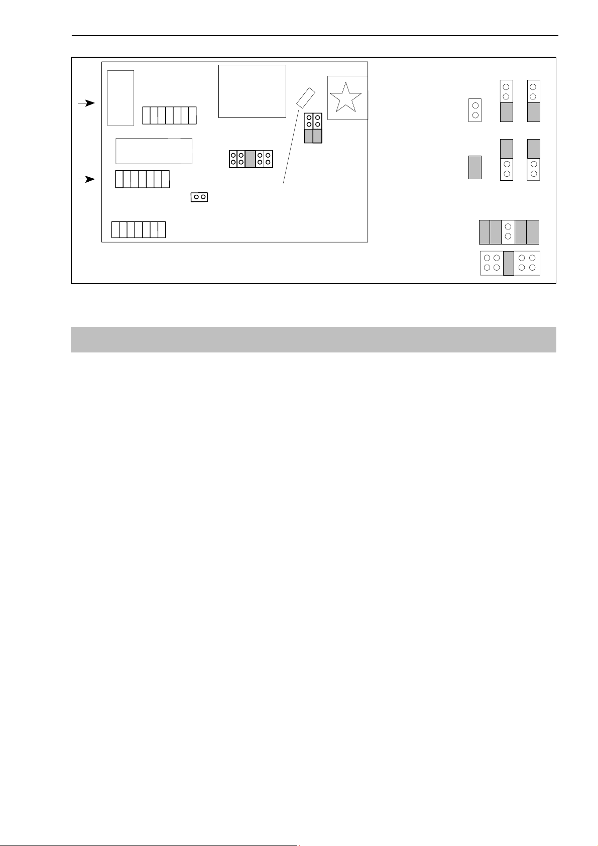
Master/Slave setting:
IC
Frontsite
ST100: for attaching spare bridges
ST9 and ST10:for options
ST9
IC
ST10
ST13
ST100
Transformer
ST11
Fuses (slow-blowing)
ST15
ST14
Fig. 2.1: Location of jumpers on motherboard
2.2 Changing the factory settings
To change the factory settings, proceed as follows:
Master:
Slave:
Current
Voltage
ST13
ST13 ST14 ST15
Analogue output:
ST11
ST11
ST14 ST15
D Loosen the four screws at the back of the housing.
D Carefully extract the back panel of the housing backward, with the
motherboard attached, until the jumper arrangement is accessible. You can
place a screwdriver between the connection board and the housing and
lever out the back panel.
D By following the diagram, change whichever setting is relevant to you with
the aid of the jumpers.
2.2.1 Setting the analogue output signal
To make the analogue output signal setting (voltage or current), use jumpers
ST11. Choose between "20 mA or 4 ... 20 mA in the control dialogue.
2.2.2 Choosing the operating mode for synchronization
To synchronize several devices, set one device as the Master. All the other
devices should then set to Slave. To make the ”Master” and ”Slave”
selections, use jumpers ST13, ST14 and ST15.
2.2.3 Replacing the fuses
To replace the fuse, remove the back panel of the housing as described. The
fuse (230 V/T63mA L; 115 V/T125mA L) will then be accessible on the
motherboard (see Fig. 2.1).
HBMA0104-5.6 en

12
MVD2555
2.3 Installing the amplifier in a panel-frame
The MVD2555 is designed to be installed in panel-frames, in accordance with
DIN43700.
Installation steps:
D Remove the fastening strap.
D Insert the housing into the cutout in the panel-frame from the front.
D Hang up the fastening strap on both sides and fasten it to the cutout with
the two threaded rods.
D Then connect the supply voltage and the transducer,
as shown in chapter 3.
partial section, front panel
+1
138
fastening strap
plastic frame
Fig. 2.2: Housing with fastening components
threaded rod
68
+0.7
HBM A0104-5.6 en
MVD2555
13
3 Connections
CAUTION
Before commissioning the device, please observe the safety instructions.
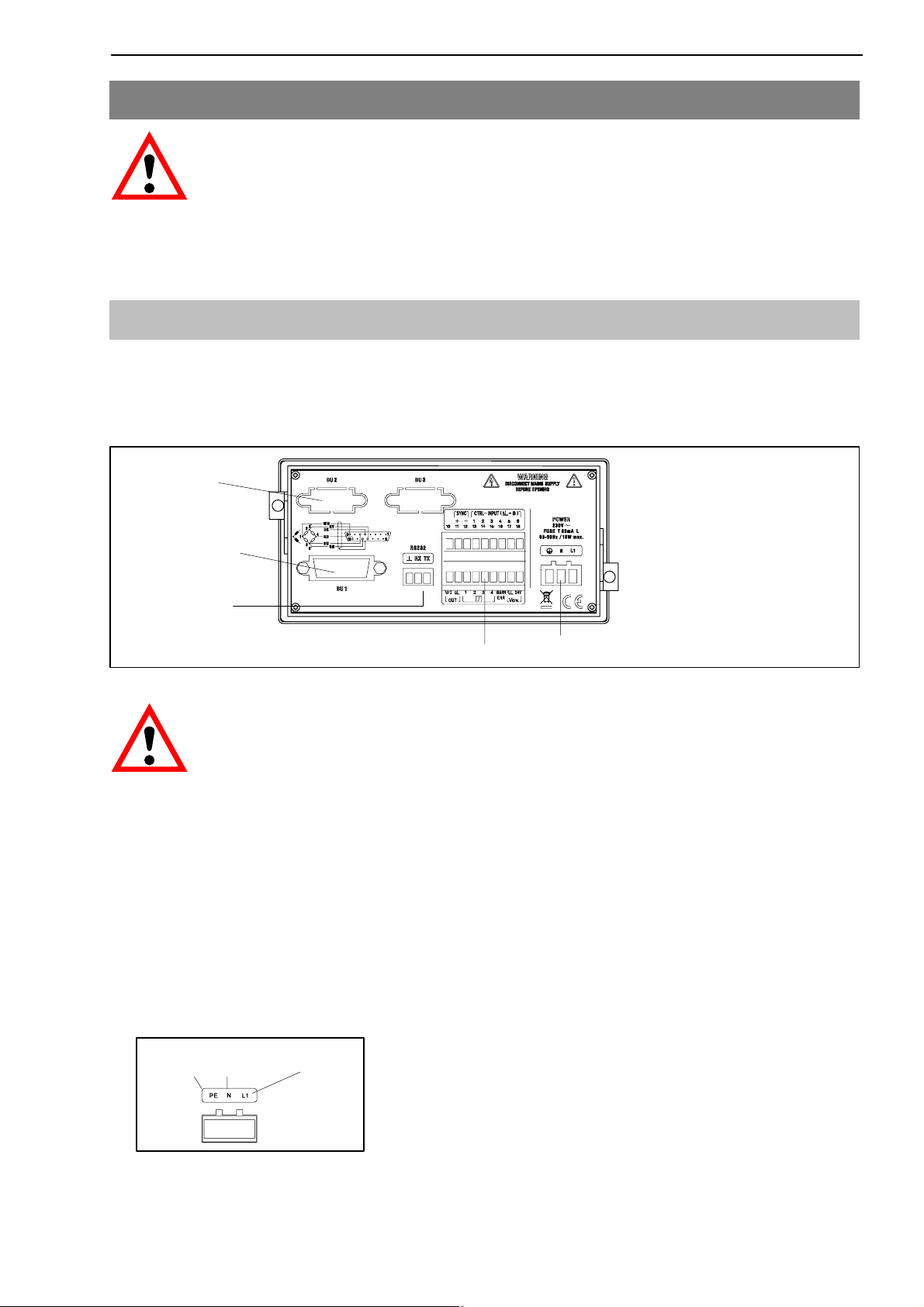
3.1 Connecting the voltage supply
Check that the mains voltage of the device (details on the back of the device)
matches the supply voltage. If this is not the case, please contact the appropriate HBM branch or HBM representative.
interface port
PK485
transducer
connection
(15-pin D-Sub
connector)
interface port
PK232
terminal strip for control inputs/outputs
terminal strip for mains connection
Fig. 3.1 Back of the device
CAUTION
As the device does not have a separate power switch, do not connect
the power cable directly to the mains. According to the VDE guideline,
there must be a switching device to disconnect the device from the
mains.
Connecting the mains cable:
D The cable must not be connected to the mains !
D Twist the wire ends of the mains cable and fit the end sleeves for strands
D Screw the wire ends to the terminal strip connector (3-pin)
earthed
conductor
neutral
Fig. 3.2: Pin assignment of the terminal strip connector (3-pin)
phase
D Plug the terminal strip connector (3-pin) into the mains connection socket
HBMA0104-5.6 en
14
MVD2555
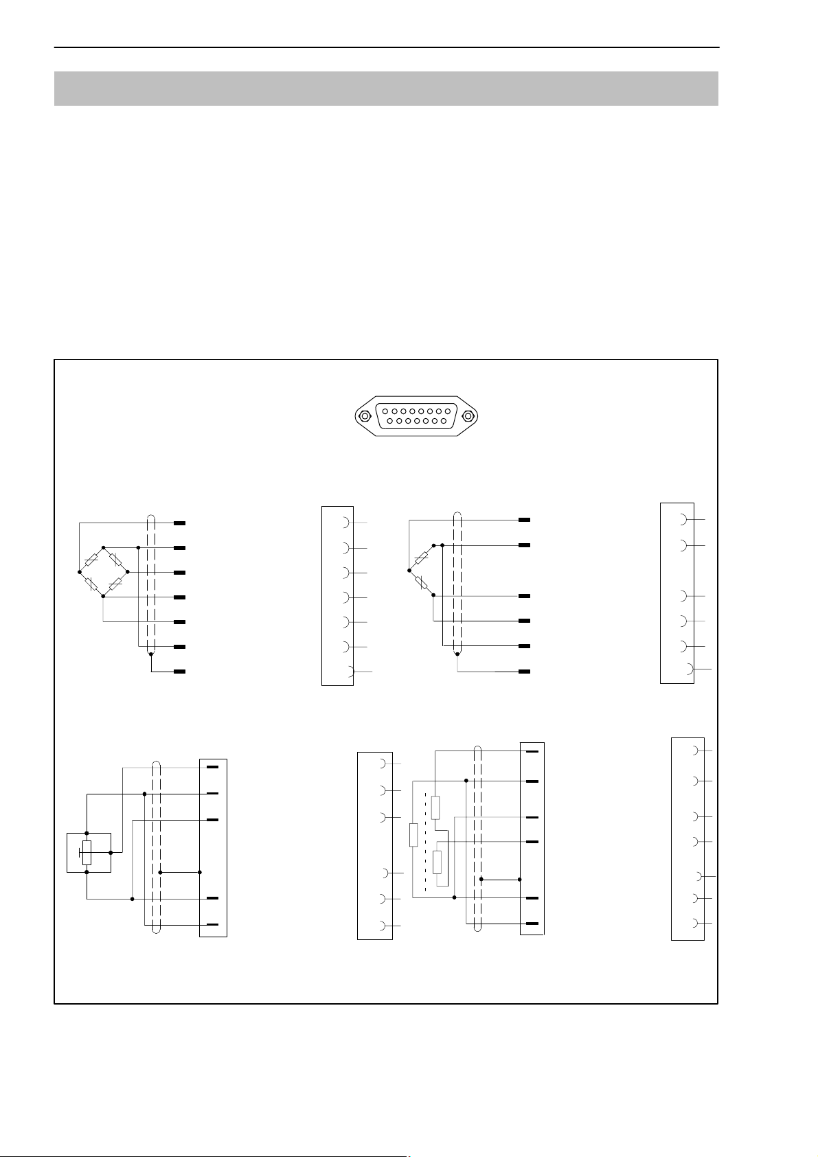
3.2 Connecting transducers
The following transducer types can be connected to the device:
D S.G. full and half bridge transducers
D Inductive full and half bridge transducers
D Potentiometric and piezoresistive transducers
D LVDT (Linear Variable Differential Transformer)
The connection is made using a 15-pin D-Sub connector on the back panel
of the housing, labelled BU1 (cable end connector: DB-15P,
Order No. 3-3312-0182).
BU 1
Transducer
connection socket
S.G. and inductive full bridges, piezoresistive transducers
Measurement
WH
signal (+)
BK
Voltage (-)
RD
Measurement
signal (-)
BU
Voltage (+)
GN
Sensor circuit (+)
GY
Sensor circuit (-)
YE
Cable shielding
Potentiometric transducer
Measurement
signal (+)
Voltage (-)
2
1
3
Voltage (+)
Cable shielding
Sensor circuit (+)
Sensor circuit (-)
8
5
15
6
13
12
Case
8
5
6
Case
13
12
8
15
1
9
S.G. and inductive half bridges
Measurement
WH
signal (+)
BK
Voltage (-)
BU
Voltage (+)
GN
Sensor circuit (+)
GY
Sensor circuit (-)
YE
Cable shileding
LVDT transducer
Measurement
signal (+)
Voltage (-)
Voltage (+)
Measurement
signal (-)
Cable shielding
Sensor circuit (+)
Sensor circuit (-)
8
5
6
13
12
Case
8
5
6
15
Case
13
12
Wire colors: WH= white; BK= black; BU= blue; RD= red; YE= yellow; GN= green; GY= gray
Fig. 3.3: Connecting different transducers
HBM A0104-5.6 en
MVD2555
15
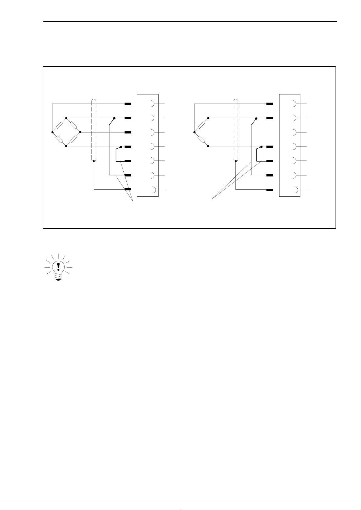
When connecting a transducer using four-wire technique, you must connect
the sensor circuits with the relevant bridge excitation circuit in the male cable
connector (pin 5 with pin 12 and pin 6 with pin 13).
Four-wire connection: full bridge
WH
BK
RD
BU
YE
Feedback bridges for four-wire connection
Wire colors: WH= white; BK= black; BU= blue; RD= red; YE= yellow; GN= green; GY= gray
8
5
15
6
13
12
Case
Four-wire connection: half bridge
WH
BK
BL
GN
GY
YE
Case
Fig. 3.4: Transducer connection in four-wire technique
8
5
15
6
13
12
NOTE
To connect the transducers, use HBM standard cable. If you use another
shielded, low-capacitance measurement cables, connect the shielding
of the transducer cable to the connector housing, in accordance with
HBM Greenline information (see http://www.hbm.com/Greenline). This
guarantees EMC protection.
HBMA0104-5.6 en
16
Á
Á
Á
Á
Á
Á
Á
Á
Á
Á
Á
Á
Á
Á
Á
Á
Á
Á
Á
Á
Á
Á
Á
MVD2555
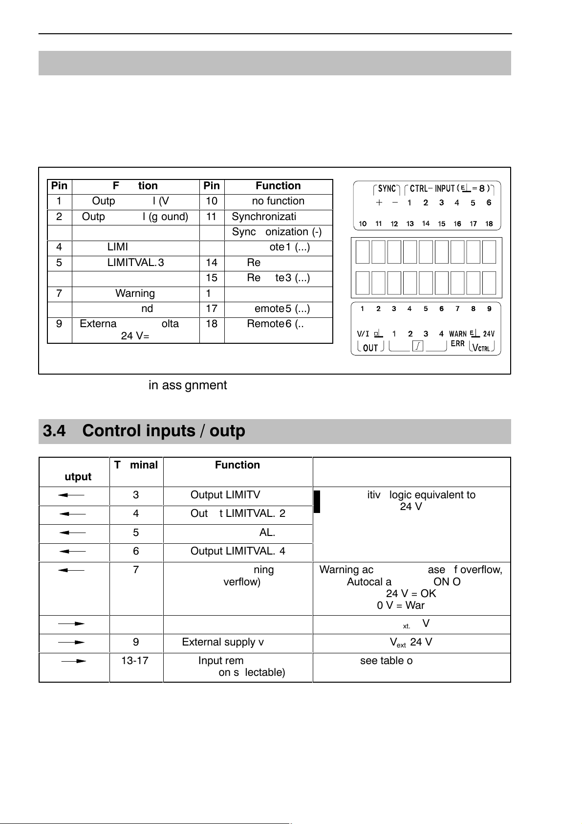
3.3 Analogue output
The analogue output signal is available as voltage ("10 V) or as current
("20 mA or 4 ... 20 mA) at terminals 1 and 2.
To choose current or voltage, use the jumpers on the amplifier motherboard,
as described in Chapter 2.1.
Pin
1
2
Output signal (ground)
3
ББББББББ
4
5
6
7
8
9
External supply voltage
Function
Output signal (V/I)
LIMITVAL.1
LIMITVAL.2
LIMITVAL.3
LIMITVAL.4
Warning
Ground
Pin
10
11
12
13
14
15
16
17
18
no function
Synchronization (+)
Synchronization (-)
БББББББ
Remote1 (...)
Remote2 (...)
Remote3 (...)
Remote4 (...)
Remote5 (...)
Remote6 (...)
24 V=
Fig. 3.5: Output pin assignment
3.4 Control inputs / outputs
Input/
Output
ÁÁÁÁ
Terminal
ÁÁ
Function
БББББББББ
Function
ББББББББББББ
3
4
ÁÁÁÁÁÁÁ
5
6
7
ÁÁÁÁ
ÁÁÁÁ
ÁÁÁÁÁÁÁ
ÁÁ
ÁÁ
8
9
13-17
ÁÁÁÁÁÁÁ
Output LIMITVAL. 1
Output LIMITVAL. 2
Output LIMITVAL. 3
БББББББББ
Output LIMITVAL. 4
Output warning
БББББББББ
БББББББББ
БББББББББ
(overflow)
Ground
External supply voltage
Input remote1-6
БББББББББ
(function selectable)
With positive logic equivalent to V
ext.
24 V
ББББББББББББ
Warning active in the case of overflow,
ББББББББББББ
ББББББББББББ
Autocal and MOTION OUT
24 V = OK
0 V = Warning
V
0 V
ББББББББББББ
ext.
V
24 V
ext.
see table on Page 47
ББББББББББББ
HBM A0104-5.6 en
MVD2555
17
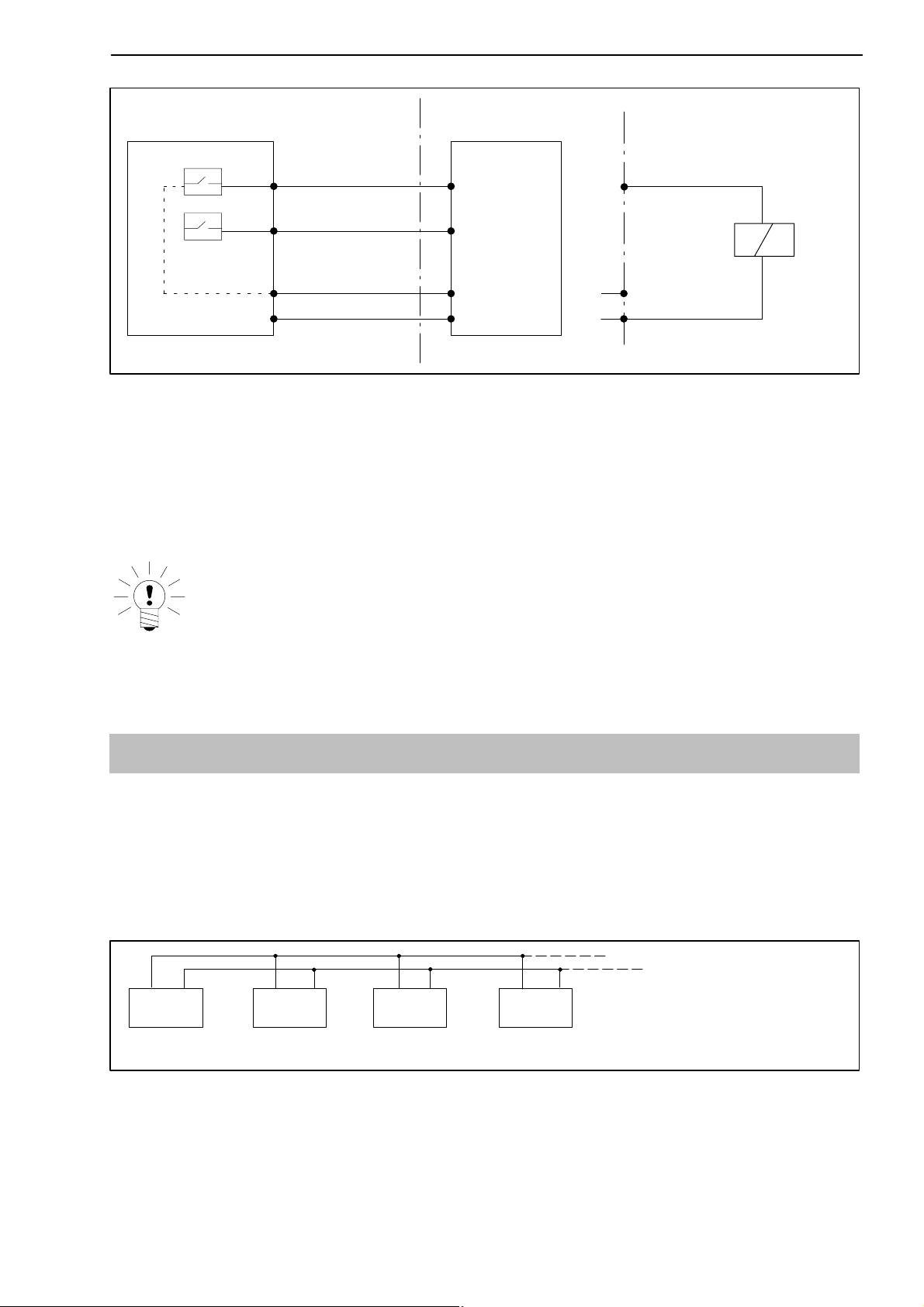
MVD2555
7
3
9
8
max. 0.5 A
24 V*
0 V*
PLC
Relay
max. 0.5 A
24 V*
0 V*
Fig. 3.6: Output assignments
The control inputs and outputs are available at the terminal strip socket
(9-pin) and are potential-separated by optical couplers.
* The control outputs and inputs must be supplied with an external voltage
(ground and 24 V).
NOTE
When the mains voltage is disconnected or fails and when the mains
fuse blows, all the control outputs are set to 0 V (V
ext.
).
3.5 Synchronization
If several devices are used right next to one another or if their cables run parallel, the devices should be synchronized. To achieve this, one device is set to
Master and all the others (max. seven) to Slave. The setup with jumpers on
the amplifier motherboard is described in Chapter 2.1. As well as these settings, the devices must be linked together for synchronization.
11 12 11 12 11 12 11 12
Master Slave Slave Slave
Device 1 Device 2 Device 3
Device 4 (...max. 7)
Fig. 3.7: Terminal connections for synchronization
HBMA0104-5.6 en
18
MVD2555
3.6 Setting the reading angle of the display
Depending on the mounting position, it may be possible to adjust the reading
angle. A potentiometer is used for this limited adjustment. The potentiometer
is located behind the keyboard under the display. To set a new viewing angle,
proceed as follows:
D Remove the plastic frame of the display from the housing.
D Carefully lever out the keyboard (e.g. with the aid of a screwdriver).
D Use a screwdriver to turn the potentiometer and set the optimum reading
angle.
D Put back the keyboard. Make sure that the plug is correctly threaded at the
bottom edge of the keyboard. Quickly test the keyboard by pressing a key.
If it functions correctly, you can continue.
D Insert and tighten the fastening screws.
D Push the plastic frame back on the housing.
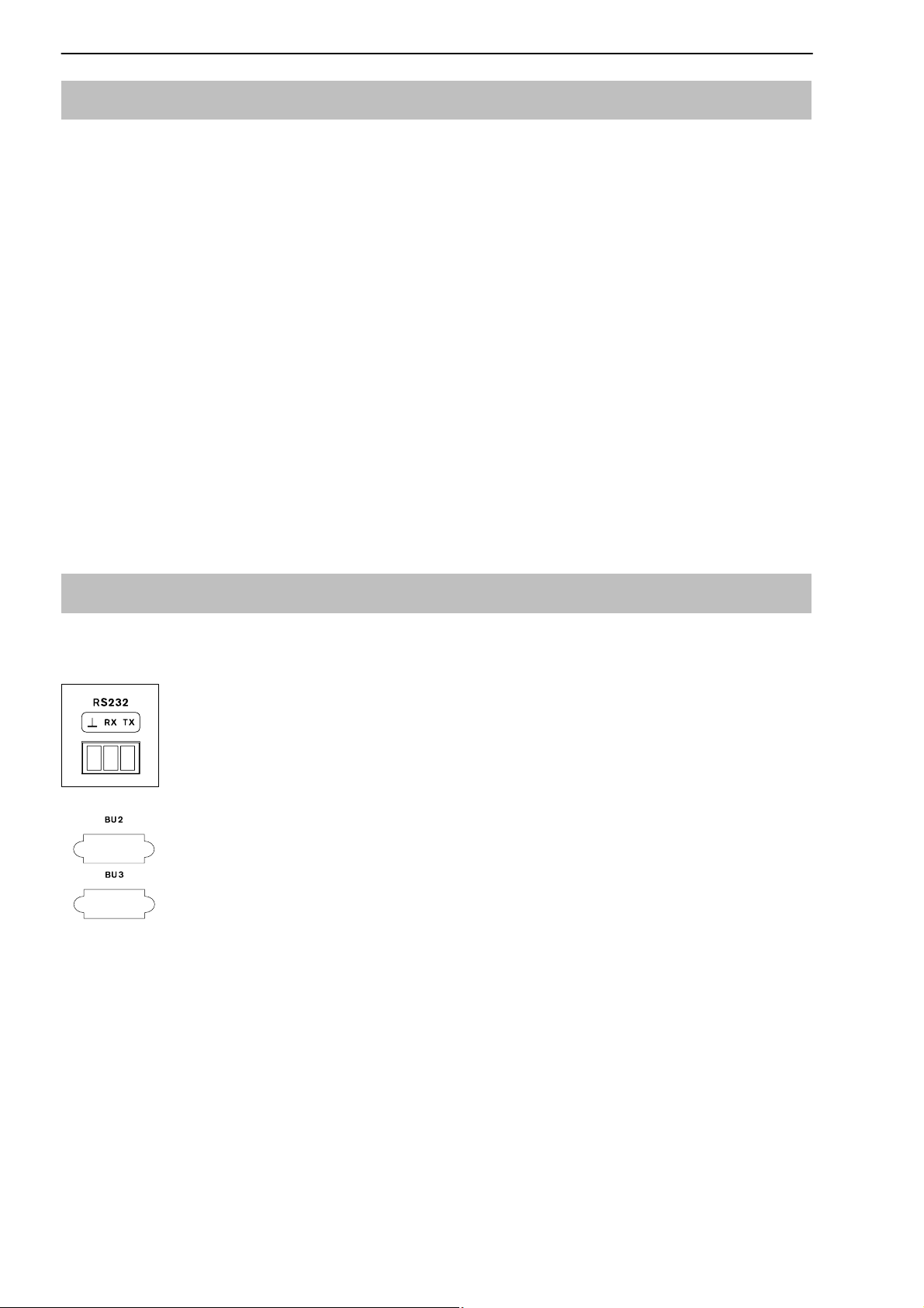
3.7 Connecting the serial interface
PK232-interface:
On the back of the device, there is anRS232 or RS485 serial
interface for connecting a computer or a terminal. The
PK485-interface is brought out at sockets Bu2 and Bu3.
When connecting a printer, a simple line printer needing no
RS485
When connecting a computer, it is possible to enter into dialogue with the
MVD2555. You can use control commands to make all the device settings and
query the measured values. An overview of the interface commands has been
compiled in another part of the Operating Manual ” Operating the MVD2555
by computer ”.
more than 4 seconds to print a line is sufficient. The printout
has 12 columns. This corresponds to a line length of 132
characters. Select the measured values to be printed as
described in Chapter 4.4.11.
HBM A0104-5.6 en

MVD2555
19
4 Setting up and operation
4.1 Commissioning and factory settings
Some of the steps you need to take to commission your measurement chain
(panel-frame amplifier and transducer) are listed below, so that you can carry
out an initial function test of all components. The description basically covers
adapting the MVD2555 to the transducer type to be used. We also warn about
certain errors which can typically occur during commissioning.
D Follow the steps given in the previous chapter to connect the mains cable
and the transducer to the measuring amplifier.
Please observe the safety instructions!
D Turn on the power switch.
D The device runs a function test and is then in measuring mode. Duration
of the function test: 1.5 s (if autocalibration is enabled, approx. 2.5 s).
During the function test, the warning output stays at 0 V. The factory
settings are active.
D Check the choice of output signal shown on the display. Use
the gross signal (no labelling in the display).
NOTE
If the error message CALERR. appears here, this can have the following
causes:
- No six-wire feedback connected
- Incorrect transducer/sensor connection
to select
- No transducer/sensor connected
Remedy:
Switch off the device. Connect the transducer properly. Switch the de-
vice back on.
HBMA0104-5.6 en

20
MVD2555
NOTE
If the error message “OVFL B, OVFL N,” appears, you must adjust the
amplifier for your type of transducer. The steps to take for each amplifier
are described below.
D To get from measuring mode to device setup mode, press
SET
for about
2 s. ”DIALOG” will appear in the display.
D Follow the examples given below to adjust the device to the connected
transducer type.
HBM A0104-5.6 en

MVD2555
Transducer types:
S.G. force transducer:
Adaptation: Example
Transducer type: Full bridge/2 mV/V=20 kN
Excitation: 2.5 V
Input: 4 mV/V
Calibration: Unit, nominal value/decimal point: 20.000 kN
Measuring range: 2 mV/V
Inductive displacement transducer:
Adaptation: Example
Transducer type: Half bridge, 10 mV/V
(80 mV/V)
Excitation: 1.0 V
Input: 10 mV/V (100 mV/V)
21
Calibration: Unit, nominal value/decimal point: 20.000 mm
Measuring range: 10 mV/V (80 mV/V)
Piezoresistive transducer:
Adaptation: Example
Transducer type: Half bridge
Excitation: 2.5 V
Input: 400 mV/V
Calibration: Unit, nominal value/decimal point: 30.000 bar
Measuring range: 200 mV/V
Potentiometric transducer:
Adaptation: Example
Transducer type: Half bridge
Excitation: 1 V
Input: 1000 mV/V
Calibration: Unit, nominal value/decimal point: 10.000 mm
Measuring range: 1000 mV/V
HBMA0104-5.6 en
 Loading...