

Page 1
Operating manual
Measurement amplifier
for panel mounting
MVD2510
A0125-4.0 en
Page 2

Page 3

MVD2510
Contents Page
1 Safety instructions 5..........................................
2 Scope of supply 11.............................................
3 Introduction 11.................................................
3.1 General 11.................................................
3.2 Block diagram 12............................................
4 Mounting 12...................................................
4.1 Read before mounting, factory setups 12.......................
4.2 Change factory setups 13....................................
4.2.1 Adjust analogue output signal 14.........................
3
4.2.2 Fuse replacement 14...................................
4.3 Insert unit plug-in strip 15.....................................
4.4 Install amplifier on control cabinet 16...........................
5 Electrical connection 17........................................
5.1 Connect voltage supply 17...................................
5.2 Connect transducers 19......................................
5.3 Analogue output, Control inputs/outputs 21.....................
6 Adjustments and operation 22..................................
6.1 Start-up and factory setups 22................................
6.2 Device operation and survey of keyboard functions 24...........
6.3 Functions in Measure mode 25................................
6.3.1 Adjust limit-value levels in the Measure mode 26...........
6.4 Programming mode 28.......................................
6.4.1 Change from the ”Measure” to the ”Programming” mode 29..
6.4.2 Programming 30.......................................
Operation in the Programming mode 30.........................
6.4.3 Change from the ”Programming” to the ”Measure” mode 31..
6.5 Information on groups and parameters 32......................
6.5.1 Dialog (dIAL) 32.......................................
A0125-4.0 en HBM
Page 4

4
1
MVD25
6.5.2 Load/Save in parameter set (PArA) 33....................
6.5.3 Calibration (CAL) 34....................................
6.5.4 Limit values (Li1, Li2) 35................................
6.5.5 Inputs and outputs (I_O) 37..............................
6.5.6 Additional function (InFO) 38............................
7 Example 39....................................................
8 Displays and ex-works settings 51...............................
9 Error messages 52.............................................
10 Keyword index 53..............................................
A0125-4.0 enHBM
Page 5

MVD2510
1 Safety instructions
Appropriate use
The MVD2510 with the connected transducers may be used for measurement
and directly related control and regulation tasks, only. Any other use is not
appropriate. To ensure safe operation, the transducer may only be used
according to the specifications given in this manual. It is also essential to
comply with the legal and safety requirements for the application concerned
during use. The same applies to the use of accessories.
Each time, before starting up the equipment, you must first run a project
planning and risk analysis that takes into account all the safety aspects of
automation technology. This particularly concerns personal and machine
protection.
Additional safety precautions must be taken in plants where malfunctions
could cause major damage, loss of data or even personal injury. In the event
of a fault, these precautions establish safe operating conditions.
5
This can be done, for example, by mechanical interlocking, error signaling,
limit value switches, etc.
WARNING
Due to the fact that the device has not been equipped with a proper mains
switch, the supply cable must not be connected directly to the mains. VDE
guidelines require that the device can be disconnected from the mains via a
switching device (double-break disconnector). It is essential that the disconnector is labeled accordingly and easy to access and operate by the user.
Before connecting the device, make sure that the mains voltage and current
type specified on the name plate correspond to the mains voltage and current
type at the site of installation and that the current circuit used is sufficiently
safe.
Devices designed for panel mounting may only be operated in an EMC-tested
control cabinet. (see page LEERER MERKER).
The device complies with the safety requirements of DIN EN 61010-part1
(VDE 0411-part1); protection class I.
HBMA0125-4.0 en
Page 6

6
General dangers in the case of non-observance of the safety
instructions
The MVD2510 complies with the state of the art and is operationally reliable. If
the device is used and operated inappropriately by untrained personnel,
residual dangers might develop.
Any person charged with device installation, operation, maintenance or repair
must in any case have read and understood the operating manual and the
safety instructions, in particular.
Conditions on site
− Protect the device from direct contact with water.
− Protect the PMX system from moisture and humidity or weather conditions
such as rain, snow, etc. The degree of protection per EN 60529 standard is
IP 40 (device as a whole); IP51 (front, membrane keypad)
− Do not expose the device to direct sunlight.
MVD2510
− Please observe the permissible maximum ambient temperatures stated in
the specifications.
− The permissible relative humidity at 31 °C is 95 % (non condensing); linear
reduction to 50 % at 40 °C.
− It is safe to operate the MVD2510 system up to a height of 2000 m.
− Mounting in an EMC-tested control cabinet with line filter (see page
LEERER MERKER).
Maintenance and cleaning
MVD2510 devices are maintenance-free. Please note the following points
when cleaning the housing:
− Withdraw the mains plug from the socket before carrying out any cleaning.
− Clean the housing with a soft, slightly damp (not wet!) cloth. You should on
no account use solvent, since it may damage the labelling on the front
panel and the indicator box.
− When cleaning, ensure that no liquid gets into the device or connections.
Residual dangers
The MVD2510’s scope of performance and supply covers part of the
measuring-technology, only. The plant designer/constructor/operator must in
addition design, realise and take responsibility for the measuring-system’s
safety such that potential residual dangers are minimized. The respective
regulations must in any case be observed. Residual dangers regarding the
measuringsystem must be specified explicitly.
HBM A0125-4.0 en
Page 7

MVD2510
Product liability
In the following cases, the protection provided for the device may be ad
versely affected. Liability for device functionality then passes to the operator:
− The device is not used in accordance with the operating manual.
− The device is used outside the field of application described in this
Chapter.
− The operator makes unauthorized changes to the device.
Warning signs and danger symbols
Important instructions for your safety are specifically identified. It is essential
to follow these instructions in order to prevent accidents and damage to prop
erty.
7
Safety instructions are structured as follows:
SIGNAL WORD
Type of danger
Consequences of non-compliance
Averting the danger
− Warning sign: draws your attention to the danger
− Signal word: indicates the severity of the danger
(see table below)
− Type of danger: mentions the type or source of the danger
− Consequences: describes the consequences of non-compliance
− Defense: indicates how the danger can be avoided/bypassed
HBMA0125-4.0 en
Page 8
8
Danger class according to ANSI
Warning sign, signal word Significance
This marking warns of a potentially dangerous
WARNING
CAUTION
NOTE
situation in which failure to comply with safety
requirements can result in death or serious
physical injury.
This marking warns of a potentially dangerous
situation in which failure to comply with safety
requirements can result in slight or moderate
physical injury.
This marking draws your attention to a situation in
which failure to comply with safety requirements
could lead to damage to property.
MVD2510
On the module
Meaning: Take details in the operating manual into account
On the module
Meaning: Disconnect mains supply before opening
On the module
Meaning: CE mark
The CE mark is used by the manufacturer to declare that the product com
plies with the requirements of the relevant EC directives (the Declaration of
Conformity can be found at http://www.hbm.com/HBMdoc
).
On the module
Meaning : Statutory waste disposal mark
The electrical and electronic devices that bear this symbol are subject to the
European Waste Electrical and Electronic Equipment Directive 2002/96/EC.
HBM A0125-4.0 en
Page 9

MVD2510
The symbol indicates that the device must not be disposed of as household
garbage.
In accordance with national and local environmental protection and material
recovery and recycling regulations, old modules that can no longer be used
must be disposed of separately and not with normal household garbage.
If you need more information about waste disposal, please contact your local
authorities or the dealer from whom you purchased the product.
As waste disposal regulations within the EU may differ from country to coun
try, we ask that you contact your supplier as necessary.
Working safely
Note
9
Due to the fact that the device has not been equipped with a proper mains
switch, the supply cable must not be connected directly to the mains. VDE
guidelines require that the device can be disconnected from the mains via a
switching device (double-break disconnector). It is essential that the
disconnector is labeled accordingly and easy to access and operate by the
user.
The supply connection, as well as the signal and sense leads, must be
installed in such a way that electromagnetic interference does not adversely
affect device functionality (HBM recommendation: ”Greenline shielding
design”, downloadable from the Internet at http://www.hbm.com/Greenline
).
Automation equipment and devices must be covered over in such a way that
adequate protection or locking against unintentional actuation is provided
(such as access checks, password protection, etc.).
When devices are working in a network, these networks must be designed in
such a way that malfunctions in individual nodes can be detected and shut
down.
Safety precautions must be taken both in terms of hardware and software, so
that a line break or other interruptions to signal transmission, such as via the
bus interfaces, do not cause undefined states or loss of data in the
automation device.
HBMA0125-4.0 en
Page 10

10
MVD2510
Reconstruction and modifications
HBM’s express consent is required for modifications regarding the MVD2510’s
construction and safety. HBM does not take responsibility for damage
resulting from unauthorized modifications.
In particular, repair and soldering works on the boards are prohibited. If
complete componentry is replaced use original HBM components, only.
The product is delivered from the factory with a fixed hardware and software
configuration. Changes can only be made within the possibilities documented
in the manuals.
Qualified personnel
Qualified personnel means persons entrusted with siting, mounting, starting
up and operating the product, who possess the appropriate qualifications for
their function (qualified electrician, or by someone with electrical training un
der the supervision of a qualified electrician).
This device is only to be installed and used by qualified personnel strictly in
accordance with the specifications and with the safety rules and regulations
which follow.
This includes people who meet at least one of the three following require
ments:
− Knowledge of the safety concepts of automation technology is a
requirement and as project personnel, you must be familiar with these
concepts.
− As automation plant operating personnel, you have been instructed how to
handle the machinery and are familiar with the operation of the equipment
and technologies described in this documentation.
− As commissioning engineers or service engineers, you have successfully
completed the training to qualify you to repair the automation systems.
You are also authorized to activate, to ground and label circuits and
equipment in accordance with safety engineering standards.
It is also essential to comply with the legal and safety requirements for the ap
plication concerned during use. The same applies to the use of accessories.
Important
The safety instructions are also included in paper format with the product
("Documentation and Safety instructions PMX" A3260-2.0).
HBM A0125-4.0 en
Page 11

MVD2510
2 Scope of supply
The scope of supply includes:
D MVD2510 device with two threaded fastening screws
D MVD2510 operating manual incl. a questionnaire
D 15-pin D-plug for transducer connection
D Unit plug-in strip
D 1 terminal-strip plug (9 pins) for connection of the control inputs and
outputs, 1 terminal-strip plug (3 pins) for mains connection
3 Introduction
11
3.1 General
The MVD2510 amplifier for panel mounting (to DIN 43 700) enables
measurements from strain-gauge transducers used for industrial weighing
(not legal for trade) applications to be acquired and processed.
Main characteristics:
D Transducers that may be connected: S/G full bridges
D 4 1/2-digit LED display ("19999 Digits) and various special characters
D Operation via foil-type keyboard; single keys can be locked
D 2 limit-value switches
D Control inputs and outputs (electrically isolated by optocouplers)
HBMA0125-4.0 en
Page 12
12
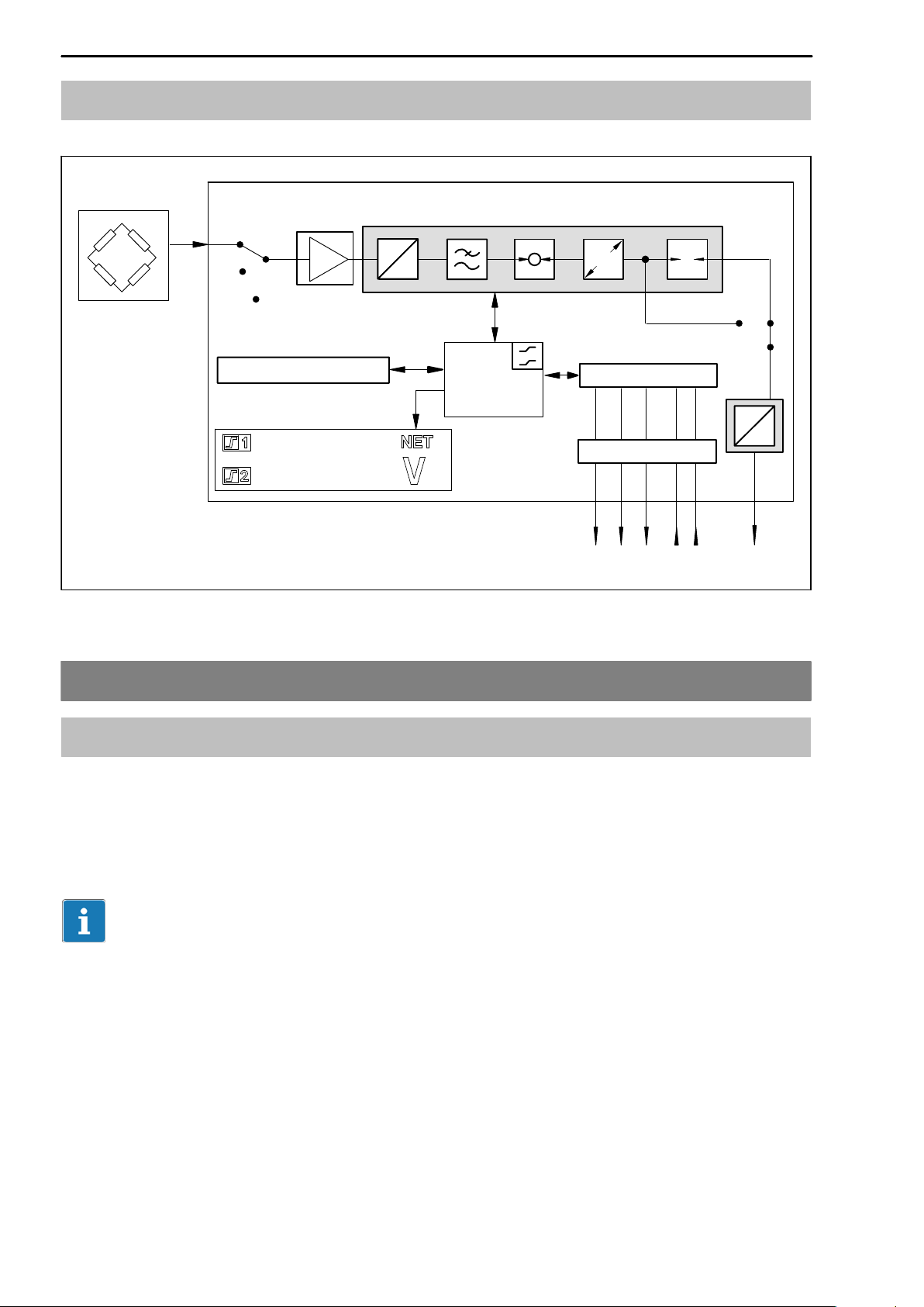
3.2 Block diagram
Measure
MVD2510
Zero
Cal.
Transducers that
may be connected
Parameter memory
+18.750
Fig. 3.1 MVD 2510 block diagram
4 Mounting
A
D
CPU
E
Control signals
Optocoupler
3 out-/2 inputs
T
D
A
UO/I
O
4.1 Read before mounting, factory setups
Before installing the MVD2510 panel amplifier, check the parameters that
have been adjusted at the factory, because the elements required for the
selection of the analogue output signal (current/voltage output) are located on
the board.
Important
The device must be mounted in an EMC-tested control cabinet with line filter
(see page LEERER MERKER).
Factory setup:
D Mains voltage: 230 V / 50...60 Hz or 115 V / 50..60 Hz according to your
order
D Analogue output: Output voltage "10 V
HBM A0125-4.0 en
Page 13

MVD2510
13
4.2 Change factory setups
Select analogue output signal
To change the factory setup proceed as follows:
1 Slacken the four screws on the housing rear.
2 Carefully pull off to the back the housing rear and the board until the jumper
arrangement is accessible. For this purpose, introduce a screw driver
between connection plate and housing to lift off the device back panel.
3 Use the plug bridges to change the desired setups according to
Fig. 4.2.
4 Insert housing rear and fasten with screws.
2
Pull
backwards
1
Plug-on jumpers ac-
3
cording to fig. 3
Slacken
screws (4x)
Fig. 4.1: Change factory setup
HBMA0125-4.0 en
Page 14
14
MVD2510
4.2.1 Adjust analogue output signal
Change the position of jumper ST5 to select the analogue output signal
(voltage or current), see Fig. 4.2. Enter the dialog mode to select "20 mA or
4...20 mA respectively.
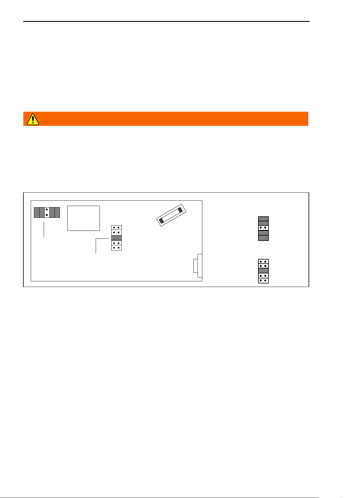
4.2.2 Fuse replacement
WARNING
Disconnect the device from the mains supply before opening the MVD2510.
To replace the fuse you have to take off the device rear as described above.
Then, the fuse (230 V/100 mA; 115 V/200 mA) on the board will be accessible
(lift off transparent cap).
Transformer
Fuse
Spare jumpers
Jumper
Fig. 4.2: Position of the jumper and fuse on the board
Analogue output:
Current
ST5
Voltage:
ST5
HBM A0125-4.0 en
Page 15
MVD2510
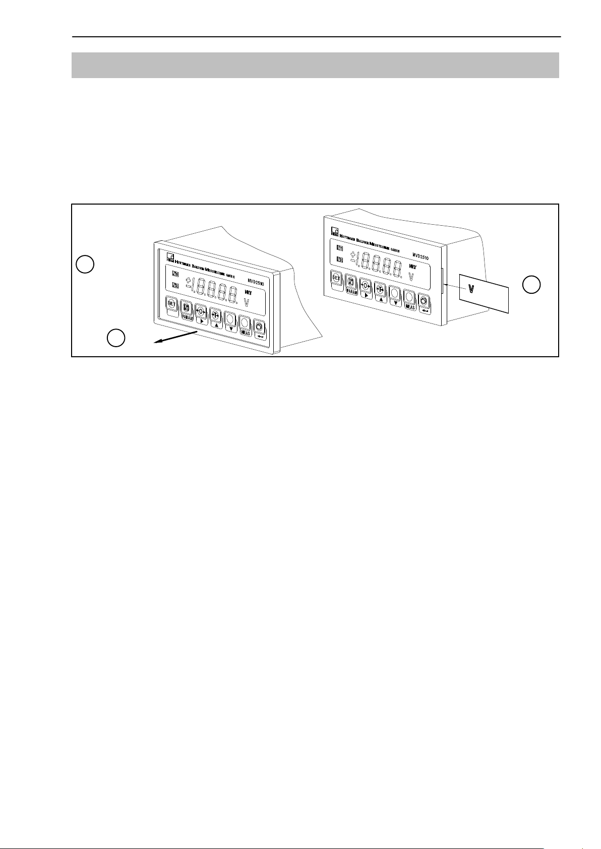
4.3 Insert unit plug-in strip
The unit for display is defined by ready-made plug-in strips that are supplied
with the device.
1 Remove the display’s plastics frame.
2 Insert the required strip into the appropriate cutout.
3 Re-install the plastics frame on the housing.
Insert
unit plug-in strip
1
15
Remove/reinstall
plastics frame
3
2
HBMA0125-4.0 en
Page 16
16
MVD2510
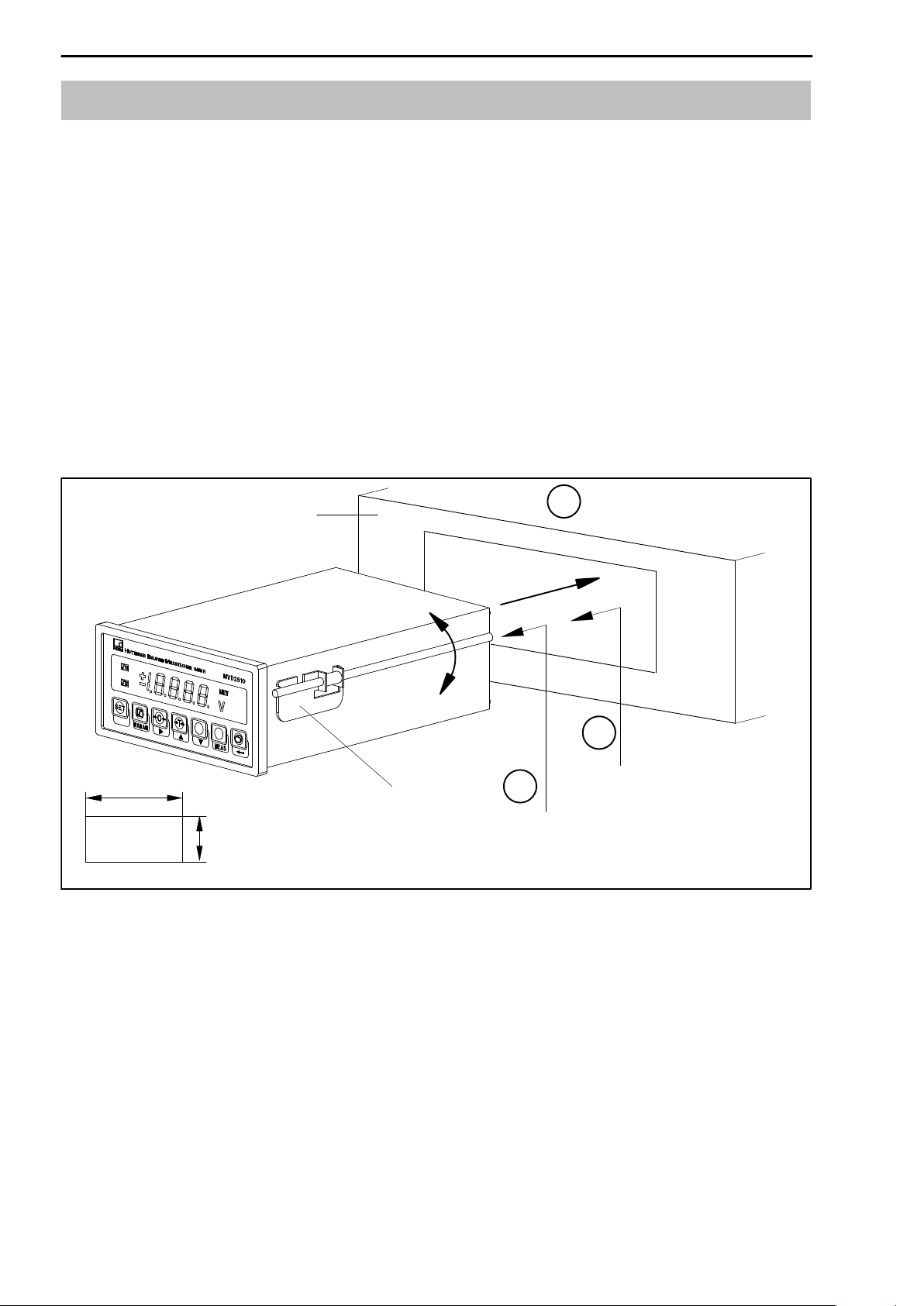
4.4 Install amplifier on control cabinet
The MVD2510 has been designed for panel mounting according to
DIN43 700.
Install amplifier on panel:
1 Turn fastening bow downwards and remove it from housing.
2 Insert housing into panel cutout from the front.
3 Hook in fastening bow on both sides, turn upwards and screw-fasten with
the two threaded rods on the cutout.
4 Then connect the supply voltage to the transducer as described in
chapter 4.
Panel
+1
138
Fastening bow
+0.7
68
Front panel cutout
Fig. 4.3 Install housing on panel
2
1
Hook out
threaded rod
Insert housing into panel
cutout
3
Hook in fastening bow
and screw fasten
HBM A0125-4.0 en
Page 17
MVD2510
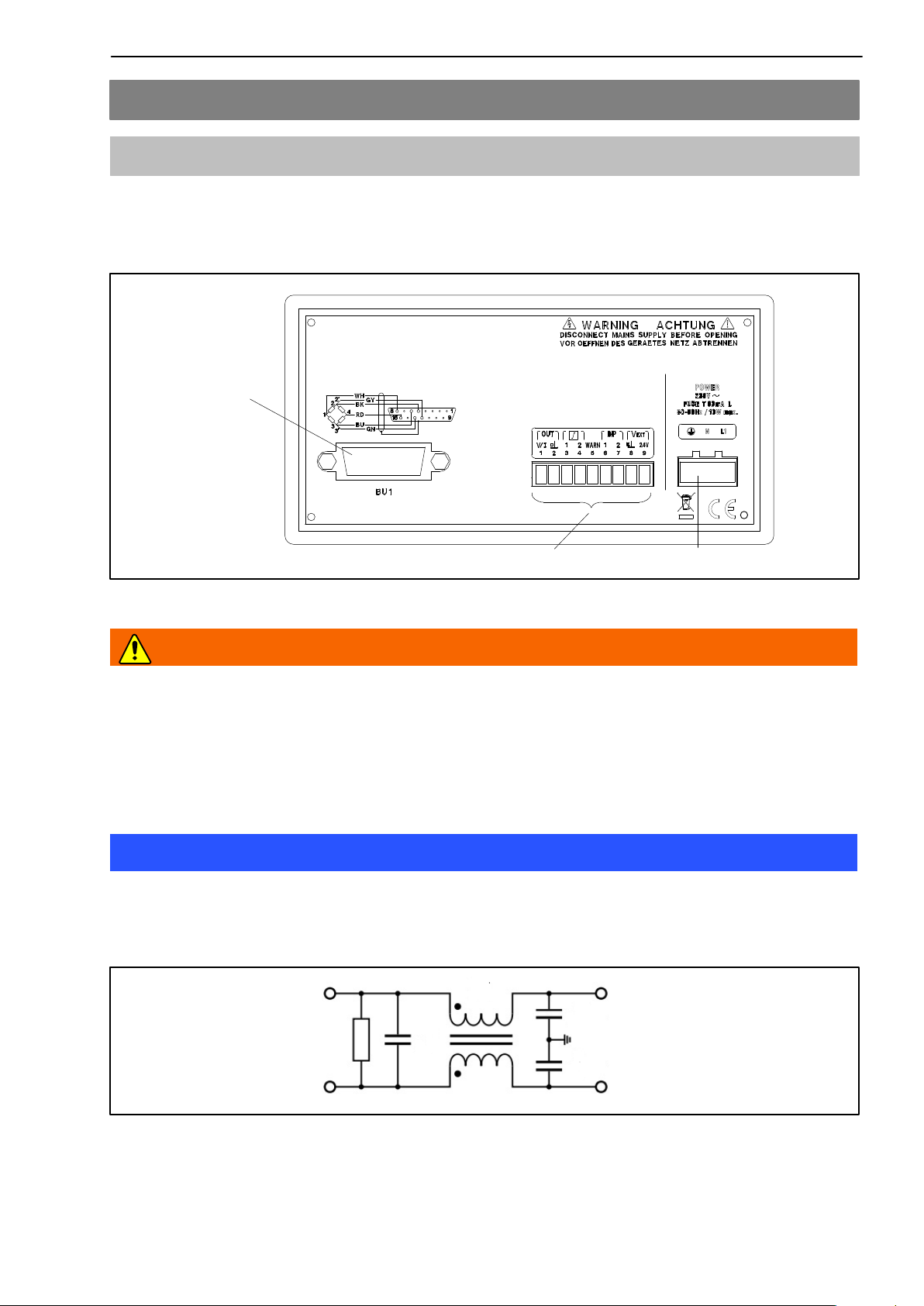
5 Electrical connection
5.1 Connect voltage supply
Compare the device’s mains voltage (specified on device rear) to the supply
voltage. If they are not identical, contact your HBM representative.
Transducer-
Transducerconnection
connection
(15-pin D-plug)
(15-pin D-plug)
17
9-pin terminal-strip socket
Fig. 5.1: Device rear
3-pin terminal-strip socket
WARNING
Due to the fact that the device has not been equipped with a proper mains
switch, the connected supply cable may not be connected to mains directly.
According to a VDE recommendation the device must be equipped with a
switching device that can be disconnected from the mains supply.
Note
Ensure that the device is installed in an EMC-tested control cabinet and
connected to a suitable mains filter, e.g. a single-stage filter,
1 ampere with the following structure:
LINE LOAD
HBMA0125-4.0 en
Page 18

18
MVD2510
Mounting of the line filter:
Make sure that the line filter is laid out flat on the inside of the control cab-
inet and that the connecting cables are led directly to the filter’s input connectors.
The filter is laid out flat on the control cabinet.
The contact area needs to be clean and blank.
For more information please refer to the mounting instructions provided by the
manufacturer of the control cabinet.
Connect mains cable:
D Connection to the power supply may only be made in the de−ener-
gized state !
D Use end sleeves for the mains cable’s core ends or twist them.
D Screw the core ends onto the terminal-strip connector (3 pins)
Protective
earth wire
Fig. 5.2: Assignment of terminal strip connector (3−pole)
Neutral
wire
Phase
D Connect terminal-strip connector (3 pins) to mains-connection socket
Note
It is essential that the cables are suitable for the mains voltage. Between the
connectors of the nine- and three-pin terminals, appropriate measures need to
be taken to prevent disturbance voltages. Ensure separate cable routing
between sensor connector (A), signal output (B) and voltage supply (C).
A
HBM A0125-4.0 en
B
C
Page 19

MVD2510
19
5.2 Connect transducers
The MVD2510 enables S/G full-bridge transducers to be connected via a
15-pin D-plug designated BU1 on the housing rear. See the below figures for
the connection diagram.
Six-wire connection
WH
BK
RD
BU
GN
GY
YE
Four-wire connection
WH
BK
RD
BU
8
5
15
6
13
12
Hous
8
5
15
6
Meas. signal (+)
Bridge excitation voltage (−)
Meas. signal (−)
Bridge excitation voltage (+)
Sensor line (+)
Sensor line (−)
.
Cable screen
Use HBM standard cable for transducer
connection. When using other screened,
low-capacitance cable types connect the
transducer cable screen to the plug housing
according to the HBM Greenline information,
thus ensuring optimum EMC protection.
NOTE
BU 1
Transducer
connection-socket
8
15
1
9
13
12
YE
Feed-back bridges in the transducer
Cable-core colours: WH= white; BK= black; BU= blue; RD= red; YE=yellow; GN= green;
GY= grey
Hous
.
Fig. 5.3 Transducer connection
HBMA0125-4.0 en
Page 20

20
Transducer 1
Transducer 2
.
.
.
4 transducers
maximum
ye
ye
gy
gy
gn
gn
bu
bu
rd
rd
bk
bk
wh
wh
MVD2510
Route the two cable
cores together as
close as possible to
the transducer
wh
bk
rd
bu
gn
8
5
15
6
13
gy
80 ... 5000
ye
12
Geh
Cable core colours: wh=white; bk=black; bu=blue; rd=red; ye=yellow; gn=green;
gy=grey.
Fig. 5.4: Connection of parallel−wired transducers
.
HBM A0125-4.0 en
Page 21

MVD2510
21
5.3 Analogue output, Control inputs/outputs
The analogue output signal is present at terminals 1 and 2 as voltage ("10 V)
or current (0..."20 mA or +4...+20 mA).
Use the plug bridges (jumpers) on the amplifier board to select current/voltage
as described in chapter 3.2.1.
Refer to the below table
for the terminals 1 to 9
Analogue output signal
Input/Out-
put
Terminal
1
2
3
4
5
6
7
8
9
Function
Output signal (V/I)
Output signal (ground)
Output limit-value1
Output limit-value2
Output Warning (Overflow)
Input control-contact1
(Function selectable)
Input control-contact2
(Function selectable)
Ground (control outputs)
Supply voltage (control
outputs)
"10 V,"20 mA; +4.. 20 mA
With positive logic corresponding to
24 V
V
ext.
Warning active for overflow and
autocal.
24 V = OK
0 V = Warning
see table on page 38
V
0 V
ext.
V
24...30 V*
ext.
Note
The connections of the analog output voltage or current must be shielded .
and the shielding must be connected to an EMC-tested control cabinet.
The connection cables of the I/Os (Warning, LIV 1/2, INP 1/2, Ground, V
ext.
must not be longer than 30 m and may be laid only inside closed buildings.
)
HBMA0125-4.0 en
Page 22

22
MVD2510
MVD2510 PLC
3
9
8
Fig. 5.5: Output configuration
max. 0,5 A
4
24 V*
0 V
External supply voltage for control
Relay
max. 0,5 A
24 V*
0 V
outputs
WARNING
The control inputs and outputs on the terminal-strip socket (9 pins) are electrically isolated by optocouplers. The control outputs must be supplied with an
external DC voltage (ground and 24 V) and must have protective separation
from the mains (safety extra low voltage as per EN 61140 and IEC 61140 respectively; safety transformers as per EN 6155826 and IEC 6155826 respectively).
6 Adjustments and operation
6.1 Start-up and factory setups
Below we have listed some steps to be taken before starting up your
measuring system (panel amplifier and transducer) and to enable a first
functional test for all components to be made. This section mainly describes
the adaptation of the MVD2510 to the transducer type used. In addition, some
errors are mentioned that typically occur during device start-up.
D Install the device on your panel (see page 16)
D Proceed as described in chapter 4 to connect the mains cable and the
transducer to the panel amplifier.
CAUTION
Observe the safety instructions!
HBM A0125-4.0 en
Page 23

MVD2510
D Connect the device to mains via an external switching device (mains
switch).
D The device makes a functional test and then enters measure mode. The
factory setups are activated.
Ex-works setting: The measurement range is set to a sensitivity of 2 mV/V
and a display full−scale value of 10000 digits (see table on page 51).
SET
D Press
. The ex-works setting is loaded.
Note
If the OFL error message is displayed, this may have the below reasons:
23
− No six-wire feedback line connected
− Transducer/sensor not connected correctly
− No transducer/sensor connected
Remedy: Switch device off. Connect the transducer correctly. Switch device
on again.
D Use the
key to select the gross signal (NET is not displayed).
The device is now ready for operation. Carry out your settings, following
Chapters 5 and 6.
HBMA0125-4.0 en
Page 24

24
MVD2510
6.2 Device operation and survey of keyboard functions
The operating concept differentiates between two types of key functions:
− keys that are effective during the measurement mode and
− keys that are effective in the programming mode.
Each function key for Measure mode can be locked individually to prevent
undesired key operation (see page 33).
Here also, a password may be entered to prevent undesired modifications.
Interchangeable
unit symbols
Measurement
display,
Parameter
display
Mode line
SET
Change
operating
mode
SET
Adjust
limit-
value level
Measure mode
TareZero
Programming mode
MVD2510
Change
display
Change
operating
mode (2sec)/
Select group
HBM A0125-4.0 en
Parameter
selection
Display
adjusted
value/Select
digit
parameters/Change
Select
digit
Measure
input
signal
Confirm
Page 25

MVD2510
6.3 Functions in Measure mode
If necessary, all keys/functions in Measure mode may be locked to prevent
unauthorized manipulation.
Key Meaning
25
SET
Permits to change from the Measure to the Programming mode
(and vice versa) when pressed for about 2 sec.
Enables the limit-value levels (LIV1, LIV2) to be adjusted (see
next page). The other limit-value parameters such as hysteresis,
direction etc. are not changed. To enable changes to the
limit-value level use LIV1,2/(b.Li) key (see page 33).
Is used for system zero-balance (also possible with control
contact).The signal present at the input is taken as zero point.
Starts taring(also possible with control contact).
The currently present measurement is used as tare value.
Changes measurement display between:
Gross value no display identification
Net value ”NET” is displayed
HBMA0125-4.0 en
Page 26

26
6.3.1 Adjust limit-value levels in the Measure mode
There are two possibilities for the selection of the limit-value level:
a) Enter numerical value for limit-value levels (Li)
Li1L (Limit value 1)
The limit-value level entered last will
be displayed.
The first number flashes. If LOCK appears, the limit level is blocked.
Adjust the desired value
MVD2510
Save changes buffered against mains
failure
Confirm
Li2L (Limit value 2)
The limit-value level entered last will
be displayed.
The first number flashes. If LOCK appears, the limit level is blocked.
Adjust the desired value
Confirm
Do not save changes buffered against
mains failure
SET
SET
HBM A0125-4.0 en
Press 2 sec,
STOR will be displayed
dOnE will be displayed
Li1L and Li2L are saved buffered against mains
failure; the device changes to the Measure mode
SET
SET
Press 2 sec,
STOR will be displayed
The device changes
to the Measure mode
Page 27

MVD2510
b) Accept signal present at the input as limit-value level
Li1L (Limit value 1)
The limit-value level entered last will
be displayed.
27
Save changes buffered against mains
failure
MEAS
The signal present at the input will be
displayed
Confirm. The applied input signal is
accepted as the limit level.
Li1L (Limit value 2)
The limit-value level entered last will
be displayed.
MEAS
The signal present at the input will be
displayed
Confirm. The applied input signal is
accepted as the limit level.
Do not save changes buffered against
mains failure
SET
SET
Press 2 sec,
STOR will be displayed
dOnE will be displayed
Li1L and Li2L are saved buffered against mains
failure; the device changes to the Measure mode
SET
SET
Press 2 sec,
STOR will be displayed
The device changes
to the Measure mode
HBMA0125-4.0 en
Page 28

28
MVD2510
6.4 Programming mode
In the Programming mode and 2 are flashing alternately.
This Operating mode enables all amplifier setups required for your application
to be made. The parameters are grouped and codes are used for the group
names.
Meaning of the keys:
Change operating mode, select group (e.g. CAL)
SET
PAR
Parameter selection (e.g. INdc)
The below three keys enable numerical values to be displayed
or entered.
To display the value adjusted last. Press the key to select the
desired digit.
To change the digit in ascending sequence.
To change the digit in descending sequence.
Measures input signal.
MEAS
Confirms entry/change.
HBM A0125-4.0 en
Page 29

MVD2510
6.4.1 Change from the ”Measure” to the ”Programming” mode
29
D Press
SET
for approx. 2 s.
The device changes from the ”Measure” to the ”Programming” mode if the
password is 0000. This applies for the factory setup; dIAL will be displayed.
If a password has already been entered (different from 0000), then CodE
appears in the display on changing to ”Program”, i.e. the password is demanded.
Entering present password:
CodE is shown in the display.
D Press
D Enter the valid password (four−figure number) with
2x, the first number flashes
D Use to confirm.
Upon entry of an unknown password, the device is reset to Measure mode.
With the correct password, the first parameter group dIAL will be displayed.
HBMA0125-4.0 en
Page 30

30
6.4.2 Programming
Operation in the Programming mode
a) Select the value/parameter from a predefined table (Example
dIAL-LAnG)
MVD2510
D Use
D Use
D Press
SET
to select the group dIAL.
PAR
to select the parameter LAng
. The currently adjusted parameter will be displayed (e.g.
dEut).
D Use
and to select the new parameter (e.g. EnGL). The
parameter change is signalled by display flashing.
D Use
to confirm.
b) Enter a numerical value as parameter (Example CAL-rnGE)
SET
D Use
D Use
to select CAL.
PAR
to select the parameter rnGE
D Press
displayed.
D Press
digit.
D Use
D Use
. The measuring range in mV/V selected last will be
until the first digit is flashing; press again to select the next
and to adjust the desired value.
to confirm.
HBM A0125-4.0 en
Page 31

MVD2510
c) Accept transducer signal at defined load (Example CAL-rnGE)
31
D Use
SET
PAR
D Use
D Press
displayed.
MEAS
D Press
D Press
digit.
D Use
and to adjust the desired measuring range
(predefined load).
D Use
to confirm. The measuring range in mV/V selected last will
be displayed.
to select CAL.
to select the parameter rnGE
. The measuring range in mV/V selected last will be
(display with the selected unit).
until the first digit is flashing; press again to select the next
The setup procedure as described in c) is only permissible for the
adjustment of zero value, measuring range and limit-value levels.
6.4.3 Change from the ”Programming” to the ”Measure” mode
When changing parameters the device queries whether the changed parameters should be saved buffered against mains failure.
D Press
SET
for about 2 sec.
The device displays STOR to determine if the change is to be saved or not:
Save change: Press
. dOnE will be displayed. Press
SET
. The device
changes to Measure mode.
Do not save change: Press
SET
. The device changes to Measure mode.
CAUTION
The settings are only saved buffered against mains failure when they have
been saved under one of the parameter sets.
HBMA0125-4.0 en
Page 32

32
6.5 Information on groups and parameters
MVD2510
PAR
diAL
(Dialog)
LAnG
Language
COdE
Password
b.Li
Parameters
Taste GW
SET
(Parameter
Zero/Tare
PArA
set)
rEcA
Load
Store
Save
Au.St
value
CAL
(Calibra-
tion)
INdc
Nominal
value
dEc.P
Dec.point
StEP
Digit step
Groups
Li.1
(Limit
value 1)
Enable
Source
Direction
FrEE
Sour
dIr
Li.2
(Limit
value 2)
I−O
(Input/Out-
put)
A.SIG
Output
signal
U_I
U/I
tESt
Test
InFO
(Addi-
tional
function)
P_ _
Firmware
PXX
b.ZEr
Zero key
b.tAr
Tare key
b.SIG
Signal
key
6.5.1 Dialog (dIAL)
Select language (LAnG)
zEro
Zero value
rnGE
Measuring
range
tArA
Tare value
FILt
Filter
Li.Le
Level
HYSt
Hysteresis
LoGc
Logic
bu.Li
Limit-value key
rE.1
Contact 1
rE.2
Contact 2
L_r
Remote
control
The below dialog languages are selectable:
dEUt German
ENGL English
FrAN French
HBM A0125-4.0 en
Page 33

MVD2510
33
Set password (CodE)
When changing from Measure to Program, the password is demanded (see
page 29).
The password guards against unauthorised MVD2510 operation. Parameters
can only be changed when the valid password is entered. A change of password is possible if the old password is known.
coDE Function
0000 no password; factory setup
001 ... 9999 password adjusted
Enable/lock keys (b.Li, b.ZEr, b.tAr, b.SIG)
LIV key (b.Li): may be enabled (FrEE) or locked (LOCK)
Zero key (b.ZEr): may be enabled (FrEE) or locked (LOCK)
Tare key (b.tAr): may be enabled (FrEE) or locked (LOCK)
SIGN key (b.SIG): may be enabled (FrEE) or locked (LOCK)
6.5.2 Load/Save in parameter set (PArA)
The device setups (factory setup or parameter set 1) can be stored in an
EPROM that is protected from power failure and can be loaded if required.
When changing from Programming to Measure with changed parameters
there is a prompt asking if the changed parameters are to be stored.
rECA: To load parameter set 1 (PAr.1) or factory setup (SEtu)
Stor: To save parameter set 1 (PAr.1)
Au.St: Zero value/Tare value OFF or ON:
OFF Zero and tare values are lost during a mains failure
ON Zero and tare values are also retained during a mains failure
HBMA0125-4.0 en
Page 34

34
MVD2510
6.5.3 Calibration (CAL)
Nominal value (INdc)
The transducer’s full scale can be adjusted (Scale range "19999). A full
scale value (e.g. 10.000 KN) is assigned to an input-signal range, e.g. 2 mV/V.
Decimal point (dEc.P)
The decimal-point position is changed.
Selectable positions
.0000 0.000 00.00 000.0 0000
Step width (StEP)
Here, the step width or the digit step can be selected.
Selectable step widths
1 2 5 10 20 50 100 200 500 1000
Zero value (zEro)
A value for the measuring system’s zero balance is adjusted (unit mV/V).
Possible input: From "0.2 ... 3.8 mV/V.
Meas. range(rnGE)
A full-scale value (unit mV/V) can be adjusted. If the adjusted value is not
within the input range, the minimum or maximum permissible value will be adjusted:
Possible input: From "0,2 ... 3,8 mV/V.
Tare value (tArA)
A tare value (related to full-scale) can be defined.
Example: Displayed value 10.000 kg is tared to 5.000 kg.
Filter (FILt)
Various low-pass filters (Bessel characteristic) can be selected.
Filter frequency (Hz)
HBM A0125-4.0 en
0,05 1,0
0,1 2,0
0,2 5,0
0,5
Page 35

MVD2510
6.5.4 Limit values (Li1, Li2)
The parameters for limit-value adjustment are grouped for each limit value.
The limit values’ state is indicated on the display and transmitted via control
outputs.
The below figure illustrates the limit values’ function and the parameters:
Li1
Direction POS
Switch on
Switch off
Switching level
Hysteresis value
35
Direction NEG
Li1 Logic POS
Li2 Logic POS
Switch on
Li2
24 V
0 V
24 V
0 V
Switch off
Hysteresis value
Switching level
Fig. 6.1: Functions and parameters for the limit values
Enable/Lock limit values (FrEE)
The limit values can be enabled (EIn) or locked (AUS) individually.
OFF
ON
Inhibit limits individually
Inhibit limits individually
Source (Sour)
Limit value weighting:
groS
nET
Gross value
Net value
Direction (dIr)
Here, the switching direction or the operating direction is specified (see
Fig. 6.1).
POS
nEG
positive Switch−on threshold higher than switch−off threshold for
increasing measurement
negative Switch−off threshold higher than switch−on threshold for
decreasing measurement
HBMA0125-4.0 en
Page 36

36
MVD2510
Level (PEGL)
The level is adjusted in display units (e.g. 2.000 kg).
Hysteresis (HYSt)
The hysteresis is entered to prevent a ”fluttering” of the limit-value switch
when the switching threshold is reached. The hysteresis results from the
differential between switch-on and switch-off threshold.
A value is set in display units, e.g. 0.200 kg.
Output logic (LoGc)
The control contacts’ output logic can be modified as desired. The below
definition is valid:
POS
NEG
positive Switch on = High
Switch off = Low
negative Switch off = High
Switch on = Low
Limit-value key (buLi)
A limit-value-level modification with
(LOCK).
can be enabled (FrEE) or locked
HBM A0125-4.0 en
Page 37

MVD2510
6.5.5 Inputs and outputs (I_O)
This menu enables the setups required for the MVD2510 input signal, the
analogue output and the control contacts to be made.
Output signal(A.SIG)
The output signal weighting:
37
groS
nET
Gross value
Net value
Analogue signal (U_I)
Note
Use jumpers on the amplifier board to select current output or voltage output.
Refer to page 14 for a description of the procedure.
Depending on the selected analogue signal the below options are possible:
Display Meaning
Current
Off OFF −
On 0_20 "20 mA output
4_20 +4.. 20 mA output
Voltage
Off OFF −
On 10 U "10 V output
MVD input signal (tESt)
This function is used to check the internal calibration and zero signals.
The following input signals can be selected:
MES.S
CAL.S
zER.S
Measuring signal Measure mode
Calibration signal A calibration signal (50 %) is connected to the input
Zero signal Ground is connected to the input
HBMA0125-4.0 en
Page 38

38
MVD2510
Control contact 1..2 (rE.1 /rE.2)
You have contacts available on terminals 6 and 7 on the terminal strip socket
(9−pole) for the control of some MVD2510 functions. The control contacts
may be assigned as desired. The factory setup for the contacts is ”No function”.
Function Display Level 0 V/24 V
no function - - - No function (factory setup)
Tare tArA Upon transition 0 V - 24 V tare value is stored
Set zero zEro Upon transition 0 V - 24 V the current input signal is stored as
zero value
Lock
keyboard
bu.Lo 0 V: keyboard not locked; 24 V: keyboard locked
Remote control (StEU)
Remote control can be enabled (ON) or locked (OFF).
OFF
ON
Operation only via keyboard
Operation via keyboard and contacts
6.5.6 Additional function (InFO)
Firmware (P--)
To support you in the case of technical problems, this parameter includes the
firmware version. Please specify the firmware version when contacting our
service department.
Example: P 10 Firmware version P10
HBM A0125-4.0 en
Page 39

MVD2510
7 Example
The below example uses a measurement task to show the device functions
and the required setups.
Measurement task: Filling a container
Containers are filled by weighing on a platform weighing machine. The platform is fitted with a load cell with a measurement range of 100 kg (corresponding to 2 mV/V). The weight of the platform itself is not known, but it is
less than 10 kg. The empty weight of the container is about 10 kg. The containers are placed singly on the platform, tared and filled with 52 kg.
Balancing
Weighing machine adjustment with a partial weight of 50 kg
Platform weighing range (display full−scale value): 80 kg.
39
Number step: 1
Filter setting: 2 Hz
Limits
The container is filled with a net weight of 52 kg (Set value of Li1). If 2 kg
(Limit Li2) is undercut, a signal is produced that there is no container on the
weighing machine (referred to gross value).
The hysteresis for both limits is 0.5 kg.
Changes to the Li1 limit threshold should be able to be carried out by the op-
erator using the direct key
ons.
Other details
In order to prevent unauthorised changing of the parameters, the access to
the settings is only possible with a password (e.g. 1510).
The net signal should be available as an analogue signal (4...20 mA).
Changing of the zero point via the keyboard should not be possible.
. Limit 2 should not be changed for safety reas-
Taring is carried out via the external Control Contact 1 or with
second contact has no function. Remote control is not provided. The zero
point and tare values should be saved buffered against mains failure.
. The
HBMA0125-4.0 en
Page 40

40
MVD2510
Explanation of symbols
Group
Parameter
Select number
old setting
new value
SET
Press 2 sec
Password query (see page 29)
Dialogue
Change value
CodE
0000
1510
PAR
Password
HBM A0125-4.0 en
Page 41

MVD2510
41
PAR
b.ZEr
FrEE
LOCKED
PAR
b.tAr
LOCKED
FrEE
Zero key
Tare key
SET
PAR
Au.St
OFF
ON
Changing group
Parameter set
Zero/Tare value
HBMA0125-4.0 en
Page 42

42
MVD2510
INdc
10000
8000
SET
PAR
Changing group
Calibration
Nominal value
PAR
PAR
dEc.P
dEc.P
0000
0000
00.00
PAR
dEc.P
StEP
Dec.point
Digit step
0100
0001
HBM A0125-4.0 en
Page 43

MVD2510
43
PAR
0.135
00.00
0.200
nuLL
Zero value
Load removed from weighing machine
Zero value in mV/V (old)
MEAS
Full scale value in kg (new)
Zero value in mV/V (new)
PAR
rnGE
Measuring range
2.000
80.00
50.00
1.600
Weighing machine loaded with partial load of 50 kg
Measuring range in mV/V (old)
MEAS
Display value in kg (new) as
set under INdc
Partial load value in
kg
Display in mV/V referred to nominal value
HBMA0125-4.0 en
Page 44

44
MVD2510
PAR
dEc.P
FILt
1.0
2.0Hz
SET
PAR
Filter
Changing group
Vimit value 1
dEc.P
FrEE
OFF
ON
Enable/Lock
HBM A0125-4.0 en
Page 45

MVD2510
PAR
PAR
45
qUEL
GROSS
nET
PAR
dIr
nEG
POS
Gross/Net
Switching direction
PAR
Li.Le
10.00
52.00
Limit value 1
HBMA0125-4.0 en
Page 46

46
PAR
PAR
dEc.PqUEL
dEc.PHYSt
0000
0.50
PAR
MVD2510
Hysteresis
LoGc
NEg
POS
PAR
bu.Li
LOCKED
FrEE
Control cantacts
output logic
Change via Lim key
HBM A0125-4.0 en
Page 47

MVD2510
47
SET
PAR
dEc.P
FrEE
OFF
ON
PAR
Changing group
Limit value 2
Enable/Lock
dEc.PqUELdEc.PSour
GROSS
nET
PAR
dIr
POS
nEG
Gross/Net
Switching direction
HBMA0125-4.0 en
Page 48

48
MVD2510
PAR
PEGL
00.00
02.00
PAR
HYSt
0000
00.50
Limit value 2
Hysteresis
PAR
LoGc
NEG
POS
Control cantacts
output logic
HBM A0125-4.0 en
Page 49

MVD2510
49
PAR
bu.Li
LOCKED
FrEE
SET
PAR
Change via Lim key
Changing group
Input/Output
dEc.PA.SIG
GROSS
nET
PAR
dEc.P
U_I
0-20mA
4-20mA
Outpit signal
Analog signal
NOTE
Use plug bridges on the
amplifier board to select
current output or voltage
output. Refer to page 14 for a
description of the procedure.
HBMA0125-4.0 en
Page 50

50
MVD2510
PAR
tESt
CAL.S
MES.S
PAR
rE.1
- - - -
tArA
Input signal
Control contact 1
OFF
ON
PAR
L_r
SET
Remote control
Press 2 sec
HBM A0125-4.0 en
Page 51

MVD2510
8 Displays and ex-works settings
Display Meaning Factory setup
dIAL Operating dialogue
LanG Dialog-Language dEut
CodE Password 0000
b.Li Limit value key FrEE
b.ZEr Zero key FrEE
b.tAr Tare key FrEE
b.SIG Signal key FrEE
PArA Parameter set
rEcA Parameter set or factory setup SeTU
Store Store Parameter set PAr.1
51
Au.St Zero value and Tare value OFF
CAL Calibration
INdc Nominal value 10.000
dEc.P Decimal point 0.000
StEP Step width 0001
zEro Zero value 0.000 mV/V
rnGE Measuring range 2.000 mV/V
tArA Tare value 0.000
FILt Filter 5.0 Hz
Li1/Li2 Limit values 1, 2 Li1 Li2
FrEE Enable OFF
Sour Source of Input signal GROSS
dIr Switching direction POS nEG
PEGL Level in display unit 10.000 -10.000
HYSt Hysteresis 1.000
LoGc Control contacts output logic POS
bu.Li Limit value key FrEE
HBMA0125-4.0 en
Page 52

52
I_O Input/Output signals
A.SIG Source of Output signal GROSS
U_I Analog signal 10 V
tEST Input signals MES.S
rE.1 Control contact 1, 2 ---
L_r Remote control ---
InFO Additional functions
P__ Firmware
9 Error messages
MVD2510
Error message Reason Remedy
LOCKED The specified value cannot
be changed.
OFL Transducer/sensor not
connected properly:
No transducer/sensor
connected
No six-wire feedback line
connected
Fehl Transmission error upon
storage
1---- Display value exceeded,
amplifier not yet overloaded
Knfl Setup does not match
hardware setup
Key is locked Enable key in
No key reaction
Enable limit-value change
Connect the transducer
properly. Switch off device
and switch it on again.
-
-
Check and adapt current/
voltage setup
dIAL
b.Li
HBM A0125-4.0 en
Page 53

MVD2510
10 Keyword index
53
A
Accept transducer signal, 31
Adaptation to transducer, 39
Additional function , 38
Adjust limit−value levels, in the Measure
mode, 26
Analogue output, Current, Voltage, 14, 21
Analogue signal , 37
B
Balancing, 39
C
Calibration , 34
Change, factory setup, 13
changing parameters, 31
Error message, 23
Example for measurement, 39
F
Factory seting, 51
Factory setup, 12, 22
load/save, 33
Filter, 34
Firmware, 38
Full scale, 34
Function key , 24
fuse, Position on the board, 14
G
Gross, 23, 25, 37
Gross value, 35
Connection, 18
four−wire technique, 19
Parallel connection, 19
S/G full brige, 19
six−wire technique, 19
Control contact , 38
Control inputs, Configuration, 22
Control outputs, Configuration, 22
Current output, Select, 14
current output , select, 37, 49
D
Decimal point , 34
Device rear, 17
E
Enable/lock, keys , 33
H
Hysteresis, 35
Hysteresis , 36
I
Input signal, 37
Inputs/Outputs , 37
Install amplifier on panel, 16
L
Level , 36
Limit value, 35
Limit−value key , 36
Limit−value level, Change, 36
Limit−value levels , 25
Enable/Lock , limit values , 35
Enter numerical value, 30
Entering present password, 29
Limits, 39
Logic, 21
Logik, 35
HBMA0125-3.0 en
Page 54

54
MVD2510
M
Measure mode, 29, 31
Measure mode , 25
N
Net, 25, 37
Net value, 35
Nominal value , 34
O
Operating concept, 24
Output logic , of the control contacts, 36
Output signal, 37
P
Panel, Installation, 16, 22
panel mounting , 11
Parallel connection, 19
Parameter set, Load/Save, 33
Password, 29, 33
Password , 24
Programming mode, 29, 30, 31
R
Remote control , 38
S
S/G full bridges, Connect, 19
Select language , 32
Select parameters, 30
SET, 25, 28
Start−up , 22
Step width , 34
Switching direction, 35
T
Tare value , 33, 34
Taring, 25
Terminal, 9−pin terminal−strip socket, 21
Terminal allocation, 21
Terminal−strip connector, 18
Terminal−strip socket, 18, 38
plug bridges , 37, 49
plug−bridge arrangement, 13
Plug−bridges
Position on the board, 14
Select current/voltage, 14
Plug−in strips, 15
Programming, 28, 30
V
Voltage output, select, 14, 37, 49
Z
Zero balance, 25
Zero value, 33, 34
HBM A0125-3.0 en
Page 55

MVD2510
55
HBMA0125-3.0 en
Page 56

E Hottinger Baldwin Messtechnik GmbH. All rights reserved.
Subject to modifications.
All product descriptions are for general information only. They are not to be under
stood as a guarantee of quality or durability.
Hottinger Baldwin Messtechnik GmbH
Im Tiefen See 45 S 64293 Darmstadt S Germany
Tel. +49 6151 803−0 S Fax: +49 6151 803−9100
Email: info@hbm.com S www.hbm.com
measure and predict with confidence
A0125−4.0 en 7−2002.0480
 Loading...