

Page 1
Operating manual
Two−channel
Amplifier
Module MP85
A0897-3.4 en
Page 2

Page 3

PME-MP85
3
Content Page
Safety instructions 5 . . . . . . . . . . . . . . . . . . . . . . . . . . . . . . . . . . . . . . . . . . . . .
1 Introduction 8 . . . . . . . . . . . . . . . . . . . . . . . . . . . . . . . . . . . . . . . . . . . . . . . . .
1.1 Scope of supply and accessories 8 . . . . . . . . . . . . . . . . . . . . . . . . . . .
1.2 General 8 . . . . . . . . . . . . . . . . . . . . . . . . . . . . . . . . . . . . . . . . . . . . . . . . .
1.3 Valuable information about PME MP85 documentation 9 . . . . . . . .
2 Commissioning 10 . . . . . . . . . . . . . . . . . . . . . . . . . . . . . . . . . . . . . . . . . . . . .
2.1 Philosophy of operation 11 . . . . . . . . . . . . . . . . . . . . . . . . . . . . . . . . . . .
2.1.1 Settings on the device 11 . . . . . . . . . . . . . . . . . . . . . . . . . . . . . . .
2.1.2 Overview of all groups and parameters 14 . . . . . . . . . . . . . . . . .
2.1.3 Configuring parameters on the device 15 . . . . . . . . . . . . . . . . . .
2.2 Configuring the hardware 16 . . . . . . . . . . . . . . . . . . . . . . . . . . . . . . . . . .
2.2.1 Voltage supply / Transducer 16 . . . . . . . . . . . . . . . . . . . . . . . . . .
2.2.2 Connecting the CAN adapter (LPT and USB) 17 . . . . . . . . . . . .
2.3 Installing the PME Assistant software 18 . . . . . . . . . . . . . . . . . . . . . . .
2.3.1 System requirements 18 . . . . . . . . . . . . . . . . . . . . . . . . . . . . . . . .
2.4 Starting the software and setting up 19 . . . . . . . . . . . . . . . . . . . . . . . . .
2.4.1 Using the LPT interface 19 . . . . . . . . . . . . . . . . . . . . . . . . . . . . . .
2.4.2 Using the USB interface 21 . . . . . . . . . . . . . . . . . . . . . . . . . . . . . .
3 Switch settings / Replacing the battery 22 . . . . . . . . . . . . . . . . . . . . . . . .
4 MP85/MP85DP mounting/disassembly (schematic diagrams) 24 . . .
4.1 Linking several modules 25 . . . . . . . . . . . . . . . . . . . . . . . . . . . . . . . . . . .
5 Connections 26 . . . . . . . . . . . . . . . . . . . . . . . . . . . . . . . . . . . . . . . . . . . . . . . .
5.1 MP85 functional overview 26 . . . . . . . . . . . . . . . . . . . . . . . . . . . . . . . . .
5.2 MP85DP functional overview 27 . . . . . . . . . . . . . . . . . . . . . . . . . . . . . . .
5.3 Supply voltage and control inputs/outputs 28 . . . . . . . . . . . . . . . . . . . .
5.3.1 External supply voltage for control outputs 29 . . . . . . . . . . . . . .
5.3.2 Reference potential for control inputs 29 . . . . . . . . . . . . . . . . . . .
5.4 Transducer 30 . . . . . . . . . . . . . . . . . . . . . . . . . . . . . . . . . . . . . . . . . . . . . .
5.4.1 Transducers with carrier frequency excitation 30 . . . . . . . . . . . .
5.4.2 Active encoders 33 . . . . . . . . . . . . . . . . . . . . . . . . . . . . . . . . . . . . .
5.5 CAN interface 35 . . . . . . . . . . . . . . . . . . . . . . . . . . . . . . . . . . . . . . . . . . . .
5.6 Profibus interface (MP85DP only) 36 . . . . . . . . . . . . . . . . . . . . . . . . . . .
A0897−3.4 en HBM
Page 4

4
PME-MP85
6 Communication with the control system 37 . . . . . . . . . . . . . . . . . . . . . .
6.1 Timing of the test operations 37 . . . . . . . . . . . . . . . . . . . . . . . . . . . . . . .
6.2 Transducer test 39 . . . . . . . . . . . . . . . . . . . . . . . . . . . . . . . . . . . . . . . . . .
6.3 Zero balance 39 . . . . . . . . . . . . . . . . . . . . . . . . . . . . . . . . . . . . . . . . . . . . .
6.4 Parameter set switching 40 . . . . . . . . . . . . . . . . . . . . . . . . . . . . . . . . . . .
7 Error messages/operating status (LED) 41 . . . . . . . . . . . . . . . . . . . . . . .
8 Specifications 43 . . . . . . . . . . . . . . . . . . . . . . . . . . . . . . . . . . . . . . . . . . . . . . .
9 Declaration of conformity 49 . . . . . . . . . . . . . . . . . . . . . . . . . . . . . . . . . . . .
10 Keyword index 51 . . . . . . . . . . . . . . . . . . . . . . . . . . . . . . . . . . . . . . . . . . . . . .
A0897−3.4 enHBM
Page 5

PME-MP85
5
Safety instructions
Appropriate use
The MP85/MP85DP module and its connected transducers are to be used
exclusively for measurement tasks and directly related control tasks. Use for
any purpose other than the above shall be deemed to be not in accordance
with the regulations.
To ensure safe operation, the device may only be operated in accordance with
the information given in the Operating Manual. It is also essential to comply
with the legal and safety requirements for the application concerned during
use. The same applies to the use of accessories.
The device must not be connected directly to the mains supply. The
supply voltage may be 18 to 30 V.
General dangers of failing to follow the safety instructions
The MP85/MP85DP module corresponds to the state of the art and is
fail−safe. The device may give rise to further dangers if it is inappropriately
installed and operated by untrained personnel.
Any person instructed to carry out installation, commissioning, maintenance or
repair of the device must have read and understood the Operating Manual
and in particular the technical safety instructions.
Conditions on site
Protect the device from direct contact with water (IP20).
Maintenance and cleaning
The MP85/MP85DP module is maintenance-free. Please note the following
points when cleaning the housing:
− Before cleaning, disconnect the devices from the power supply.
− Clean the housing with a soft, slightly damp (not wet!) cloth. You should
never use solvent, since this could damage the labelling on the front panel
and the display.
− When cleaning, ensure that no liquid gets into the device or connections.
Remaining dangers
The scope of supply and list of components provided with the MP85/MP85DP
cover only part of the scope of measurement technology. In addition,
equipment planners, installers and operators should plan, implement and
respond to the safety engineering considerationsof measurement technology
in such a way as to minimize remaining dangers. Prevailing regulations must
be complied with at all times. There must be reference to the remaining
dangers connected with measurement technology.
A0897−3.4 en HBM
Page 6
6
Any risk of residual dangers when working with the MP85/MP85DP is pointed
out in this introduction by means of the following symbols:
PME-MP85
Symbol:
Meaning: Dangerous situation
Warns of a potentially dangerous situation in which failure to comply with
safety requirements can result in death or serious physical injury.
Symbol:
Meaning: Potentially dangerous situation
Warns of a potentially dangerous situation in which failure to comply with
safety requirements could result in damage to property or some form of
physical injury.
Symbols indicating application notes and useful information:
Symbol:
WARNING
CAUTION
NOTE
Indicates that important information is given about the product or how to
handle it.
Symbol:
Meaning: CE mark
With the CE mark, the manufacturer guarantees that his product complies
with the requirements of the relevant EC guidelines (see Declaration of
conformity at the end of this operating manual).
Working safely
Error messages must only be acknowledged when the cause of the error has
been removed and no further danger exists.
The instrument complies with the safety requirements of DIN EN 61010, Part
1 (VDE 0411, Part 1) protection class I.
The device must be mounted on a supporting rail connected to the protective
earth potential. Make sure, that at this spot both the supporting rail and the
MP85/MP85DP module are free from dirt and other foreign material.
To guarantee adequate immunity from interference, the buses (CAN and in
the case of MP85DP, Profibus DP) should be run with shielded and twisted
2-wire lines. The transducer lines should also be run using shielded cables.
A0897−3.4 enHBM
Page 7

PME-MP85
The shield of each transducer cable should be connected at the PME end by
as short a line as possible (t5 cm) and a blade connector (4.8 mm;
“Faston”).
The lines to connect the power supply and the digital control inputs and
outputs only need to be shielded if the cable length exceeds 30 m or if the
lines are installed outside closed buildings.
When connecting the lines (clip on and pull off clamps) and when replacing
the MMC, measures must be taken against electrostatic discharge to prevent
damage to the electronics.
The MP85/MP85DP module should be operated at a separated extra−low
voltage (SELV) (supply voltage 18 − 30 V DC) that usually supplies one or
more consumers within a control panel.
1)
If the device is operated on a direct voltage network
, additional precautions
must be taken to discharge excess voltages.
7
Conversions and modifications
The MP85/MP85DP module must not be modified from the design or safety
engineering point of view except with our express agreement. Any
modification shall exclude all liability on our part for any resulting damage.
In particular, any repair or soldering work on motherboards is prohibited.
When exchanging complete modules, use only original parts from HBM.
Qualified personnel
This instrument is only to be installed and used by qualified personnel strictly
in accordance with the technical data and with the safety rules and regulations
which follow. It is also essential to comply with the legal and safety
requirements for the application concerned during use. The same applies to
the use of accessories.
Qualified personnel means persons entrusted with the installation, assembly,
commissioning and operation of the product who possess the appropriate
qualifications for their function.
Maintenance and repair work on an open device with the power on must only
be carried out by trained personnel who are aware of the danger involved.
1)
Distribution system for electrical power with greater spatial expansion (e.g. via several control panels) that
may possibly even supply consumers with high nominal (rated) currents.
A0897−3.4 en HBM
Page 8
8
1 Introduction
1.1 Scope of supply and accessories
Scope of supply:
D 1 module MP85 or MP85DP
D 4 plug−in type screw terminals, coded
1x CAN, 6−pin Order no.: 3.3312−0250
2x transducers, 8−pin Order no.: 3.3312−0299
1x I/O 1, 8−pin Order no.: 3.3312−0301
in addition, for MP85:
1x I/O 2, 8−pin Order no.: 3.3312−0301
D ribbon cable connector 10−pin
D 1 Operating Manual module MP85/MP85DP
PME-MP85
Accessories:
D multimedia card (MMC), e.g. Sandisk (www.sandisk.com)
D standard ribbon cable, 10−pin, grid 1.27 mm
1.2 General
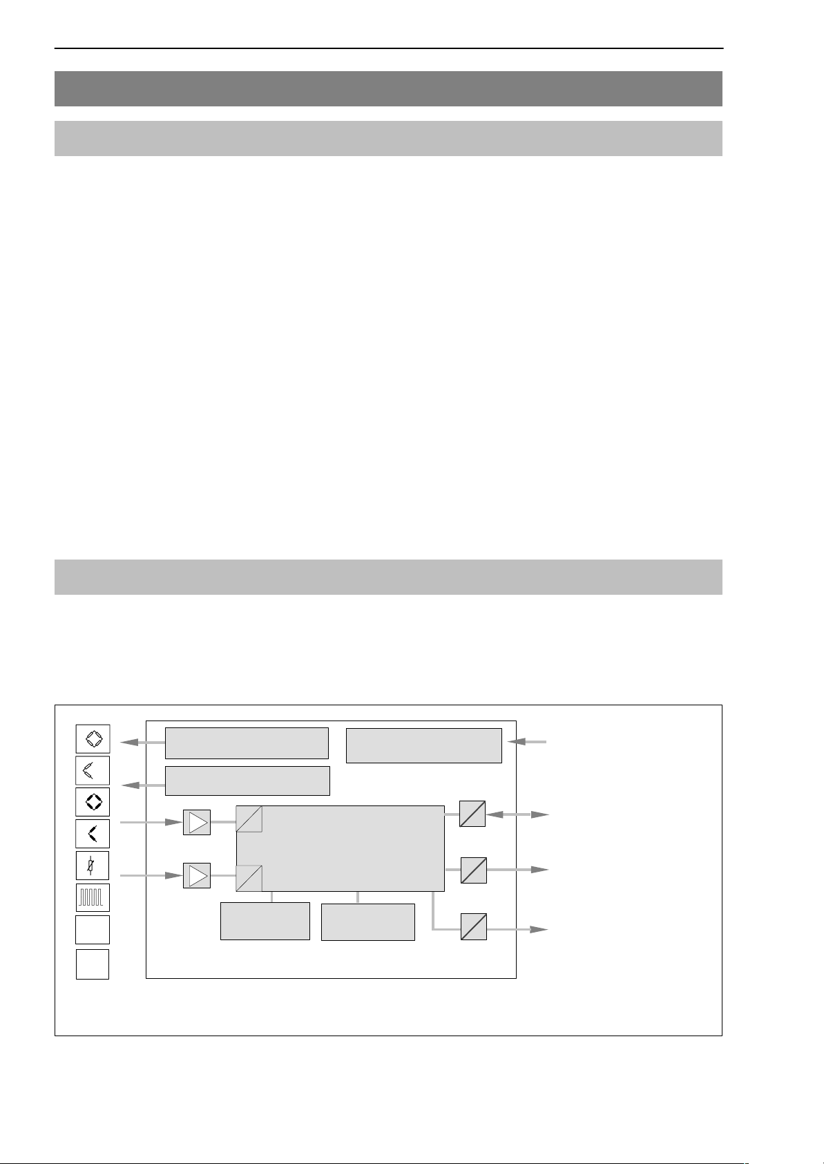
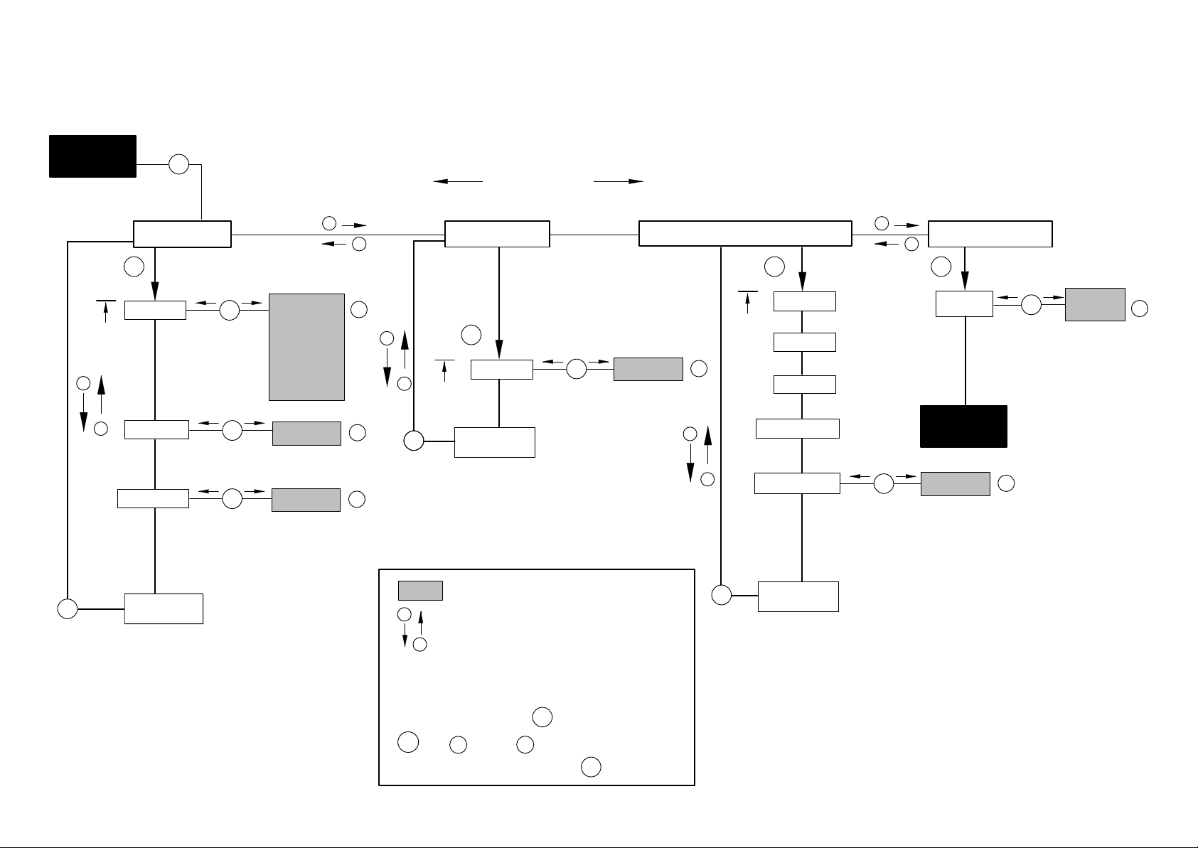
The MP85/MP85DP module from the PME product line is a two−channel
measuring amplifier suitable for connecting the transducers of a great variety
of technologies. In the case of the MP85DP, there is also a Profibus interface
available for CAN-Interface.
Carrier-frequency
excitation voltage 4.8 kHz
Supply for active transducer
5V or 24V
A
D
Intelligent signal conditioning
and powerful algorithms for
A
press-fit monitoring
D
Voltage supply,
electrically isolated
µP
24 V
Control inputs and
control outputs
CANopen
interface
"10V
SSI
Keyboard &
display
MP85 / MP85DP
MMC memory
card
Fig. 1.1: Block diagram of the MP85/MP85DP module
Profibus DP
interface
(for MP85DP)
A0897−3.4 enHBM
Page 9

PME-MP85
The PME Assistant provides a simple user interface under MS-Windows for
parameterizing the modules.
The PME Assistant is the sole means of parameterizing and setting up
the MP85/MP85DP module (described in the Online Help).
To do this you need an LPT → CAN or USB → CAN interface converter, that
has to be ordered separately (1−PMESETUP; 1−PMESETUP-USB).
The software allows you to set all the device parameters apart from the one
for the CAN-BUS interface used for setup.
The software also allows you to set up the other devices of the PME family.
1.3 Valuable information about PME MP85 documentation
MP85 documentation comprises
9
• this Operating Manual,
which describes mainly the configuration of the hardware (transducer,
device and PC with the software).
• the Online Help of the PME Assistant
which describes how to use the software to set up the device
• a separate Operating Manual for the MP85DP with a CAN object index,
CAN interface description and Profibus communication
A0897−3.4 en HBM
Page 10

10
PME-MP85
2 Commissioning
To prepare the MP85 measurement system for a measurement task, the
following conditions must be met or the relevant steps taken:
• You need a PME module MP85 or MP85DP and the PME Assistant,
including software
• The hardware must be configured (transducer, device, PC with the
software) (from Page 16)
• The PME Assistant software must be installed (from Page 18)
• To connect the PME module to a PC, you need a CAN adapter (from Page
17)
− PCAN parallel interface LPT to CAN or
− PCAN USB to CAN or
− PCAN card (PCI or ISA) to CAN
• The PME module must be connected to the CAN adapter
• Once you have started the software, you can set up the PME module with
the PME Assistant (Online Help) (Page 19)
A0897−3.4 enHBM
Page 11
PME-MP85
2.1 Philosophy of operation
2.1.1 Settings on the device
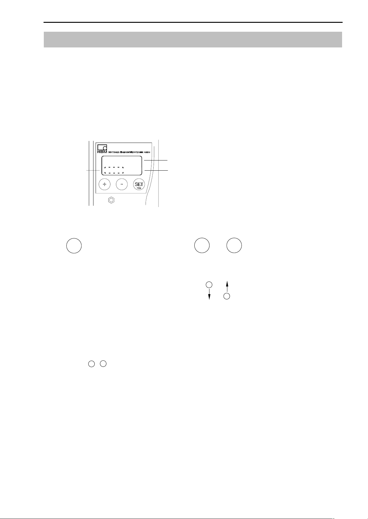
The display of the MP85/85DP shows you the measured value and status
information.
The device is actually set up by means of the “PME Assistant” software
(described in Online Help).
Display in measuring mode:
11
−18.0024
status field
!
kg
x
Function of the keys:
SET
1. Switch from measuring mode to
input mode
2. Choose the first parameter within
the group.
3. Confirm your Input
4. Back to measuring mode (press for
2 secs.)
measured value
unit
+
Select
Parameters/Group
+
−
−
↑
↓
Flashes in the status field if the parameter value can be edited
−
Keys :
+
Keep key pressed − value runs continuously
Short press of the key − advance one value at a time
A0897−3.4 en HBM
Page 12

12
−
During measurement you can press
1. Measured values
• MVx measured value channel x
• MVy measured value channel y
2. Process status, “ProcStat”
• Alarm the last process was finished via the alarm window
• OK the last process was OK
• Not OK the last process was not OK
• Started a process has been started and not yet finished
+
− to view in the display:
PME-MP85
3. Status of the digital inputs and outputs
The MP85 has 5 inputs and 8 outputs.
The MP85DP has 1 input and 4 outputs.
• Input
set, not set
• Output
set, not set
4. Profibus status
BD_SEAR (baud rate search)
WT_PARM (waiting for parameterization)
WT_CONF (waiting for configuration)
DATA_EX (cyclical data traffic)
ERROR (bus error)
A0897−3.4 enHBM
Page 13

PME-MP85
5. MMC-DisplayState (MMCState)
Display Explanation
notinuse No data storage on MMC
with any other display: data storage on MMC
no MMC There is no MMC in the device
Init... The MMC is initialized automatically after insertion
SET ³ STOP MMC ready for storing. Press SET to reset to Stop state.
Then the MMC can be removed.
Storing Data is written to the MMC. Upon completion of data sto-
rage, the state changes to “Ready”; SET ³ STOP is displayed.
Stopped Before removing the MMC from the device,
you must press the SET key to close all files
and write the FAT.
13
The message “MMC Disk Closed” or in case of an error
“MMC DiskClose Err” is displayed for a short time.
Then the MMC changes to the “Stopped” state and can be
removed from the device.
If there is no more free memory available on the MMC, the
status automatically changes to “Stopped”.
The only way to exit this state is to remove the MMC from
the device. Afterwards, there will be an automatic reinitialization.
5. Error types
During measurement, the character ! in the status field (whilst in measuring
mode) indicates a module error.
−
+
The errors are displayed one after the other (obtainable by using
).
• ERROR x (related to screw terminal SENSOR X)
• ERROR y (related to screw terminal SENSOR Y)
SENSOR X
SENSOR Y
Possible error messages are summarized in
Chapter 7 ”Error messages”,
Page 41.
A0897−3.4 en HBM
Page 14
2.1.2 Overview of all groups and parameters
+
SET
+
Up
−
Down
CAN-BUS PROFIBUS ADDITIONAL FUNCTION
Baud rate Address AmplType
Address
OutpR. ms SrNo
MAINGRP
−
Overview of parameters
Groups
MAINGRP
Explanation of parameters:
Load MMC:
Allows you to load a parameter set that has already been
stored on the MMC using the PME Assistant.
PrgVers
HW vers
Load MMC
MAINGRP
We recommend to format the MMC from time to time
for optimizing MMC access times.
MAINGRP with
A0897−3.4 en HBM
SET
back to Group
14
Page 15
2.1.3 Configuring parameters on the device
Measured
value
+
−
2sec
SET
Groups
10kB
20kB
50kB
100kB
+
−
+/-
+
PROFIBUS
SET
ADDITIONAL FUNCTION
AmplTyp
e
PrgVers
CAN bus
SET SET SET
Baud rate
SET
↑
↓
125kB
Address
OutpR. ms
SET
SET
250kB
500kB
1000kB
↑
1−127
↓
↑
↓
000
+/-
+/-
−
SETSET
Address
back
MAINGRP
SET
↑
3 − 123
↓
+/-
SrNo
+
−
HW vers
Load MMC
+
SET
−
Measured
value
↑
↓
MEAS MODE
Save ?
0 − 39
+/-
SET
Yes
↑
↓
No
+/-
SET
back
MAINGRP
A0897−3.4 en HBM
Parameter values
+
Select Parameters
−
↑
↓
Flashes if the parameter value can be edited
SET
Confirm your Input
+/-
=
+ −
or
Back to measuring mode:
Print
SET
2sec
SET
back
MAINGRP
15
Page 16

16
PME-MP85
2.2 Configuring the hardware
2.2.1 Voltage supply / Transducer
• Connect the power supply cable and the transducer to the module
(Chapters 5.3 and 5.4).
CAUTION
Be sure to comply with the safety instructions!
• Activate the power supply.
• The device will run a self-test (approx. 10 secs) and will then, if working
properly, be in measuring mode. During the self-test, the control
outputs stay at 0V.
If ! appears in the display or the status LED shows red, please consult
Chapter 7 ”Error messages”.
• Connecting the bus system
To find out how to connect several devices to a CAN bus, refer to Chapter 5.5.
How to set up the CAN address and the baud rate is described in Chapter
2.1.3.
NOTE
A0897−3.4 enHBM
Page 17

PME-MP85
17
2.2.2 Connecting the CAN adapter (LPT and USB)
To enable PME devices to communicate with the PC, you first have to link the
device to the PC.
1. Connecting LPT to CAN (parallel interface)
• Switch off the PC and attach the LPT to CAN adapter to the parallel
interface port of the PC.
Unfortunately it is not possible to operate a printer from this parallel
interface at the same time. You need a second parallel interface.
• Attach the cable on the adapter between the male connector of the PS2
mouse and the female connector of the PC. This cable is needed to supply
power for the adapter. Alternatively you can attach this power supply cable
between the keyboard connector and the relevant PC socket.
• Attach the CAN connector cable to the MP85 to the adapter.
• Activate the PC.
2. Connecting USB to CAN
First install the PME Assistant.
• Attach the USB to CAN adapter to a free USB interface on your PC.
• The PC will immediately detect the adapter (Plug and Play).
A floppy disk is supplied with the adapter. It includes the driver required for
installation.
A0897−3.4 en HBM
Page 18

18
PME-MP85
2.3 Installing the PME Assistant software
2.3.1 System requirements
To operate the PME Assistant software you need a PC with the following
prerequisites:
− min. processor requirement, Intel Pentium 400 MHz or equivalent
− Windows 95 or higher, Windows NT Version 4.0 or later, Service Pack 3,
Windows 2000
− Internet Explorer 5.0 or higher
− RAM
− 32 MByte for Windows 95/98
− 64 MByte for Windows NT and Windows Millennium
− 128 MByte for Windows 2000 or later
− Graphics card with min. resolution 800 x 600 pixels
− min. 10 MBytes memory available on the hard disk
− Microsoft or 100 % compatible mouse
− configured default printer
− LPT or USB interface
The following fonts must be installed:
− Arial (TT)
− Courier
− MS Sans Serif
− Times New Roman (TT)
− Wingdings
A0897−3.4 enHBM
Page 19

PME-MP85
2.4 Starting the software and setting up
Interface mode
Opens the
Setup window
19
The factory settings
of the interface
CAN bus scan for
connected PME
modules
Fig. 2.1: Startup window
2.4.1 Using the LPT interface
• Start the PME Assistant program and in the startup window, enter the
interface details.
To configure the LPT interface, perform the following steps:
1. In the <Schnittstellentyp> dropdown list box, select the mode PCAN
Dongle Std.
2. Enter the port address of the parallel interface in the <LPT Adresse (hex)>
text box.
NOTE
Under Windows 2000, open System from the Control Panel and click the
Device Manager button on the Hardware tab. Use Connections " Printer
connection to display the available hardware. Double-click on an entry
to open a dialog box to display the requisite information.
3. Select the interrupt of the parallel interface from the <LPT Interrupt>
dropdown list box.
This interrupt must not be used for other devices.
A0897−3.4 en HBM
Page 20

20
NOTE
Under Windows 2000, make sure that an interrupt is used for the
interface: display the properties for the printer connection
(double-click). On the Connection settings tab, each Use interrupt
assigned to the connection must be activated and the interrupt to be
used (interrupt request) must be entered on the Resources tab.
This interrupt must only be used from this interface, double assignment
by a second device, for example, an audio card, is not permissible.
4. In the <CAN−Baudrate> dropdown list box, select the baud rate to be set
for the connected PME modules.
If you do not know the setting, you can use the keyboard of a PME module
to query it (see Page 2.1.1 ).
PME-MP85
The baud rate must be the same for all the PME modules connected to
the CAN bus. The factory setting is 1000 kB.
5. Click the <Scan> button.
In a few seconds, the addresses of the connected PME modules will be
listed in the <CAN−ID> dropdown list box in the Devices area.
6. Select a module and click on <SET>. This opens the Setup window (see
Online Help).
You can now use the PME Assistant software to set up the MP85.
This is described in the Online Help.
NOTE
A0897−3.4 enHBM
Page 21

PME-MP85
2.4.2 Using the USB interface
To configure the USB interface, perform the following steps:
• Start the PME Assistant program and in the startup window, enter the
interface details.
1. In the <Interface type> dropdown list box, select the mode PCAN USB
2. In the <CAN-Baudrate> dropdown list box, select the baud rate to be set
for the connected PME modules.
If you do not know the setting, you can use the keyboard of a PME module
to query it (see Page 2.1.1 ).
NOTE
21
The baud rate must be the same for all the PME modules connected to
the CAN bus. The factory setting is 1000 kB.
5. Click the <Scan> button.
In a few seconds, the addresses of the connected PME modules will be
listed in the <CAN-ID> dropdown list box in the Devices area.
6. Select a module and click on <SET>. This opens the Setup window (see
Online Help).
You can now use the PME Assistant software to set up the MP85.
This is described in the Online Help.
A0897−3.4 en HBM
Page 22

22
PME-MP85
3 Switch settings / Replacing the battery
Modifying the supply voltage for active encoders
Use switch S1 to toggle the supply voltage for active encoders between the
internal 5V supply and the external 24V supply. This is the only changeover
that the housing has to be open for.
NOTE
Switch S1 must be set/modified before fitting the PME.
To set switch S1, proceed as shown in Fig. 3.1.
1
Unscrew the
cover
Switch S1 for the supply
voltage of active encoders
2
S1
5V
(int)
24V
(ext)
Fig. 3.1: Opening the housing, position of switch S1 (schematic diagram)
Terminating resistance
The CAN terminating resistance is activated/deactivated by switch S2 (see
Fig. 3.2).
S2
Toggle switch S2 for the
terminating resistance
ON OFF
Fig. 3.2: Switch for the CAN bus terminating resistance (schematic diagram)
A0897−3.4 enHBM
Page 23

PME-MP85
23
Replacing the battery
The MP85 has a realtime clock which is fed by a type CR2032 lithium battery.
This can be removed from the battery holder and replaced at the point shown
in Fig. 3.3. The battery should be replaced approx. every 5 years.
NOTE
When replacing the battery, you must remove the MP85/MP85DP from
the DIN rail.
1
Battery
for realtime
clock
Unscrew the
cover
2
Fig. 3.3: Opening the housing, position of the battery (schematic diagram)
CAUTION
Check the polarity of the battery
Battery position
−
+
Fig. 3.4: Correct battery position
A0897−3.4 en HBM
Page 24

24
4 MP85/MP85DP mounting/disassembly
(schematic diagrams)
PME-MP85
Fig. 4.1: Mounting on a support rail
Fig. 4.2: Disassembly
CAUTION
The support rail must lie on protective-conductor potential .
A0897−3.4 enHBM
Page 25

PME-MP85
4.1 Linking several modules
Ribbon cable connector
Subsequent devices will be
linked via this connector.
1.
3.
25
Color coding at
Pin 1
2.
58 mm
recommended distance
for the ribbon cable
connectors
Fig. 4.3: Connecting the ribbon cable
Up to four MP85/MP85DP modules can be linked via a ribbon cable. This
cable ensures local connection of the supply voltage, the CAN bus and
synchronization of the carrier frequency between modules.
A0897−3.4 en HBM
Page 26

26
5 Connections
WARNING
Before starting the device, read the safety instructions.
5.1 MP85 functional overview
Local connection of CAN bus, supply voltage and synchronization between
modules
Screw terminal 1:
Voltage supply and CAN bus, synchronization
PME-MP85
LED 1
LED 2
Screw terminal 3:
1 potential-separated control input
(24 V level) incl. input ground,
4 potential-separated control outputs
(24 V level), injection of external supply
for control outputs or incremental or
SSI encoders
Screw terminal 2: (same assignment as
screw terminal 1)
CAN adapter for PC/laptop connection,
parameterization via CAN bus
Two line LC display
Control keys
Multi Media Card (MMC) module
Screw terminal 4:
4 potential-separated control inputs
(24 V level, related to input ground
screw terminal 3)
4 potential-separated control outputs
(24 V level, supply via screw terminal 3)
Screw terminal 5:
Transducer connection channel x
including transducer excitation
Cable shield connection for
transducers
Screw terminal 6:
Transducer connection channel y
including transducer excitation
A0897−3.4 enHBM
Page 27

PME-MP85
5.2 MP85DP functional overview
Local connection of CAN bus, supply voltage and synchronization between
modules
Screw terminal 1:
Voltage supply and CAN bus, synchronization
27
LED 1
LED 2
Screw terminal 3:
1 potential-separated control input
(24 V level) incl. input ground,
4 potential-separated control outputs
(24 V level), injection of external
supply for control outputs or
incremental or SSI encoders
Screw terminal 2: (same assignment as
screw terminal 1)
CAN adapter for PC/laptop connection,
parameterization via CAN bus
Two line LC display
Control keys
Multi Media Card (MMC) module
Connection 4:
9-pin sub-D female connector
for Profibus DP connection
Screw terminal 5:
Transducer connection channel x
including transducer excitation
Cable shield connection for
transducers
Screw terminal 6:
Transducer connection channel y
including transducer excitation
A0897−3.4 en HBM
Page 28

28
PME-MP85
5.3 Supply voltage and control inputs/outputs
Four (MP85) or three (MP85DP) connectable screw terminals are available for
connecting the supply and the control inputs/outputs.
Connecting the voltage
supply:
The MP85/MP85DP module must be connected to an
external supply voltage of 18−30 V (24 V
D The wire ends of the voltage supply must be provided with
D Attach the wire ends to screw terminal 1.
D Insert the screw terminal in the top socket.
D Activate the voltage supply.
Screw terminal 2
(CAN adapter; assignment as
screw terminal 1)
WARNING
end sleeves for strands.
Labeling
nom
CAN
0 V
LH
).
24 V
SYNC
Screw terminal 1
Screw terminal 3
(control inputs/outputs)
Out 1
Out 2
Out 3
Out 4
0V
24V
IN 1
IN
IN = digital input OUT = digital output
CAUTION
1
2
OUT
3
4
0V
24V
1
IN
If there is a power failure at the MP85/MP85DP module, all
the control outputs will be set to 0 V.
Screw terminal 4 (MP85 only)
(voltage supply CAN bus,
synchronization)
(control inputs/outputs)
Out 5
Out 6
Out 7
Out 8
IN 2
IN 3
IN 4
IN 5
5
6
OUT
7
8
2
3
IN
4
5
Fig. 5.1: Screw terminal assignment
The screw terminals are coded so that there will be no confusion when
attaching them to the sockets. Sockets are equipped with coding tabs, screw
terminals 1 and 2 with coding pins.
In the case of screw terminals 3 and 4, the coding lugs are broken off. Screw
terminals 3 and 4, 5 and 6, each have different grid dimensions.
A0897−3.4 enHBM
Page 29

PME-MP85
5.3.1 External supply voltage for control outputs
Example: PLC connection
29
Module MP85/MP85DP
OUT3
OUT1
24 V*
0 V*
Screw terminal 3
max. 0.5 A
PLC
Relay
max. 0.5 A
24 V
0 V*
Fig. 5.2: Connection to a PLC
Control outputs are available at screw terminals 3 and 4 and are electrically
isolated from the internal supply voltage:
• at screw terminal 3: control outputs 1 − 4
• at screw terminal 4: control outputs 5 − 8 (MP85 only)
)
*
Control outputs must be supplied with an external voltage (ground and
24V) via screw terminal 3.
5.3.2 Reference potential for control inputs
Control inputs are available at screw terminals 3 and 4 and are electrically
isolated from the internal supply voltage and from the control outputs.
• at screw terminal 3: control input 1
• at screw terminal 4: control inputs 2 − 5 (MP85 only)
For control inputs, it is necessary to connect an external reference potential
(
IN ) to which the control input signals relate.
A0897−3.4 en HBM
Page 30

30
PME-MP85
5.4 Transducer
2 transducers can be independently connected at screw terminals 5 and 6.
5.4.1 Transducers with carrier frequency excitation
In “carrier frequency amplifier” mode, the following transducer types can be
connected:
Screw terminals 5 and 6
for transducer connection
SENSOR X
18
SENSOR Y
18
S.G. and inductive full bridges,
piezoresistive transducers
WH
Measurement
signal (+)
BK
Excitation voltage (−)
RD
Measurement
signal (−)
BU
Excitation voltage (+)
GN
Sensor circuit (+)
GY
Sensor circuit (−)
YE
Cable shield
MP85
1
2
6
4
5
3
Hous.
MP85DP
S.G. and inductive half bridges
WH
Measurement
signal (+)
BK
Excitation
voltage (−)
BU
Excitation
voltage (+)
GN
Sensor circuit (+)
GY
Sensor circuit (−)
YE
Cable shield
1
2
4
5
3
Hous.
Potentiometric transducer *
Measurement
signal (+)
Excitation
voltage (−)
2
1
3
Excitation
voltage (+)
Cable shield
Sensor circuit (+)
Sensor circuit (−)
)
1
2
4
Hous.
5
3
LVDT transducer
Measurement
signal (+)
Excitation
voltage (−)
Excitation
voltage (+)
Measurement
signal (−)
Cable shield
Sensor circuit (+)
Sensor circuit (−)
1
2
4
6
Hous.
5
3
Cable core colors:
WH= white; BK= black; BU= blue; RD= red; YE= yellow; GN= green; GY= gray
Fig. 5.3: Connection of different transducers in “carrier frequency amplifier” mode
*)Function halfbridge
A0897−3.4 enHBM
Page 31

PME-MP85
31
When connecting a transducer in four-wire technology, the sensor circuits
must be linked to the relevant bridge excitation circuit (pin 3 with pin 2 and pin
1)
5 with pin 4)
.
Four-wire connection:
Full bridge
WH
BK
RD
BU
YE
Hous
1
2
6
4
5
3
.
Four-wire connection:
Half bridge
WH
BK
BU
GN
GY
YE
Hous
1
2
6
4
5
3
.
Feedback bridges for four-wire technology
Cable core colors: WH= white; BK= black; BU= blue; RD= red; YE= yellow; GN= green; GY= gray
Fig. 5.4: Transducer connection in four-wire technology
NOTE
To connect the transducers, use standard cable from HBM or another
shielded, low-capacitance measurement cable. Connect the shield of
each transducer cable via the shortest possible lead (t5 cm) and a
blade connector (4.8 mm; “Faston”) to the right of screw terminal 6. This
ensures EMC protection.
1)
For cable lengths >50 m, instead of feedback bridges, a resistance with half the value of the bridge
resistance (RB/2) must be activated at the transducer. If the transducers are calibrated in a six-wire circuit,
the resistances must be activated directly into the sensor circuit.
A0897−3.4 en HBM
Page 32

32
Synchronization:
Synchronization is advisable for carrier-frequency fed transducers if
D the transducer cables of several devices are installed side by side
D the measuring points are close together and unshielded
Synchronisation prevents carrier frequency differences leading to disturbing
superpositions.
PME-MP85
When synchronizing several modules, one device has to be declared the
master. The remaining devices must be set to slave (use Setup).
Synchronization between modules should always − even if you are working
without a CAN bus − be effected with the ribbon cable.
NOTE
A0897−3.4 enHBM
Page 33

PME-MP85
33
5.4.2 Active encoders
In “incremental encoder, SSI transducer or direct voltage encoder” mode, the
following transducer types can be connected:
MP85
MP85DP
Pulse counter, incremental transducer (symmetric signals)
Ground
Ground
o
o
f1, 0
f1, 0
o
o
f2, 90
f2, 90
Transducers with SSI interface (symmetric signals)
Measurement signal F1 (+), 0°
Measurement signal F1 (−), 0°
Cable shield
Measurement signal F2 (+), 90°
Measurement signal F2 (−), 90°
Zero index, Ix (+)
Zero index, Ix (−)
Supply voltage +5 V/+24 V
Ground
Clock, Cl (+)
7
6
1
Hous.
5
3
4
2
8
7
6
Clock, Cl (−)
Cable shield
Data, D (+)
Data, D (+)
Supply voltage +5 V/+24 V
DC voltage sources ("10V)
Measurement signal (+)
U
Measurement signal (−)
Cable shield
Fig. 5.5: Connecting active encoders
1
Hous.
5
3
8
5
3
Hous.
A0897−3.4 en HBM
Page 34

34
PME-MP85
A supply voltage is available at screw terminals 5 and 6, pins 7 and 8 for
feeding incremental transducers and transducers with an SSI interface.
Switch S1 is used to toggle between an internal and an external supply. The
device has to be opened to do this. (see Chapter 3).
• Transducer supplied from the MP85/MP85DP:
Transducer supply voltage 5V "10 %, 150 mA max. (for both channels
together). The supply is then not electrically isolated from the
measurement system.
• Transducer supplied from an external power pack:
At screw terminal 3, pins 5 and 6, a voltage between 10 − 30 V
24 V
) including ground is applied. A current of max. 300 mA (for both
DC
(nominal
DC
channels together) can then be drawn at transducer terminals 5 and 6.
This external supply voltage is electrically separated from the signal ground
and at the same time feeds the digital control outputs.
Screw terminal 3
GND_int 5 V_int
GND_ext
24 V_ext
5
6
S1
78
Screw terminal 5
GND +5 V / 24 V
Screw terminal 6
78
Fig. 5.6: Supplying active encoders (schematic diagram)
A0897−3.4 enHBM
Page 35

PME-MP85
35
5.5 CAN interface
The CAN bus is connected via screw terminal 1. A maximum of 32 CAN
nodes can be connected in one bus segment (under CANopen specification).
The CAN bus needs a terminating resistance of 120 Ω in the first and last bus
nodes. The bus line must have no more than two terminating resistances. A
terminating resistance is integrated in the MP85DP module and is activated
by toggle switch S2.
Low High
1st device
Fig. 5.7: Connecting the CAN interface
CAN low
CAN connection
as per Fig. 5.7
First device in
the bus line
Switch in the
terminating resistance
here (toggle switch)
Do not switch in the
terminating resistance
CAN high
Last device in
the bus line
Switch in the
terminating resistance
here (toggle switch)
Fig. 5.8: CAN bus mode with several modules (max. 32 according to the standard)
NOTE
If the first or last device in the bus line is not a PME module, a 120 W
resistance must be switched in to each of these external devices.
A0897−3.4 en HBM
Page 36

36
PME-MP85
5.6 Profibus interface (MP85DP only)
On the front panel of the MP30DP is a 9-pin D-sub connection socket for the
Profibus connection.
GND
9
RS485-A
5
RS485-RTS
RS485-B
Vcc (5V)
6
1
Profibus
connection socket
Fig. 5.9: Profibus connection in accordance with standard
Installation:
• Connect the MP85DP module to the 24 V supply voltage and set the
required Profibus address via the keyboard or the Setup program.
• Connect the Profibus cable to the MP85DP module. Ensure that a
terminating resistance is connected to the first and last Profibus unit (the
housing of the Profibus connector usually contains a sliding switch for this
purpose).
Example:
Profibus
connector
First device in
the bus line
sliding switch of Profibus connector
to ”Resistance ON” . . . .
Fig. 5.10: Profibus operation
PLC
Profibus
connector
Last device in
the bus line
sliding switch of Profibus connector
to ”Resistance ON”
A0897−3.4 enHBM
Page 37

PME-MP85
37
6 Communication with the control system
All the diagrams relate to a positive logic.
6.1 Timing of the test operations
a.) Storing curves and results without data loss
The below diagrams apply, if you choose the “without data loss” storage method and want to save curves and/or results on the MMC or externally via
CAN. The READY signal is not reset to 1 until the device is ready to save data
for the next process.
NOTE
Before starting a new measurement, the READY bit must have been reset to 1.
Start/Stop Input
Ready
Running
Result valid
External stop
The READY signal is
not reset to 1 until
there has been an
external stop.
External stop or end condition
occurred
Process in order
State undefined
Once the evaluation time
has expired, you can
Initialisization typ. 25 ms
Data acquisition running
Time until stop
Offline evaluation
Data storage
A0897−3.4 en HBM
read off result 0 or 1 at
the output.
Only if “Result valid” = 1,
the process result (Process in order) is valid.
Page 38

38
PME-MP85
b.) Process optimized storage of curves and results
The below diagrams apply, if you choose the “Process optimized storage” storage method and want to save curves and/or results on the MMC or externally
via CAN. In contrast to the “Storing without data loss” method, the READY signal can be reset to 1 even if the device is not yet ready to save new data.
Consequently the results and curve files might not be transmittes if you start a
new measurement immediately. This method should only be chosen if extremely fast processes must be monitored and the results and curves are merely
used for random sample checks.
NOTE
Before starting a new measurement, the READY bit must have been reset to 1.
Start/Stop Input
Ready
Running
Result valid
External stop
The READY signal is
not reset to 1 until
there has been an
external stop.
External stop or end condition occurred
Process in order
Initialisization typ. 25 ms
Data acquisition running
State undefined
Time until stop
Offline evaluation
Once the evaluation time
has expired, you can
read off result 0 or 1 at
the output.
Only if “Result valid” = 1,
the process result (Process in order) is valid.
Data storage
A0897−3.4 enHBM
Page 39

PME-MP85
6.2 Transducer test
Transducer test timing diagram
39
min. 5 ms
Input
Transducer test
Output transducer test result
6.3 Zero balance
Zero balance timing diagram
min. 5 ms
Inputs
Zeroing
1
0
typically 10 ms
1
0
Input
START
Settling time e.g. for
100 Hz filter: 20 ms
A0897−3.4 en HBM
Page 40

40
6.4 Parameter set switching
PME-MP85
Inputs
Switchover occurs when the level changes
Load parameter set
bit 0 − bit 4
Output Busy
typically 500 ms
Bit 4 Bit 3 Bit 2 Bit 1 Bit 0 Active parameter set
0 0 0 0 0 Factory settings
0 0 0 0 1 1
0 0 0 1 0 2
0 0 0 1 1 3
0 0 1 0 0 4
0 0 1 0 1 5
0 0 1 1 0 6
0 0 1 1 1 7
0 1 0 0 0 8
0 1 0 0 1 9
0 1 0 1 0 10
0 1 0 1 1 11
0 1 1 0 0 12
0 1 1 0 1 13
0 1 1 1 0 14
0 1 1 1 1 15
1 0 0 0 0 16
1 0 0 0 1 17
1 0 0 1 0 18
1 0 0 1 1 19
1 0 1 0 0 20
1 0 1 0 1 21
1 0 1 1 0 22
1 0 1 1 1 23
1 1 0 0 0 24
1 1 0 0 1 25
1 1 0 1 0 26
1 1 0 1 1 27
1 1 1 0 0 28
1 1 1 0 1 29
1 1 1 1 0 30
1 1 1 1 1 31
A0897−3.4 enHBM
Page 41

PME-MP85
7 Error messages/operating status (LED)
Depending on the display mode, various error messages can appear in the
display instead of the measured value.
Error message Cause Remedy
TransdErr. Input signal overflow
Transducer not connected
Transducer wrongly connected
Amplifier not adapted to transducer
type
No sensor circuits connected
Connect transducer
See pin assignment
Connect sensor circuits
41
ADC ovfl. Input signal of the A/D converter too
high
Grs ovfl. Gross value overflow Reduce display by one decimal
Scal.Err Input characteristic too steep Modify input characteristic
Flash error An error occurred when reading out
the Flash EOROM.
An error occurred at the CAN bus Check whether there are termi-
CAN bus error
Initial calibr. error No valid initial calibration values Start again, send PME to the
CAN Tx No PDO request on bus Check CAN bus configuration
Adjust hardware measuring
range
place
This can be a one-off read error,
please repeat the operation. If
the error occurs again, please
contact HBM Service.
nating resistances or whether a
channel is faulty. Then switch the
devices back on. If this does not
help, connect one device at a
time to the CAN bus to ascertain
which device is faulty.
manufacturer (HBM)
A0897−3.4 en HBM
Page 42

42
PME-MP85
Operating status MP85 / MP85DP:
The LEDs show the operating status (ready to take measurements, overflow
etc.) of the device.
With the MP85DP, however, the Profibus status is displayed instead of the
CAN status (as is the case with the MP85).
LED 1
LED 2
Operating status:
LED1 (OK / NOK)
Operating status LED Red LED Yell LED Green LED Flashes
Initialization during start-up x
Alarm x x
Process starts x x
OK x
Not OK x
LED2 (Status)
MP85 LED Red LED Yell LED Green LED Flashes
Initialization during start-up x
EE_InCalErr x
CANOFF x
No synchronization signal x
Scale error x
MMC error x
Overload x x
LCD Err x x
CAN communitation x x
PreOperational x
Operational x
MP85DP LED Red LED Yell LED Green LED Flashes
Status: Error x
Status: BD_SEAR, WT_PARM, WT_CONF x
Status: DATA_EX x
A0897−3.4 enHBM
Page 43

PME-MP85
8 Specifications
Type MP85 / MP85DP
Accuracy class 0.1
43
Supply voltage V
DC
24; Potential separation from measuring
system (typically 500 V
Permitted supply voltage range V 18...30
Power consumption
MP85, typically
MP85DP, typically
MP85 / MP85DP, max.
Backing battery for realtime clock
W
W
W
10
Years 5
7
9
(CR2032), typical lifetime
Operating modes, independently adjustable for both channels
Carrier-frequency amplifier
Carrier frequency kHz 4.8 "1 %
Excitation voltage V
rms
2.5 "5 %
Attachable process quantity transducer
S.G., half and full bridges
Inductive half and full bridges, LVDTs
Potentiometric transducer
Ω
mH
Ω
170 − 2000
4 − 160
170 − 2000
Input sensitivity Measuring range (mV/V)
4 100 1000
mV/V 0.2 − 4 3.5 − 100 50 − 1000
Transducer cable length, max. m 500
DC
.)
Scale range, max. Digits 999999, at 10 % of input measuring
range
Scale range, min. Digits 100, at 100 % of input measuring range
Maximum permitted common-mode
voltage
V "5,5
Common-mode rejection
0 − 60
0 − 1000
0 − 4800
dB
dB
dB
u120
u96
u50
Linearity deviation % t0.03
Noise voltage typically Measuring range (mV/V)
4 100 1000
0 - 1 Hz
0 − 10 Hz
0 − 100 Hz
0 − 1000 Hz
µV/V
µV/V
µV/V
µV/V
pp
pp
pp
pp
0.1
0.25
1
2
2.5
6
25
50
25
60
250
500
Sampling rate, max. 1/s 2400
A0897−3.4 en HBM
Page 44

44
Measurement frequency range
adjustable
Low pass 4th order with Bessel
characteristic
Nomin
al
(rated)
value
fc (Hz)
1000 980 1400 0.550 0.260 4
,
0.05 0.049 0.081 3750 4280 0
−1dB
off 790 1200 0.450 0.290 3
500 440 690 0.860 0.510 1.5
200 190 320 1.6 1.11 1.5
100 100 160 2.9 2.13 1.3
50 51 83 4.6 4.24 1
20 25 41 8.2 8.36 1
10 13 21 15.5 16.8 0
5 6.1 10.3 30.2 33.4 0
2 3.1 5.2 60 67 0
1 1.6 2.6 119 137 0
0.5 0.79 1.30 240 272 0
0.2 0.19 0.32 950 1070 0
0.1 0.09 0.16 2500 2170 0
−3dB
(Hz)
(Hz)
Phase
delay
(ms)
PME-MP85
Rise
time
(ms)
Over-
shoot
Shunt calibration mV/V 1"3%
Effect of operating voltage
on zero point
on sensitivity
Effect of 10 K change in ambient
% f.s.
% f.s.
Measuring range (mV/V)
t0.01
t0.01
temperature
4 100 1000
on zero point full bridge
on zero point half bridge
on sensitivity
Long-term drift over 48 h(meas. range
µV/V
µV/V
%
1
10
0.05
20
40
0.05
µV/V 2
200
200
0.05
4 mV/V; 0.5 h after powering up)
DC-voltage transducer
Attachable process quantity transducer DC-voltage transducer, voltage sources
Nominal (rated) measuring range V "10
(%)
Input signal range V "10.5
Scale range, max. Digits 999999, at 10 % of input measuring range
Scale range, min. Digits 100, at 100 % of input measuring range
Internal resistance of the signal source kΩ v1
Maximum permitted common-mode
V 2
voltage
Measurement frequency range,
Hz 0.05 − 1000
adjustable (-1 dB)
Filter characteristics Bessel, 4th order
Linearity deviation % t0.03
Sampling rate max. 1/s 2400
A0897−3.4 enHBM
Page 45

PME-MP85
Incremental encoder
Attachable process quantity transducer Incremental encoder (up/down counter
with zero index signal)
Voltage supply 5 V, max. 150 mA or 24 V
max. 300 mA
Dual-channel mode Time division multiplex method
Inputs (F1 ("), F2 ("), Ix (")) Differential inputs (RS422)
Input level
LOW level
HIGH level
Each line to measurement earth, max.
Hysteresis, typically V 0.07
Maximum permitted common-mode
voltage
Input impedance, typically kΩ 12
Detection of direction of rotation Via "90o phase-shifted signal F2
Input range pulse counting Imp 0 − 999999
V
V
V
V −7 ... +12
t0.8
u2
"14
45
Maximum pulse rate Imp/s 1 000 000
Gap between two consecutive edges
F1("), F2(")
Scale range, max. Digits 20 for 1 pulse
Scale range, min. Digits 1 for 10,000 pulses
Measurement frequency range,
adjustable (-1 dB)
Sampling rate max. 1/s 2400
SSI transducer
Attachable process quantity transducer Disp. and angle transducer with SSI inter.
Power supply 5 V, max. 150 mA; 24 V, max. 300 mA
Dual-channel mode Time division multiplex method
Data inputs D (") Differential input (RS422)
Input level, data input D (")
LOW level
HIGH level
Each line to measurement earth, max.
Hysteresis V 0.07
Maximum permitted common-mode
voltage
Clock output Cl (")
Differential output voltage Cl("), without
load, max.
Differential output voltage Cl("), RL= 50
Ohm, min.
Common-mode output voltage on Cl
("), max.
ns u400
Hz 0.05 − 1000
V
V
V
V −7 ... +12
Differential output (RS422)
V
V
V 3
t0,8
u2
"14
5.8
2
Short-circuit current, clock outputs
Cl ("), typically
A0897−3.4 en HBM
mA 100
Page 46

46
Resolution, single turn Bits 12, 13
Resolution, multi turn Bits 24, 25
Scale range, max. Digits 20 for 1 pulse
Scale range, min. Digits 1 for 10,000 pulses
PME-MP85
Measurement frequency range,
Hz 0.05 − 1000
adjustable (-1 dB)
Sampling rate, max. 1/s 1200
Baud rates kBaud 100, 200, 500, 1000
Coding Gray Code
General specifications
Limit switches
Number 4 per channel
Reference level Gross
Hysteresis % 1 ... 100
Adjustment accuracy Digit 1
Response time, typically (fc=1000 Hz) ms t2
Control outputs
Number 4 (MP85DP) / 8 (MP85)
Nominal voltage, external power supply V
DC
24
Permitted supply voltage range V 10 − 30
Maximum output current per output A 0.5
Short-circuit current, typically
. = 24 V, RLt 0.1 Ohm)
(U
ext
A 0.8
Short-circuit period Unlimited
Isolation voltage, typically V
DC
500
Control inputs
Number 1 (MP85DP) / 5 (MP85)
Input voltage range LOW V 0 − 5
Input voltage range HIGH V 10 − 30
Input current, typically (HIGH level = 24V) mA 12
Isolation voltage, typically V
DC
500
CAN interface
Sampling rate, max. 1/s 1200
Protocol CAN 2.0B, CANopen compatible
Hardware bus link to ISO 11898
Baud rates
Maximum cable lengths
Kbit/sm1000 500 250 125 100 50 20 10
25 100 250 500 600 1000 10001000
Terminating resistance Connectable by switch
Connection Terminals
Parameter memory (Flash) 31 plus factory settings
A0897−3.4 enHBM
Page 47

PME-MP85
Multimedia card (memory card on Flash base)
47
Usable types M-
bytes
Data transmission rate, typically K-byte
/s
File system DOS
Display
Type Two line, 8 character alphanumeric, LCD
Keyboard Touch-sensitive keypad with three keys
Temperature range
Nominal temperature range
Operating temperature range
Storage temperature range
Degree of protection IP20
Dimensions mm 55 x 146 x 156
Weight, approx. g 800
Profibus DP interface (MP85DP only)
o
C 0 − 50
o
C −20 ... +50
o
C −20 ... +70
8, 16, 32, 64
8
Protocol Profibus DP slave, as per DIN 19245−3
Baud rate, max. MBaud 12
Node address 3 − 123, can be set via keyboard
Profibus ID number Hex 699
Configuration data byte 5
Parameter data, max. byte 6 (+7DP standard)
Parameter assignment (asynchronous) to DPV1 standard
Input data, max. byte 142
Output data, max. byte 40
Inputs update rate ms 1 (for 4 measured values)
Outputs update rate ms t10, on zeroing, limit values
Diagnosis data byte 48
Profibus connection 9-pin sub-D (DIN19245-3),
potential-separated from power supply
and signal ground
A0897−3.4 en HBM
Page 48

48
Specifications for analysis unit
PME-MP85
Max. number of data triples
4000 (auto. data reduction)
(channel x); (channel y); (time)
Sampling rate, max. Hz 2400
Analysis
Max. number of analysis windows 9
Type of window Oblique or straight
Analysis methods per window Plot analysis
Mean value of x or y analysis in window
x coordinates for tolerance windows absolute or relative to the start position, or
relative to the end position
Y coordinates for tolerance windows absolute or
relative to F
of tolerance window 2
min
or
relative to F
of tolerance window 2
max
Stop conditions External stop signal
Target value y + decay time
Target value x + decay time
Standstill recognition
Number of independent parameter sets 31
Switching parameter sets, max. ms 500
Duration of offline evaluation straight
ms 15 + 0.15/data pair in window
window
Duration of offline evaluation oblique
ms 15 + 0.3/data pair in window
window
Statistics (for each parameter set, separately)
Maximum number of fitting processes 4 x 10
Number of histogram classes for 2
, x
values (x
max
min
, y
max
, y
min
)
9 per tolerance window
9
A0897−3.4 enHBM
Page 49

PME-MP85
9 Declaration of conformity
49
A0897−3.4 en HBM
Page 50

50
PME-MP85
A0897−3.4 enHBM
Page 51

PME-MP85
10 Keyword index
51
A
active encoders, 22 , 33
active parameter set, 40
C
CAN bus, 15 , 26 , 27 , 35
connecting, 26 , 27
CAN interface, 35
CANopen, 35
CANopen interface, connecting, 35
coding pin, 28
coding tab, 28
commissioning, 10
configuring parameters, 15
connecting
bus system, 16
CAN adapter, 17
CAN adapters, 9
CAN interface, 35
LPT to CAN, 17
supply voltage, 28
transducers, 30 , 33
USB to CAN, 17
D
DC voltage source, 33
declaration of conformity, 49
digital input, 28
digital inputs, 12
digital output, 28
disassembly, 24
display mode, 13
dongle, 19
E
error message, 41
F
feedback bridges, 31
four−wire technology, 31
I
interface, connecting, 35
interface converter, 9
connecting the bus system, 16
connecting transducers, 30
active encoders, 33
S.G. full and half bridges, inductive full
and half bridges, potentiometric, piezoelectric, LVDT, 30 , 33
transducers with CF excitation, 30
connection, pulse counter, incremental
transducer, symmetric, 33
control inputs, 26 , 27
control inputs and outputs, 26 , 27
control outputs, 26 , 27
A0897−3.4 en
L
LED, 42
LPT interface, 19
M
measured value channel x, measured va-
lue channel y, 12
MMC load, 14
MMC−State, 13
mounting, 24
multimedia card, 8
HBM
Page 52

52
PME-MP85
P
parameters, 14
configuring, 15
PLC connection, 29
PME Assistant, 18
power failure, 28
process status, 12
Profibus interface, 36
Profibus status, 12
R
replacing the battery, 22 , 23
ribbon cable, 32
S
screw terminal assignment, 28
self−test, 16
supply voltage, 28
synchronization, 26 , 27 , 32
T
terminating resistance, 22 , 35
Test timing, 39
U
USB interface, 21
V
voltage supply, 26 , 27 , 28
screw terminal, 26 , 27
voltage supply, CAN bus, synchroniza-
tion, control inputs, control outputs, 26
, 27
Z
Zero balance, 39
HBM
A0897−3.4 en
Page 53

PME-MP85
53
A0897−3.4 en
HBM
Page 54

54
PME-MP85
HBM
A0897−3.4 en
Page 55

Page 56

pp
A0897−3.4 en
Modifications reserved.
All details describe our products in general form only.They are
not to be understood as express warranty and do not constitute
any liability whatsoever.
Hottinger Baldwin Messtechnik GmbH
Postfach 10 01 51, D-64201 Darmstadt
Im Tiefen See 45, D-64293 Darmstadt
Tel.: +49/61 51/ 8 03-0; Fax: +49/61 51/ 8039100
E−mail: su
ort@hbm.com www.hbm.com
 Loading...