

Page 1
Operating Manual
Twin-channelAmplifiers
Modules
MP85A, MP85ADP
FASTpress
MP85A-S, MP85ADP-S
EASYswitch
A2392−5.0 en
Page 2

Page 3

MP85A process controller
3
Contents Page
Contents
Safety information 5. . . . . . . . . . . . . . . . . . . . . . . . . . . . . . . . . . . . . . . . . . . . . . .
1 Introduction 10. . . . . . . . . . . . . . . . . . . . . . . . . . . . . . . . . . . . . . . . . . . . . . . . .
1.1 Scope of supply and accessories 10. . . . . . . . . . . . . . . . . . . . . . . . . .
1.2 General information 11. . . . . . . . . . . . . . . . . . . . . . . . . . . . . . . . . . . . . .
1.3 About this documentation 12. . . . . . . . . . . . . . . . . . . . . . . . . . . . . . . . .
2 MP85A(DP)(-S) installation/removal (basic diagrams) 13. . . . . . . . . . .
2.1 Mechanical installation 13. . . . . . . . . . . . . . . . . . . . . . . . . . . . . . . . . . .
2.2 Connecting several devices 14. . . . . . . . . . . . . . . . . . . . . . . . . . . . . . .
3 Electrical connection 15. . . . . . . . . . . . . . . . . . . . . . . . . . . . . . . . . . . . . . . . .
3.1 Overview of MP85A/MP85A-S functions 15. . . . . . . . . . . . . . . . . . . .
3.2 Overview of MP85ADP/MP85ADP-S functions 16. . . . . . . . . . . . . . .
3.3 Supply voltage and control inputs/outputs 17. . . . . . . . . . . . . . . . . . .
3.3.1 External supply voltage for control outputs 18. . . . . . . . . . . . .
3.3.2 Reference potential for control inputs / switch check inputs . .
18
3.4 Transducer 19. . . . . . . . . . . . . . . . . . . . . . . . . . . . . . . . . . . . . . . . . . . . .
3.4.1 Synchronization of carrier frequencies 19. . . . . . . . . . . . . . . .
3.4.2 SGs, displacement transducers, potentiometric and LVDT
sensors 20. . . . . . . . . . . . . . . . . . . . . . . . . . . . . . . . . . . . . . . . . . .
3.4.3 Incremental, SSI and DC sensors 22. . . . . . . . . . . . . . . . . . . .
3.4.4 Piezoelectric measurement chains 24. . . . . . . . . . . . . . . . . . .
3.5 TEDS-transducers (electronic data sheet) 27. . . . . . . . . . . . . . . . . . .
3.5.1 TEDS connection 27. . . . . . . . . . . . . . . . . . . . . . . . . . . . . . . . . .
3.5.2 Parameterization with TEDS 27. . . . . . . . . . . . . . . . . . . . . . . . .
3.6 Interfaces 28. . . . . . . . . . . . . . . . . . . . . . . . . . . . . . . . . . . . . . . . . . . . . . .
3.6.1 Ethernet interface 29. . . . . . . . . . . . . . . . . . . . . . . . . . . . . . . . . .
3.6.2 CAN interface 30. . . . . . . . . . . . . . . . . . . . . . . . . . . . . . . . . . . . .
3.6.3 PROFIBUS interface (MP85ADP/MP85ADP-S only) 31. . . .
4 Switch settings / Replacing the battery 33. . . . . . . . . . . . . . . . . . . . . . . .
5 Starting up/Setting up mode 36. . . . . . . . . . . . . . . . . . . . . . . . . . . . . . . . . .
5.1 Operation 37. . . . . . . . . . . . . . . . . . . . . . . . . . . . . . . . . . . . . . . . . . . . . . .
5.1.1 Device settings, measured values, process status,
PROFIBUS, memory cards, error types, firmware update,
device backup 37. . . . . . . . . . . . . . . . . . . . . . . . . . . . . . . . . . . . .
5.1.2 Overview of all groups and parameters 42. . . . . . . . . . . . . . . .
A2392−5.0 en HBM
Page 4

4
MP85A process controller
5.1.3 Setting parameters on the device 44. . . . . . . . . . . . . . . . . . . . .
5.2 Hardware setup 45. . . . . . . . . . . . . . . . . . . . . . . . . . . . . . . . . . . . . . . . .
5.2.1 Voltage supply / transducers 45. . . . . . . . . . . . . . . . . . . . . . . . .
5.2.2 Establishing the Ethernet connection 46. . . . . . . . . . . . . . . . .
5.2.3 Connecting the CAN adapter (USB) 47. . . . . . . . . . . . . . . . . .
5.3 Installing the PME Assistant software 47. . . . . . . . . . . . . . . . . . . . . . .
5.4 PME Assistant operation 48. . . . . . . . . . . . . . . . . . . . . . . . . . . . . . . . . .
5.4.1 Using the Ethernet interface 48. . . . . . . . . . . . . . . . . . . . . . . . .
5.4.2 Using the USB interface 49. . . . . . . . . . . . . . . . . . . . . . . . . . . .
5.5 Automatic version recognition 50. . . . . . . . . . . . . . . . . . . . . . . . . . . . .
5.6 Firmware update 50. . . . . . . . . . . . . . . . . . . . . . . . . . . . . . . . . . . . . . . . .
5.7 Offline operation 51. . . . . . . . . . . . . . . . . . . . . . . . . . . . . . . . . . . . . . . . .
6 Methods of measurement 52. . . . . . . . . . . . . . . . . . . . . . . . . . . . . . . . . . . . .
6.1 Data reduction 52. . . . . . . . . . . . . . . . . . . . . . . . . . . . . . . . . . . . . . . . . . .
6.2 Classification 53. . . . . . . . . . . . . . . . . . . . . . . . . . . . . . . . . . . . . . . . . . . .
6.3 Monitoring limit values in real time 53. . . . . . . . . . . . . . . . . . . . . . . . .
6.4 Masking out external tolerances 54. . . . . . . . . . . . . . . . . . . . . . . . . . .
6.5 Evaluation criteria 54. . . . . . . . . . . . . . . . . . . . . . . . . . . . . . . . . . . . . . . .
6.6 Measurement programs (parameter sets) 58. . . . . . . . . . . . . . . . . . .
7 Switch checker with MP85A(DP)-S EASYswitch 60. . . . . . . . . . . . . . . .
7.1 Switch check 60. . . . . . . . . . . . . . . . . . . . . . . . . . . . . . . . . . . . . . . . . . . .
7.2 Haptic check 62. . . . . . . . . . . . . . . . . . . . . . . . . . . . . . . . . . . . . . . . . . . .
8 Communication with a control system 63. . . . . . . . . . . . . . . . . . . . . . . . .
8.1 MP85A process controller in machine control 63. . . . . . . . . . . . . . . .
8.2 Test process sequence over time 65. . . . . . . . . . . . . . . . . . . . . . . . . .
8.3 Transducer test 67. . . . . . . . . . . . . . . . . . . . . . . . . . . . . . . . . . . . . . . . . .
8.4 Zero balance 68. . . . . . . . . . . . . . . . . . . . . . . . . . . . . . . . . . . . . . . . . . . .
8.5 Simulation of digital outputs 68. . . . . . . . . . . . . . . . . . . . . . . . . . . . . . .
8.6 Parameter sets (measurement programs) 69. . . . . . . . . . . . . . . . . . .
8.7 Evaluation/storage process times 71. . . . . . . . . . . . . . . . . . . . . . . . . .
8.8 Process data storage/production data management 73. . . . . . . . . .
9 Display-and control options 76. . . . . . . . . . . . . . . . . . . . . . . . . . . . . . . . . . .
9.1 DT85 control and display terminal 76. . . . . . . . . . . . . . . . . . . . . . . . . .
9.2 FASTpress Suite software 77. . . . . . . . . . . . . . . . . . . . . . . . . . . . . . . .
10 Error messages/operating state (LED display) 79. . . . . . . . . . . . . . . . . .
11 Technical support 83. . . . . . . . . . . . . . . . . . . . . . . . . . . . . . . . . . . . . . . . . . . .
A2392−5.0 enHBM
Page 5

MP85A process controller
5
Safety information
This operating manual applies to the devices
• MP85A
• MP85ADP
• MP85A-S
• MP85ADP-S
The designation MP85A process controller will be used for all devices in this
manual. If text/data refers only to specific devices, this will be clearly indicated
in the text and one of the above designations used.
• Use shielded, low-capacitance HBM cables only.
Intended use
The MP85A process controller is to be used exclusively for measurement
tasks and directly related control tasks. Use for any purpose other than the
above is deemed to be non-designated use. In the interests of safety, the
device should only be operated as described in the Operating Manuals. It is
also essential to comply with the legal and safety requirements for the application concerned during use. The same applies to the use of accessories.
Each time, before commissioning the device, you must first run a project planning and risk analysis that takes into account all the safety aspects of automation technology. This particularly concerns personal and machine protection.
Additional safety precautions must be taken in plants where malfunctions
could cause major damage, loss of data or even personal injury. In the event
of a fault, these precautions must establish safe operating conditions.
This can be done, for example, by mechanical interlocking, error signaling,
limit value switches, etc.
The MP85A process controller must not be connected directly to the
mains. The supply voltage must be 18 − 30 V.
General dangers of failing to follow the safety instructions
The MP85A process controller corresponds to the state of the art and is
failsafe. The device may give rise to residual dangers if it is inappropriately
installed and operated by untrained personnel.
Any person instructed to carry out installation, commissioning, maintenance or
repair of the device must have read and understood the Operating Manual
and in particular the technical safety instructions.
Conditions at the place of installation
A2392−5.0 en HBM
Page 6

6
Protect the device from direct contact with water (IP20).
Maintenance and cleaning
The MP85A process controller is maintenance-free. Please note the following
points when cleaning the housing:
− Before cleaning, disconnect the device from the power supply.
− Clean the housing with a soft, slightly damp (not wet!) cloth. You should
never use solvent, since this could damage the labeling on the front panel
and the display.
− When cleaning, ensure that no liquid gets into the device or connections.
Residual risks
The scope of supply and performance of the MP85A process controller covers
only a small area of measurement technology. In addition, equipment planners, installers and operators should plan, implement and respond to the
safety engineering considerations of measurement technology in such a way
as to minimize remaining dangers.
Prevailing regulations must be complied with at all times. There must be reference to the remaining dangers connected with measurement technology. After
making settings and carrying out activities that are password-protected, you
must make sure that any controls that may be connected remain in safe
condition until the switching performance of the measurement system has
been tested.
Any risk of remaining dangers when working with the MP85A.process
controller is pointed out in these instructions by means of the following
symbols:
MP85A process controller
Symbol:
Meaning: Dangerous situation
Warns of a potentially dangerous situation in which failure to comply with
safety requirements can lead to death or serious physical injury.
Symbol:
Meaning: Possibly dangerous situation
Warns of a potentially dangerous situation in which failure to comply with
safety requirements could lead to damage to property and slight or moderate
physical injury.
WARNING
CAUTION
A2392−5.0 enHBM
Page 7

MP85A process controller
Symbols for application instructions and useful information:
7
Symbol:
Means that important information about the product or its handling is being
given.
Symbol:
Meaning: Statutory waste disposal mark
In accordance with national and local environmental protection and material
recovery and recycling regulations, old devices that can no longer be used
must be disposed of separately and not with normal household garbage. If
you need more information about waste disposal, please contact your local
authorities or the dealer from whom you purchased the product.
Symbol:
Meaning: CE mark
NOTE
The CE mark enables the manufacturer to guarantee that the product
complies with the requirements of the relevant EC directives (the Declaration
of Conformity can be found at http://www.hbm.com/HBMdoc).
Working safely
Error messages should only be acknowledged once the cause of the error is
removed and no further danger exists.
The device complies with the safety requirements of DIN EN 61010 Part 1
(VDE 0411 Part 1).
The device must be mounted on a DIN support rail connected to grounded
conductor potential. Both the support rail and the MP85A process controller
must be free of paint, varnish and dirt at the point of installation.
To ensure adequate immunity from interference, the bus cables (CAN and for
MP85ADP, PROFIBUS DP) must be shielded, twisted-pair lines. The transducer cables must also be shielded. The shield of each transducer cable must
be connected at the MP85A process controller via as short a line as possible
(t5 cm) and a flat connector (4.8 mm; “Faston”).
The power supply and digital control input and output connection cables only
need to be shielded if the cables are longer than 30 m or are routed outside
closed buildings.
A2392−5.0 en HBM
Page 8

8
MP85A process controller
When connecting cables (fitting and extracting terminals) and when changing
the MMC/SD Card, measures must be taken to prevent electrostatic
discharge which could damage the electronics.
The MP85A process controller must be operated with a separated extra-low
voltage (18 … 30 V DC supply voltage), which usually supplies one or more
consumers within a control cabinet.
1)
Should the device be operated on a DC voltage network
, additional precau-
tions must be taken to discharge excess voltages.
Conversions and modifications
The MP85A process controller must not be modified from the design or safety
engineering point of view except with our express agreement. Any modification shall exclude all liability on our part for any damage resulting therefrom.
In particular, any repair or soldering work on motherboards is prohibited.
When exchanging complete modules, use only original parts from HBM.
The device is delivered from the factory with a fixed hardware and software
configuration. Changes can only be made within the possibilities documented
in the manuals.
Qualified personnel
Qualified personnel means persons entrusted with siting, mounting, starting
up and operating the product, who possess the appropriate qualifications for
their function.
This device is only to be installed and used by qualified personnel strictly in
accordance with the specifications and with the safety rules and regulations
which follow.
This includes people who meet at least one of the three following requirements:
• Knowledge of the safety concepts of automation technology is a require-
ment and as project personnel, you must be familiar with these concepts.
• As automation plant operating personnel, you have been instructed how to
handle the machinery and are familiar with the operation of the equipment
and technologies described in this documentation.
• As commissioning engineers or service engineers, you have successfully
completed the training to qualify you to repair the automation systems. You
are also authorized to activate, ground and label circuits and equipment in
accordance with safety engineering standards.
1)
Distribution system for electrical energy with greater physical dilatation (over several control cabinets, for
example) that may possibly also supply consumers with high nominal (rated) currents.
A2392−5.0 enHBM
Page 9

MP85A process controller
It is also essential to comply with the legal and safety requirements for the
application concerned during use. The same applies to the use of
accessories.
Maintenance and repair work on an open device with the power on must only
be carried out by trained personnel who are aware of the dangers involved.
9
A2392−5.0 en HBM
Page 10

10
1 Introduction
1.1 Scope of supply and accessories
Scope of supply:
• 1 MP85A or MP85ADP, MP85A-S or MP85ADP-S
• 4 plug-in screw terminals, coded
Phoenix order number HBM order number
MP85A process controller
1x voltage supply and CAN,
6-pin
2x transducers, 8-pin MCVW 1.5/8-ST-3.81 GY 3-3312.0422
1x I/O 1, 8-pin MC 1.5/8-ST-3.5 GY 3-3312.0421
MV STBW 2.5/6-ST-5.08 GY 3-3312.0426
Additionally for MP85A or MP85A-S:
Phoenix order number HBM order number
1x I/O 2, 8-pin MC 1.5/8-ST-3.5GY 3-3312.0421
• Extra spring for enclosure assembly (included in the pack)
• Flat ribbon cable female connector, 10-pin
• 1 FASTpress Suite system CD with:
free PME Assistant setup software
Online Help with Tricks & Tips
Quick Reference Guide for beginners
• PME-Assistant PLUS (demo-version software-add-on modules) with:
EASYsetup (user administration) and EASYteach (statistical process
analysis)
• MP85A Toolkit (demo version):
Function module kit for creating separate interfaces on operator panels via
Ethernet under Windows XP, Windows CE and WindowsMobile
• EASYmonitor CE:
Production software (demo-version, for operation on Touch-Panels under
Windows CE)
• INDUSTRYmonitor (demo version):
Production software for operation on Touch-Panels with max. 12 MP85A
process controllers
A2392−5.0 enHBM
Page 11
MP85A process controller
Accessories:
• DT85: 1/4” VGA b/w display for visualization and parameterization of
several MP85A.process controllers via the CAN interface
• Memory card: MMC or SD Card, e.g. Transcend (www.transcend.de), no
SDHC (High Capacity), SDXC (eXtended Capacity), SecureMMC or
equivalent cards
• Standard flat ribbon cable, 10-pin, 1.27 mm pitch
• Ethernet crossover cable, 2 m, (1-KAB239-2)
1.2 General information
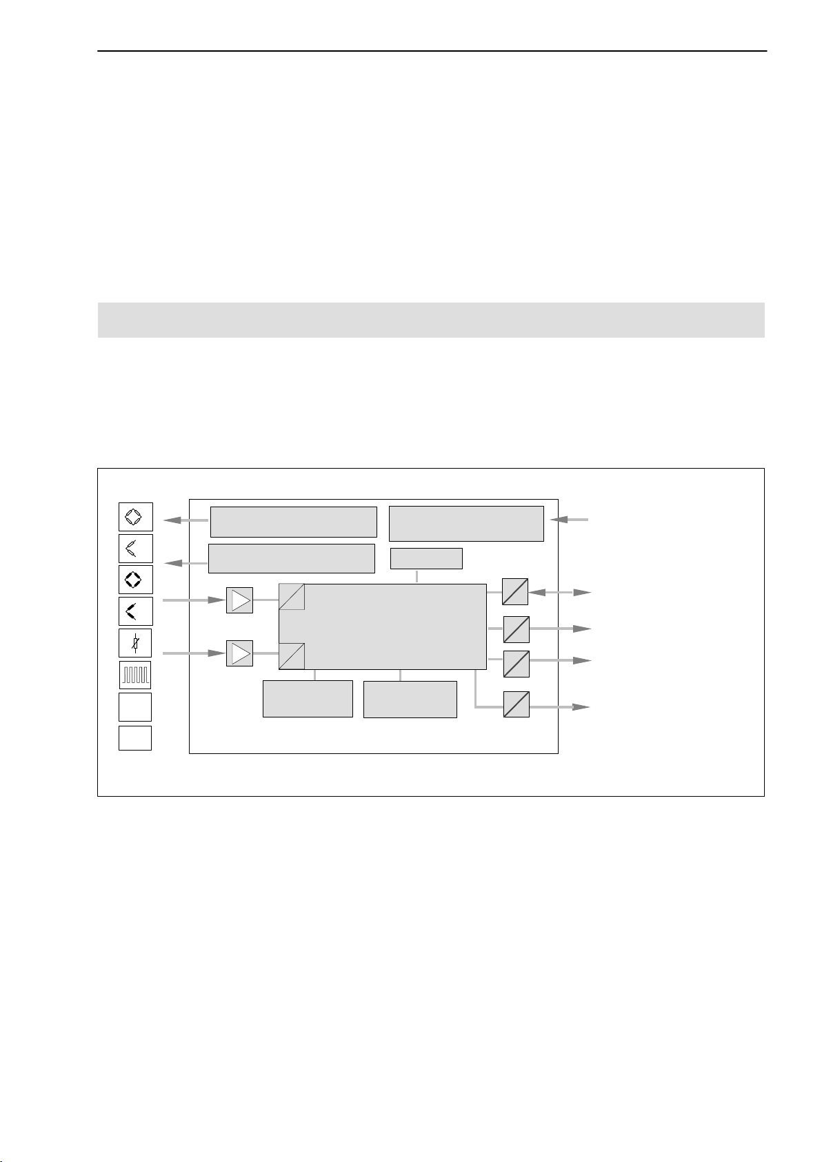
The MP85A process controller from the PME product line is a twin-channel
amplifier, suitable for connecting transducers of different technologies. The
MP85ADP and MP85ADP-S also have a PROFIBUS interface in addition to
the ETHERNET and CAN interfaces.
11
"10V
SSI
Carrier-frequency bridge
excitation voltage 4.8 kHz
Power supply for active
transducers 5 V or 24 V
A
D
Intelligent signal conditioning
and powerful algorithms for
A
D
Keyboard and
display
monitoring fitting
memory card
MP85A(DP)/MP85A(DP)-S
Voltage supply,
electrically isolated
EEPROM
MMC/SD
μP
24 V
Control inputs and
outputs, or switch test
inputs
CANopen interface
Ethernet interface
PROFIBUS DP interface
(for MP85ADP and
MP85ADP-S)
Fig. 1.1: Block diagram of the MP85A process controller
The PME Assistant provides a simple and free user interface for device parameterization under MS Windows.
This needs an Ethernet (crossover) cable (order no. 1-KAB2392) for direction
connection to a PC or a USB → CAN interface converter (when using a CAN
interface), which must be ordered separately (order number: 1-PMESETUPUSB).
All device parameters can be set with this software. The Ethernet or CAN bus
interface is set directly at the device.
Other devices in the PME product family can also be set up with this software
(MP01 ... MP70).
A2392−5.0 en HBM
Page 12

12
MP85A process controller
1.3 About this documentation
MP85A process controller documentation comprises
− this operating manual, which mainly describes setting up the hardware
(transducer, device and PC with software).
− PME Assistant online Help and add-on software modules
describing device setup and function via software
− a separate operating manual with an object dictionary and an interface
description for Ethernet, CAN and PROFIBUS communication
− a quick start guide for fast commissioning of the MP85A process controller
and all software modules
− a quick start guide for the whole FASTpress suite, i.e. for all software
modules and the MP85A process controller
A2392−5.0 enHBM
Page 13
MP85A process controller
2 MP85A(DP)(-S) installation/removal (basic diagrams)
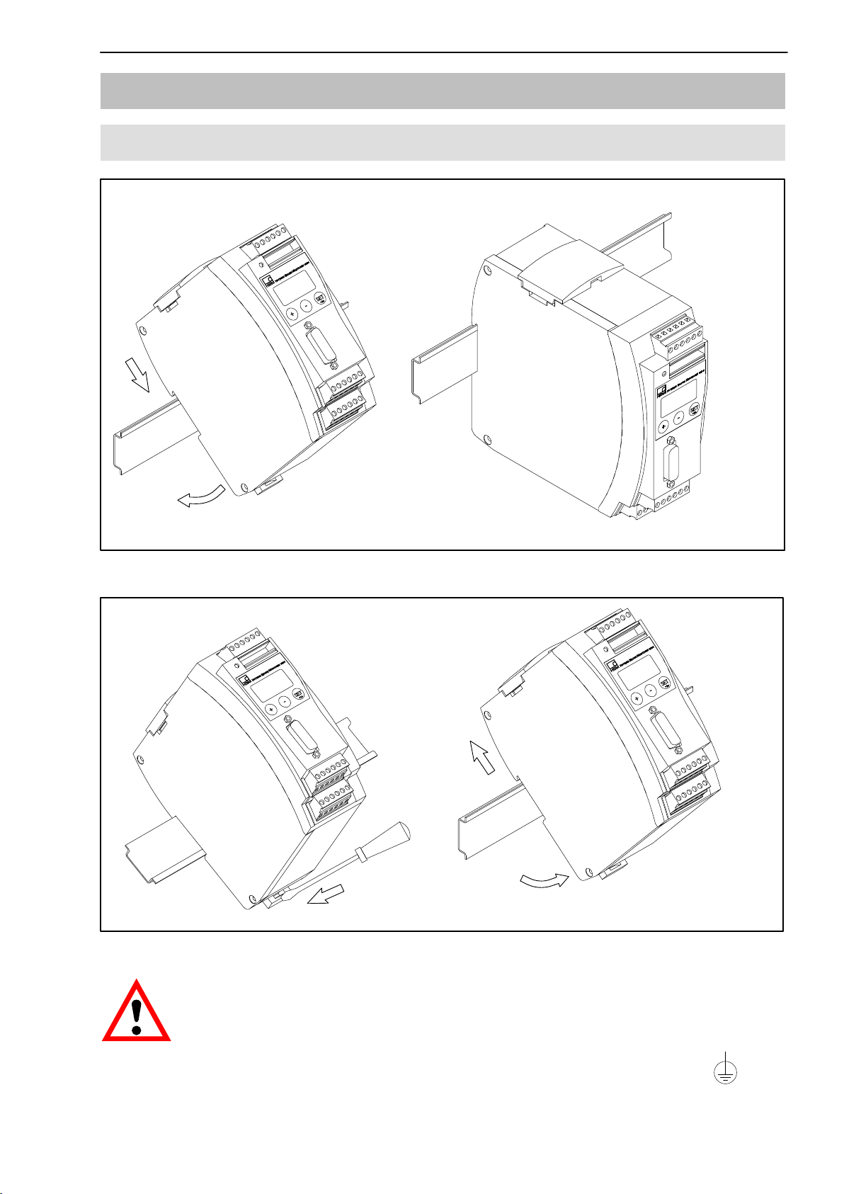
2.1 Mechanical installation
13
Fig. 2.1: Mounting on a DIN rail
Fig. 2.2: Removal
CAUTION
The DIN rail must be connected to grounded conductor potential .
A2392−5.0 en HBM
Page 14
14
MP85A process controller
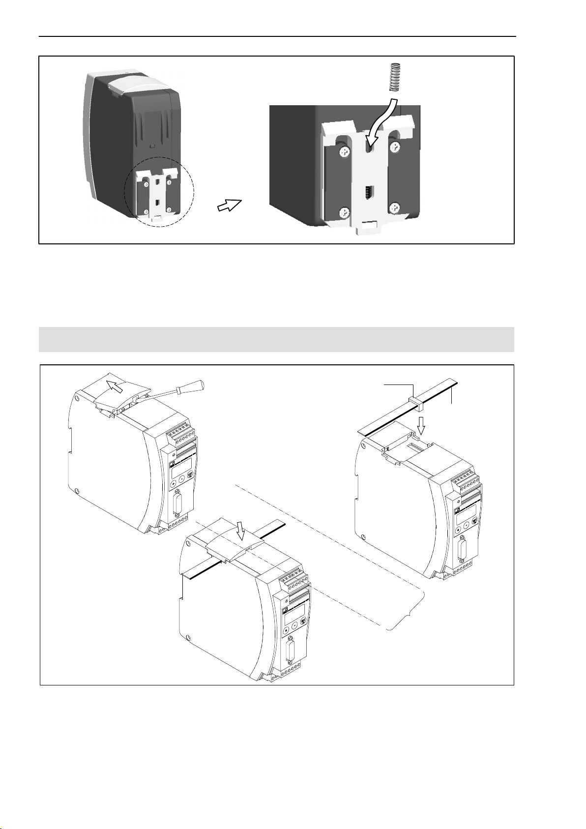
Fig. 2.3: Fitting a second spring for a more stable MP85A process controller
mounting on the DIN rail
2.2 Connecting several devices
Flat ribbon cable female connector
Subsequent devices are
interconnected via this
connector.
1.
3.
Color-coding on
Pin 1
2.
58 mm
Recommended gap for
flat ribbon cable female
connectors
Fig. 2.4: Connecting the flat ribbon cable
Up to four MP85A process controllers can be connected via one flat ribbon
cable. This cable takes care of local supply voltage, CAN bus connection and
carrier frequency synchronization between the devices.
A2392−5.0 enHBM
Page 15
MP85A process controller
3 Electrical connection
WARNING
Comply with the safety instructions before starting up the device.
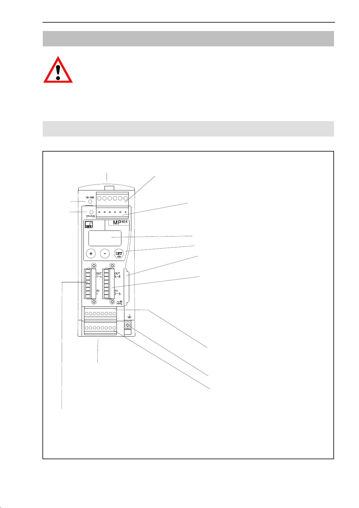
3.1 Overview of MP85A/MP85A-S functions
Local connection of CAN bus, supply voltage and synchronization between
modules
LED 1
LED 2
Screw terminal 1:
Voltage supply and CAN bus,
synchronization
Screw terminal 2: (same assignment as
screw terminal 1)
CAN adapter for PC/laptop connection,
parameterization via CAN bus
2-line LC display
Control keys
Module for MultiMediaCard (MMC) /
SD Card
15
Screw terminal 4:
4 electrically isolated control input or
switch-check inputs (24 V level,
relative to input ground screw terminal
3)
4 electrically isolated control outputs
(24 V level, power supply via screw
terminal 3)
Screw terminal 5:
Transducer connection channel x
Connection 7:
RJ45 socket for Ethernet
connection (see Page 46)
Screw terminal 3:
1 electrically isolated control input or switch test input (24 V level) incl. input
ground,
4 electrically isolated control outputs (24 V level), external supply feed for
control outputs and incremental or SSI transducers
including transducer excitation
Cable shield connection for
transducers
Screw terminal 6:
Transducer connection channel y
including transducer excitation
A2392−5.0 en HBM
Page 16

16
MP85A process controller
3.2 Overview of MP85ADP/MP85ADP-S functions
Local connection of CAN bus, supply voltage and synchronization between modules
Screw terminal 1:
Voltage supply and CAN bus,
synchronization
LED 1
LED 2
Screw terminal 2: (same assignment as
screw terminal 1)
CAN adapter for PC/laptop connection,
parameterization via CAN bus
2-line LC display
Control keys
Module for MultiMediaCard
(MMC) / SD Card
Connection 4:
9-pin sub-D socket for
PROFIBUS DP
connection
Screw terminal 5:
Transducer connection channel x
including transducer excitation
Cable shield connection for
Connection 7:
RJ45 socket for Ethernet
connection (see Page 46)
Screw terminal 3:
1 electrically isolated control input or switch test input (24 V level) incl. input
ground,
4 electrically isolated control outputs (24 V level), external supply feed for
control outputs and incremental or SSI transducers
transducers
Screw terminal 6:
Transducer connection channel y
including transducer excitation
A2392−5.0 enHBM
Page 17
MP85A process controller
17
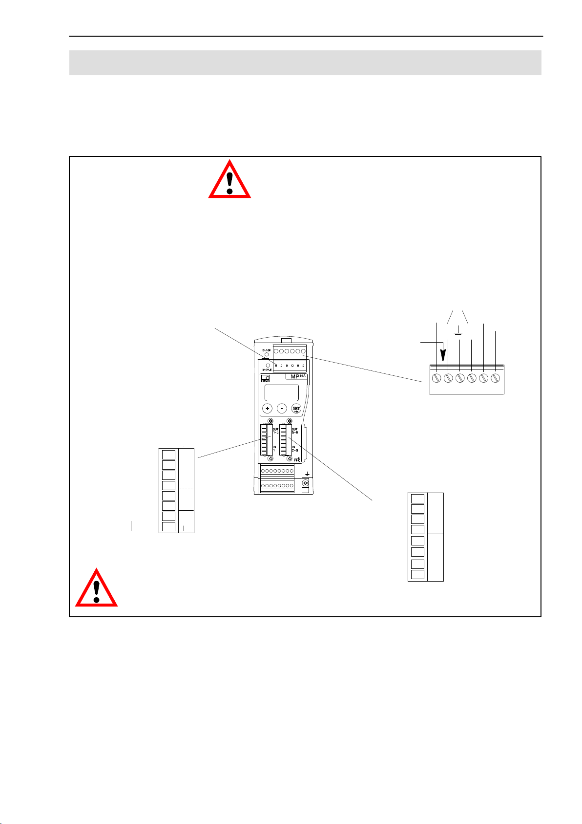
3.3 Supply voltage and control inputs/outputs
Four (MP85A/MP85A-S) or three (MP85ADP/MP85ADP-S) plug-in screw
terminals are available for connecting the power supply and the control inputs
and outputs. Control input/output functionality can be freely assigned with the
PME Assistant (menu: Digital inputs/outputs).
Connecting the power
supply:
The MP85A process controller must be connected to an
external supply voltage of 18−30 V (24 V
D Attach wire end sleeves to the voltage supply wire ends.
D Screw the wire ends to screw terminal 1.
D Insert the screw terminal into the top socket.
D Switch on the voltage supply.
Screw terminal 2
(CAN adapter; assignment as for
screw terminal 1)
WARNING
Labeling
nom
CAN
0 V
LH
).
24 V
SYNC
Screw terminal 3
(control inputs/outputs,
switch test inputs)
Out 1
Out 2
Out 3
Out 4
0 V
24 V
IN 1
IN
IN = digital input OUT = digital output
CAUTION
1
2
OUT
3
4
0V
24V
1
IN
Should the mains power fail in the MP85A process controller,
Screw terminal 4 (MP85A(-S))
(control inputs/outputs, switch test inputs)
Out 5
Out 6
Out 7
Out 8
Screw terminal 1
(CAN bus voltage supply,
synchronization)
5
6
OUT
7
8
IN 2
IN 3
IN 4
IN 5
2
3
IN
4
5
all control outputs will be set to 0 V.
Fig. 3.1: Screw terminal assignment
The screw terminals are coded to stop them being fitted into the wrong
socket. The sockets have coding tabs, screw terminals 1 and 2 have coding
pins.
The coding lugs are broken off for screw terminals 3 and 4. The contact
spacing is also different in each case for screw terminals 3 and 4, as well as 5
and 6.
A2392−5.0 en HBM
Page 18
18
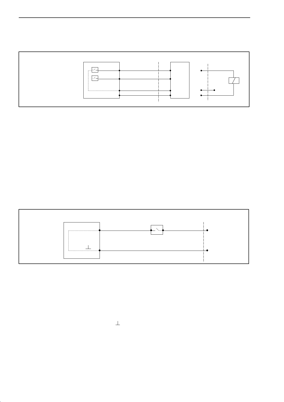
3.3.1 External supply voltage for control outputs
Example: PLC connection (p-switched)
MP85A process controller
MP85A process controller
Screw terminal 3
OUT3
OUT1
24 V*
0 V*
max. 0.5 A
PLC
Relay
max. 0.5 A
24 V
0 V*
Fig. 3.2: Connection to a PLC
The control outputs are available at screw terminals 3 and 4 and are electrically isolated from the internal supply voltage:
• at screw terminal 3: control outputs 1...4
• at screw terminal 4: control outputs 5...8 (MP85A(-S) only)
)
*
The control outputs must be supplied with an external voltage (ground and
24 V) via screw terminal 3. This external voltage is electrically isolated
from the measurement ground.
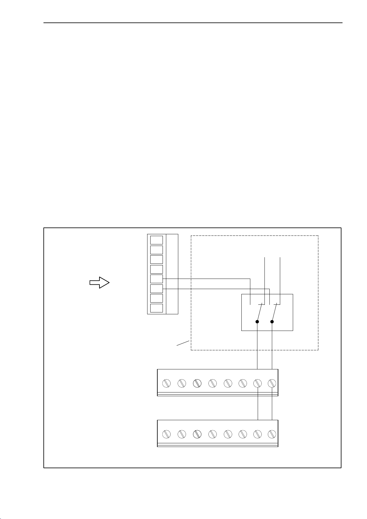
3.3.2 Reference potential for control inputs / switch test inputs
MP85A process controller
Screw terminal 3
IN 3
IN
Fig. 3.3: Connection of control input / switch test input
Switch event / test specimen
24 V (10 ... 30 V)
0 V
The control inputs are available at screw terminals 3 and 4 and are electric-
ally isolated from the internal supply voltage and from the control outputs.
• at screw terminal 3: control input 1
• at screw terminal 4: Control inputs 2...5 (MP85A/MP85A-S only)
An external reference potential (
IN ), to which the control input signals relate,
must be connected for the control inputs.
The MP85A process controller digital inputs are flank controlled by
transition from 0V to control voltage (e. g. 24V). The set digital input
function is only implemented once with the rising flank. The subsequent
permanent application of the control voltage does not cause a further
action.
A2392−5.0 enHBM
Page 19

MP85A process controller
19
3.4 Transducer
Two transducers can be connected to screw terminals 5 and 6, independently
of one another. The two measurement channels are parameterized using the
PME Assistant (menu: Transducer).
3.4.1 Synchronization of carrier frequencies
Synchronization prevents interferences occurring due to small differences in
the carrier frequencies of the individual amplifiers, i.e that amplifiers disturb
each other.
Synchronization is advisable for transducers with carrier frequency excitation
when
D the transducer cables of several devices run side by side
D the measuring points are unshielded and are close together
Even if devices work without a CAN bus, the flat ribbon cable should always
be used for synchronization between them, see Section 2.2 on Page 14.
WARNING
To synchronize several devices, declare one device as master and set all
other devices as slaves. Setting is implemented via the PME Assistant
program (menu: Basic settings −> Hardware synchronization).
A2392−5.0 en HBM
Page 20
20
MP85A process controller
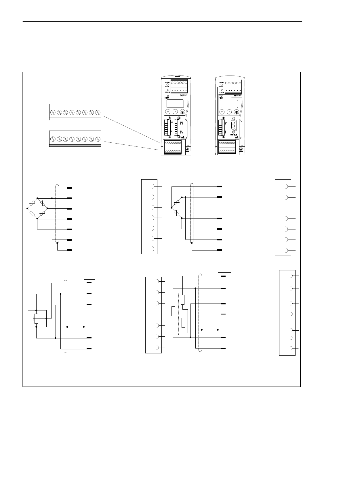
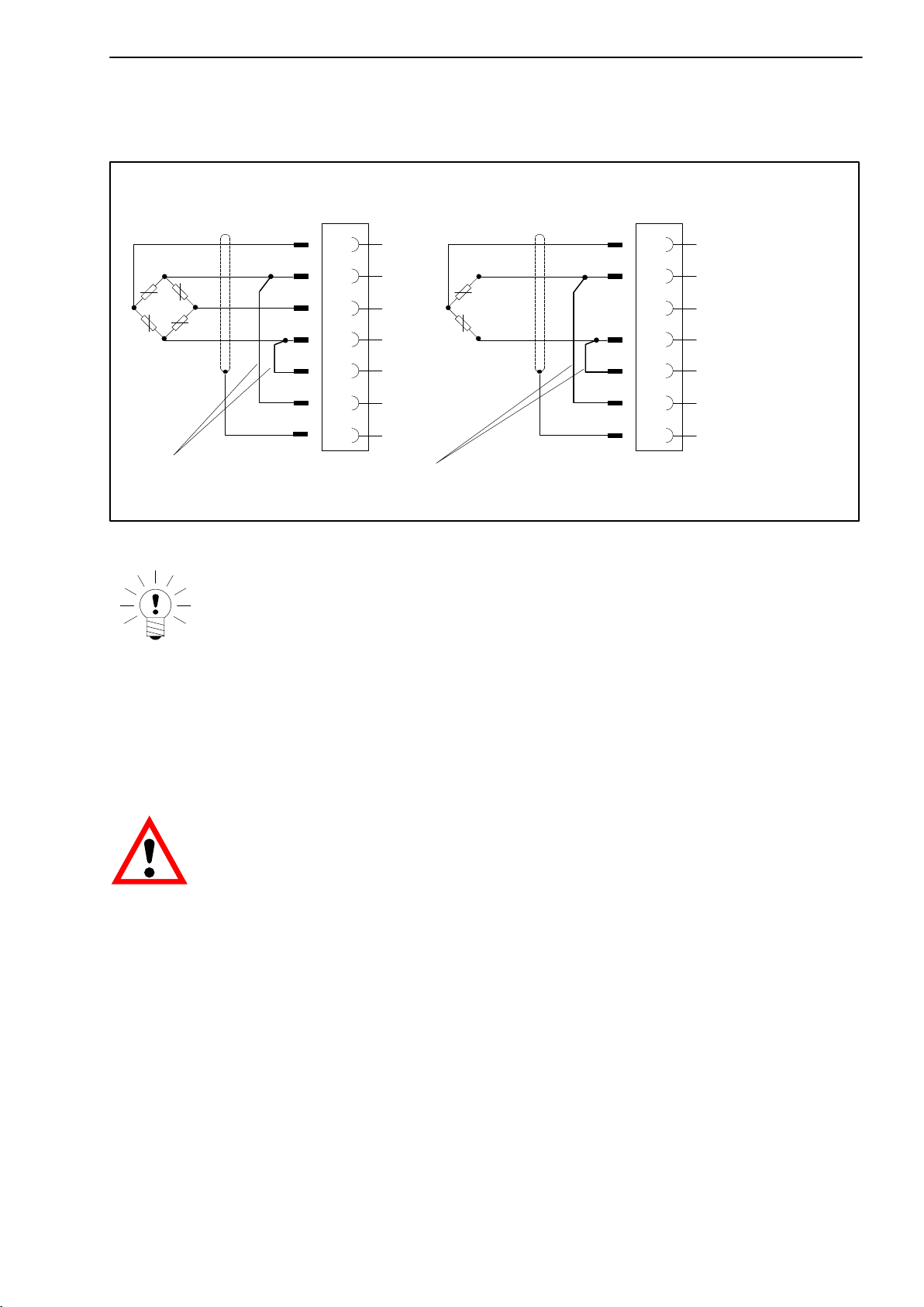
3.4.2 SGs, displacement transducers, potentiometric and LVDT sensors
In “carrier-frequency amplifier” mode, the following transducer types can be
connected:
Screw terminals 5 and 6
for transducer connection
SENSOR X
18
SENSOR Y
18
SG and inductive full bridges,
piezoresistive transducers
wh
Measurement signal (+)
bk
Bridge excitation
voltage (−)
rd
Measurement signal (−)
bu
Bridge excitation
gn
voltage (+)
Sense lead (+)
gy
Sense lead (−)
ye
Cable shield
MP85A(-S)
1
2
6
4
5
3
Hsg.
MP85ADP(-S)
SG and inductive half bridges
wh
Measurement
signal (+)
bk
Bridge excitation
voltage (−)
bu
Bridge excitation
voltage (+)
gn
Sense lead (+)
gy
Sense lead (−)
ye
Cable shield
1
2
4
5
3
Hsg.
Potentiometric transducers
Measurement
signal (+)
Bridge excitation
2
1
3
voltage (−)
Bridge excitation
voltage (+)
Cable shield
Sense lead (+)
Sense lead (−)
*)
1
2
4
Hsg.
5
3
LVDT transducer
Measurement
signal (+)
Bridge excitation
voltage (−)
Bridge excitation
voltage (+)
Measurement
signal (−)
Cable shield
Sense lead (+)
Sense lead (−)
1
2
4
6
Hsg.
5
3
Cable color code:
wh= white; bk= black; bu= blue; rd= red; ye = yellow; gn= green; gy= gray
*)
half bridge function
Fig. 3.4: Connecting different transducers in “carrier-frequency amplifier” mode
When connecting a transducer in four-wire configuration, the sense lines must
be connected to the appropriate bridge excitation circuit (Pin 3 with Pin 2 and
Pin 5 with Pin 4). With cable lengths >50 m, a resistor with half the value of
the bridge resistance (RB/2) must be connected instead in each sense lead of
the transducer.
A2392−5.0 enHBM
Page 21
MP85A process controller
If the transducers are calibrated in a six-wire circuit, resistors must be activated directly into the sense lead if cable lengths are >50 m.
21
Four-wire connection:
full bridge
wh
bk
rd
bu
ye
1
2
4
5
3
Hsg
6
.
Four-wire connection:
half bridge
wh
bk
bu
gn
gy
ye
1
2
6
4
5
3
Hsg
.
Feedback bridges for four-wire configuration
Cable color code: wh= white; bk= black; bu= blue; rd= red; ye = yellow; gn= green; gy=
gray
Fig. 3.5: Transducer connection in a four-wire-configuration
NOTE
Use standard HBM cables or other shielded, low-capacitance measurement cables for connecting the transducers. Connect the shield of each
transducer cable via as short a line as possible (t5 cm) and a flat
connector (4.8 mm; “Faston”) on the right next to screw terminal 6.
Otherwise EMC protection is not ensured.
CAUTION
Line break detection
MP85A process controllers have line break detection for the connected transducers.
The excitation voltage lines and the measurement signal leads are monitored.
With sense leads, a wire break is only reported as a fault if both lines are
broken; with measurement signal leads and excitation voltage leads, the
break of a single line is also reported as a fault. When a single wire breaks in
a sense lead, the measured value displayed is too high.
This also means that if the connection is faulty (for example, when full bridges
or half bridges are connected in four-wire configuration and the feedback
bridges are missing) an error message appears (display: Transducer error).
A2392−5.0 en HBM
Page 22
22
MP85A process controller
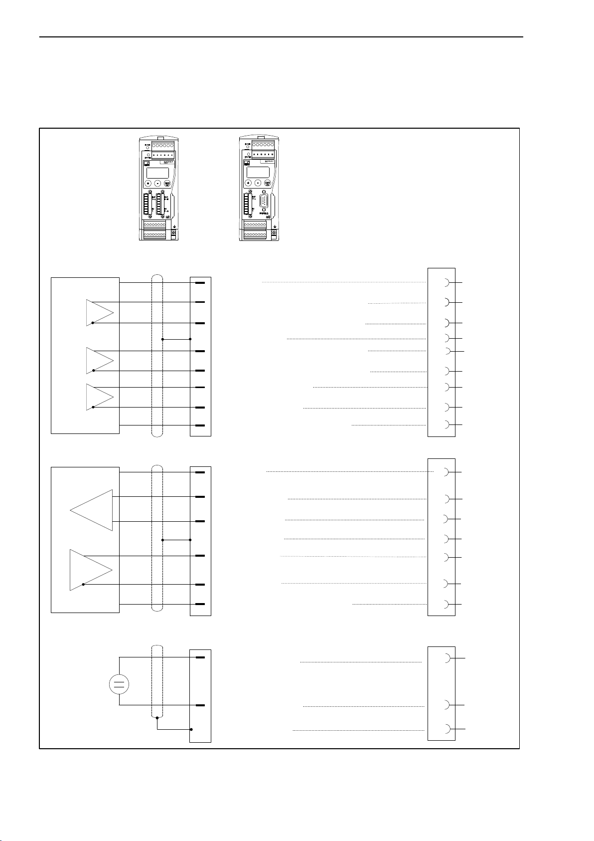
3.4.3 Incremental, SSI and DC sensors
In “Incremental encoder, SSI transducer or DC voltage transducer” mode, the
following transducer types can be connected:
MP85A(-S)
MP85ADP(-S)
Pulse counters, incremental transducers (symmetrical signals, TTL level, 5V)
Ground
f1, 0
f1, 0
f2, 90
f2, 90
o
o
o
o
Measurement signal F1 (+), 0°
Measurement signal F1 (−), 0°
Cable shield
Measurement signal F2 (+), 90°
Measurement signal F2 (−), 90°
Zero index, Ix (+)
Zero index, Ix (−)
Supply voltage +5 V/+24 V
Hsg.
7
6
1
5
3
4
2
8
Transducers with an SSI interface (symmetrical signals, TTL level, 5V)
Ground
Clock, Cl (+)
Clock, Cl (−)
Cable shield
Data, D (+)
Data, D (−)
Supply voltage +5 V/+24 V
DC voltage sources ("10 V)
U
Measureme
nt signal (+)
Measureme
nt signal (−)
Cable shield
7
6
1
Hsg.
5
3
8
5
3
Hs
g.
Fig. 3.6: Active transducer connection
A2392−5.0 enHBM
Page 23
MP85A process controller
23
A supply voltage is available at screw terminals 5 and 6, pins 7 and 8 for
feeding incremental encoders, transducers with an SSI interface and sensors
with voltage signal.
An internal or external power supply can be selected via switch S1. The
device must be open to do this (see Chapter 4).
• Transducer supplied from MP85A process controller:
Transducer supply voltage 5 V "10%, 150 mA max. (for both channels
together). The power supply is then not electrically isolated from the meas-
urement system.
• Transducer supplied from an external power pack:
At screw terminal 3, pins 5 and 6, a voltage of between 10 … 30V
DC
(nominally 24VDC), is supplied, including ground. A current of max. 300 mA
(for both channels together) can then be drawn at screw terminals 5 and 6,
pins 7 and 8.
This external supply voltage is electrically isolated from the measurement
ground and simultaneously feeds the digital control outputs.
Screw terminal 3
GND_int 5 V_int
external
power
supply
GND_ext
24 V_ext
5
6
S1
Internal MP85A
connection
78
Screw terminal 5
GND +5 V (int) / 24 V (ext.)
Screw terminal 6
78
Fig. 3.7: Active transducer power supply (basic diagram)
A2392−5.0 en HBM
Page 24
24
MP85A process controller
CAUTION
The differential signal of the measurement signal and the zero index signal must each be minimum 1.2 V.
The voltage to measurement ground must not exceed 14 V in any line. If
necessary, the voltage must be reduced via a voltage divider.
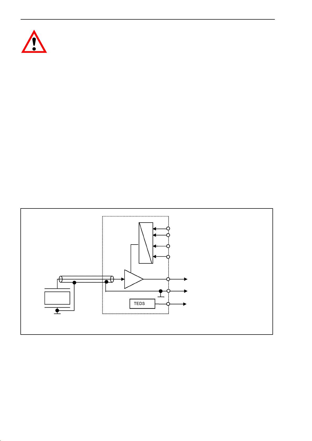
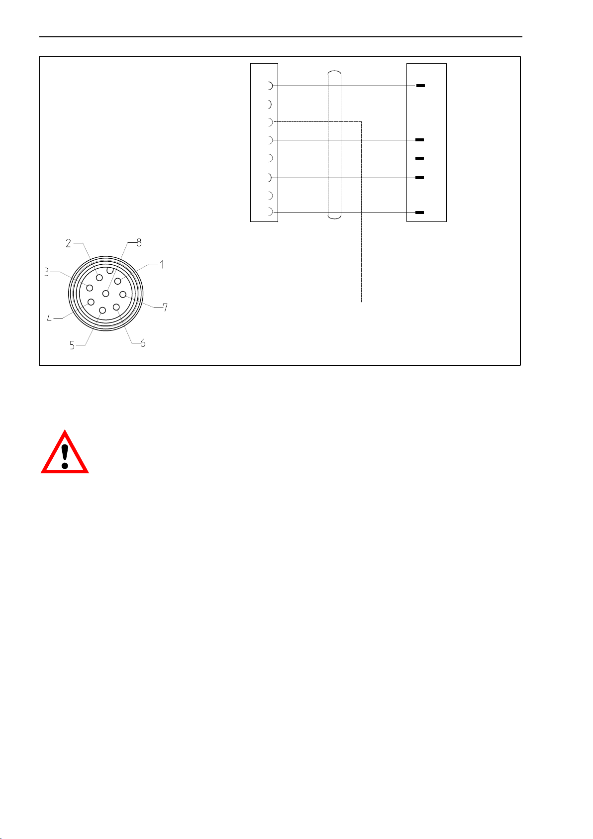
3.4.4 Piezoelectric measurement chains
The inline charge amplifier model CMA or CMD is required for operating
piezoelectric sensors on the MP85A process controller. The charge amplifier
is supplied externally with 24 VDC and is available from Pin 7 and 8 of the
screw terminals 5 and 6 of the MP85A process controller (see Chapter 3.4.3,
Active sensors, Fig. 3.7).
Internal or external voltage in the MP85A process controller can be selected
via switch S1. The device must be opened to do this (see Chapter 4) and the
switch S1 set to “24V external”.
Supply voltage
Piezoelectric
force transducer
CMA charge amplifier
18 to 30 V
0 V
DC
RANGE 1 / RANGE 2
MEASURE / RESET
Output voltage
−10 ... +10 V
0 V
DC
TEDS
DC
DC
Fig. 3.8: Block diagram of the piezoelectric measurement chain
The MP85A process controller measurement channel must be set to 10 V
(PME Assistant menu: Transducer). A reset on the charge amplifier must be
carried out before starting a measurement (Pin 3) MEASURE / RESET. With
an input voltage of 0 V at PIN 3, the charge amplifier is in the measurement
A2392−5.0 enHBM
Page 25

MP85A process controller
25
mode MEASURE. If a voltage of 24 V is present at PIN 3, the charge amplifier
switches to RESET.
TIP:
The reset signal can be generated externally or via the MP85A process
controller. To do this, the process signal “Reset piezo sensor” must be set to a
digital output of the MP85A process controller (PME Assistant, menu: Digital
outputs, circuit logic: positive).
TEDS:
The charge amplifiers have TEDS functionality for the voltage input which is
available in MP85A process controller from hardware version V1.07. When
operating without TEDS, the measurement ground (charge amplifier, Pin 6)
must be connected directly to Pin 3 of the MP85A process controller. The
yellow cable (TEDS) is therefore not required.
The charge amplifier has a measuring range selection RANGE1 / RANGE2.
Selection is via Pin 2 of the charge amplifier. The switching signal can be
supplied by an external control or the digital inputs of the MP85A process
controller. If a voltage of 0 V is present at Pin 2, measuring range 1 (100%
F
) is active at the charge amplifier.
nom
TIP:
The CMA charge amplifier gives you the option to zoom into a second measuring range (20% of the nominal (rated) force = 100% output span). A voltage
of 24 V
must be applied at PIN 2 for this.
DC
The changed measuring range must also be set in the MP85A process
controller, either automatically via the TEDS function or using the scaling
option of the input channel.
A2392−5.0 en HBM
Page 26
26
MP85A process controller
Supply voltage 0 V (GND).....
RANGE 1 / RANGE 2 (CMA only).....
MEASURE / RESET.....
TEDS.....
Output signal −10 ... +10 V.....
Measurement ground.....
Do not assign !.....
Supply voltage 18 to 30 V DC
M12 x 1, 8-pin
1)
Operating on a SELV circuit (separated extra-low voltage)
1)
1
2
3
4
5
6
7
8
.....
CMA/CMD
MP85A process controller digital OUT (Reset piezo
sensor); screw terminal 3 or 4 (output)
white
yellow
gray
pink
red
MP85A process controller
Sensor x/y
(Screw terminals 5 and 6)
7
3
5
2
8
Fig. 3.9: Connection of the piezoelectric charge amplifier CMA/CMD
CAUTION
After RESET, the charge amplifier output is set to zero, but this does not
mean that the machine generating the force is force-free. Make sure that
the force transducer is not overloaded, even though the output signal is
still in the −10 − +10 V range.
Once all the force is removed, a negative voltage signal is present with
the value of the voltage output for a RESET, without having to RESET
again.
Detailed information can be found in the operating manual “PACEline
piezoelectric force measurement chain CMC”.
A2392−5.0 enHBM
Page 27

MP85A process controller
27
3.5 TEDS-transducers (electronic data sheet)
3.5.1 TEDS connection
TEDS stands for “Transducer Electronic Data Sheet”. Transducers with electronic data sheets as per standard IEEE 1451.4 can be connected to the
MP85A process controller. This enables the automatic setting of the measuring amplifier: The transducer characteristics (electronic data sheet) are read
and translated into own settings and measurement can then start. A six-wire
configuration must be used for TEDS to be connected.
Fig. 3.10: MP85A process controller with TEDS technology
3.5.2 Parameterization with TEDS
If a transducer with TEDS, containing the parameterization data for a sensor,
is connected, this can be used to parameterize the MP85A process controller
automatically.
When the MP85A process controller is activated, it automatically detects
whether a TEDS is connected. When the transducer is replaced in the activated state, the new TEDS is also detected automatically.
To monitor TEDS functionality and to protect scaling from manual intervention, check the boxes in the TEDS dialog box in the PME Assistant
(menu: TEDS). TEDS functions can be enabled individually for each
channel. Using TEDS for piezoelectric measurement chains is described
in Section 3.4.4 .
NOTE
A2392−5.0 en HBM
Page 28

28
Set up with the PME Assistant
In the PME Assistant, choose the desired conversion unit from the selection
menu in the “TRANSDUCER” area. If instead you want to use the unit stored
in the TEDS directly, deactivate this function in the TEDS dialog box.
When the TEDS is activated, its scaling data will be read out and converted to
the required physical unit. Should the unit stored in the TEDS and the
required conversion unit be incompatible because they describe different
quantities (e.g. torque transducer connected, conversion unit is “N”), an error
message is generated and scaling does not take place.
If a scaling error is reported once the TEDS is activated, the reason may be
that the value range specified by the two characteristic curve points is so
great or so small, that the measured values cannot be displayed with the set
decimal places.
You then need to adapt the number of decimal places in the “Amplifier” area. It
may possibly help to change to a different power of ten, such as “N” to “kN”.
MP85A process controller
The PME Assistant displays this information for each channel in the “TEDS”
area with the “TEDS error status”. For an accurate analysis, it is advisable to
display the data stored in the TEDS. You need the TEDS Editor and suitable
hardware, e.g. the HBM TEDSdongle, to connect the sensors.
The data for the minimum and maximum bridge excitation voltage in the
TEDS is also checked.
If, instead of using the PME Assistant, you are parameterizing directly e.g. by
bus command, you must use Object 2122 to set the required conversion unit
before activating TEDS.
The available units match the selection list provided by the PME Assistant.
CAUTION
If several transducers are connected to an MP85A amplifier input in
parallel, their TEDS data cannot not be used as neither the error-free
reading out of parallel connected TEDS is ensured nor can a summation
of the individual parameters take place. In this case, ensure that the
fields in the TEDS dialog are not activated for the channels concerned.
3.6 Interfaces
Use the PME Assistant to set up and parameterize the device via the Ethernet
or CAN interfaces. In automatic applications, the devices are integrated into
the machine control via fieldbus interfaces.
A2392−5.0 enHBM
Page 29

MP85A process controller
3.6.1 Ethernet interface
An RJ45 socket for Ethernet connection is located underneath the MP85A
process controller as standard.
RJ45
29
Fig. 3.11: Ethernet connection
The device can also be integrated into an existing Ethernet network. It
supports speeds of 10 Mbit/s and 100 Mbit/s. The transmission speed is automatically adapted to the existing network. Category 5 or higher cables must
be used for this. This enables line lengths of 100 m to be implemented.
Fig. 3.12: Integrating the MP85A process controller into an existing Ethernet
network
Notes on operation in an Ethernet network
In order to avoid network problems, you should check the following points
before connection to an Ethernet network:
• Are the connected device addresses unique, i.e. no identical IP addresses?
A2392−5.0 en HBM
Page 30

30
MP85A process controller
• Does the network have sufficient reserves for the transmission of the
planned data or could the network load become too great?
• Are there nodes that could load the network through broadcasts, i.e. data
sent to all nodes?
In order to avoid disturbance of measurement operation by other network
nodes, you can also operate the devices in a separate network disconnected
from your company network. Connection to the company network would only
be necessary if external access to the measurement devices themselves is
necessary. If access to the generated data alone is required, you can implemented this with a PC connected between the networks − linked via one
network card to the devices and via a second network card to the company
network.
If the device is to be connected to the company network, we recommend the
use of a “Managed Switch” as these (higher quality) devices are by experience less susceptible to disturbances. The network with the measuring instruments and any PCs integrated in this network is then connected to the
company network via the Switch.
In order to achieve the best possible separation between the network with the
measuring instruments and the remaining company network, you can also use
a router that separates both networks and only transmits messages between
the two networks when necessary.
3.6.2 CAN interface
The CAN bus is connected via screw terminal 1. A maximum of 32 CAN
nodes can be connected in one bus segment (in accordance with the
CANopen specification).
The CAN bus needs a termination resistor of 120 Ω
node
. The maximum number of termination resistors the bus cable can have
on the first and last bus
is two. The MP85A process controller has an integrated termination resistor,
which is activated by toggle switch S2.
Low High
Device 1
Fig. 3.13: CAN interface connection
A2392−5.0 enHBM
Page 31

MP85A process controller
31
CAN-High
CAN connection
as per Fig. 3.13
CAN-Low
First device in
the bus cable
Connect the termination
resistor here (toggle
switch)
Do not connect the
termination resistor
Last device in
the bus cable
Connect the
termination resistor
here (toggle switch)
Fig. 3.14: CAN bus mode with several transducers (max. 32 as per standard)
NOTE
If the first or last device in the bus cable is not a PME device, a 120 W re-
sistor must be connected to each of these external devices.
The baudrate of all devices must be identical to that of the CAN master.
The baudrate must be reduced for greater line lengths according to the
CAN specifications.
3.6.3 PROFIBUS interface (MP85ADP/MP85ADP-S only)
On the front of the MP85ADP(-S) is a 9 pin D-Sub connecting socket for the
PROFIBUS connection.
GND
9
RS485-A
5
RS485-RTS
RS485-B
Vcc (5 V)
6
1
PROFIBUS
connection socket
Fig. 3.15: PROFIBUS connection as per standard
A2392−5.0 en HBM
Page 32

32
MP85A process controller
Installation:
• Connect the MP85ADP(-S) to a 24 V supply voltage and use the keyboard
or the Setup program to set the required PROFIBUS address.
• Connect the PROFIBUS line to the MP85ADP(-S). Make sure that termina-
tion resistors are connected on the first and last PROFIBUS nodes (there is
usually a slide switch on the housing of the PROFIBUS plug for this).
Example:
PROFIBUS plug PROFIBUS plug
First device in
the bus cable
PROFIBUS connector slide switch set to
“Resistor ON”
Fig. 3.16: PROFIBUS operation
Last device in
the bus cable
PROFIBUS connector slide
switch set to
“Resistor ON”
A2392−5.0 enHBM
Page 33

MP85A process controller
33
4 Switch settings / Replacing the battery
Changing the supply voltage for the active transducers
Use switch S1 to select either an internal 5 V supply or an external 24 V
supply as the supply voltage for the active transducers. The factory setting
is 5 V internal sensor supply voltage.
NOTE
The housing needs to be opened for this switchover. Therefore a change
must be made before the MP85A(DP) is mounted.
To set switch S1, proceed as shown in Fig. 4.1.
1
Unscrew the
cover
Switch S1 for the active
transducer supply voltage
2
S1
5 V
(int)
24 V
(ext)
Fig. 4.1: Opening the housing; position of switch S1 (basic diagram)
Example:
ON
12
34
5
means
6
Fig. 4.2: Switch convention
Termination resistor
The CAN termination resistor is activated and deactivated with switch S2
(see Fig. 4.3).
A2392−5.0 en HBM
Page 34

34
S2
ON OFF
MP85A process controller
Toggle switch S2 for the
termination resistor
Fig. 4.3: Switch for the CAN bus termination resistor (basic diagram)
Replacing the battery
The MP85A process controller has a real-time clock, which is fed by a
CR2032-type lithium battery. It can be removed from the battery holder and
replaced at the point shown in Fig. 4.4. The battery should be replaced about
every five years.
NOTE
The MP85A process controller must be removed from the DIN rail to
replace the battery.
1
Battery
for the
real-time clock
Unscrew the
cover
Fig. 4.4: Opening the housing; battery position (basic diagram)
2
CAUTION
Make sure that the battery is the right way round
A2392−5.0 enHBM
Page 35

MP85A process controller
Battery position
−
+
Fig. 4.5: Correct battery position
35
The buffer battery is only required for the device-internal real-time clock.
The device functions are not affected by the battery.
However, the time is also saved with the curve and results files. The correct time and data should therefore be set in the device (PME Assistant:
menu: Basic settings).
There is no automatic summer/winter time switchover.
A2392−5.0 en HBM
Page 36

36
MP85A process controller
5 Starting up/Setting up mode
To prepare the MP85A process controller for a measurement task, the
following requirements must be met and the relevant steps taken:
• You require an MP85A process controller and either the PME Assistant or
INDUSTRYmonitor program.
• The hardware must be set up: Transducer, MP85A process controller, PC
with software (from Section 5.2).
• The software must be installed (from Section 5.3)
To connect the MP85A process controller to a PC, you need:
− for Ethernet operation (Section 5.2.2 ):
• Ethernet crossover cable
− for CAN interface operation:
• CAN adapter (Section 5.2.3 ), either PCAN USB-to-CAN or PCAN card
(PCI or ISA)
The MP98A process controller must be connected to a PC via the Ethernet
cable or the CAN adapter. Once you have launched the software, you can set
up the MP85A process controller with the PME Assistant (Section 5.4).
In order not to invalidate subsequent statistics while in set up mode, the PME
Assistant (menu: Data storage) can be used to temporarily switch off the statistics processing.
TIP:
Detailed instructions are included in the PME Assistant Online Help. To call
the Help, the PME Assistant must be installed. For a quick guide to operating
the measurement system, refer to the FASTpress Suite quick start guide.
A2392−5.0 enHBM
Page 37

MP85A process controller
37
External
display
terminal
(option)
Sensors
Fig. 5.1: System configuration with the MP85A process controller
5.1 Operation
5.1.1 Device settings, measured values, process status, PROFIBUS,
memory cards, error types, firmware update, device backup
The MP85A process controller device display shows the measured values
and status information for measurement channels, process status, digital
inputs/outputs and parameter set backup; devices with PROFIBUS interface
also display the PROFIBUS status.
You can switch between individual displays and menus with the device
keyboard.
Use the device menu to set the Ethernet, CAN bus or PROFIBUS addresses.
In addition, a menu is available for device identification (serial number, firmware and hardware version, etc.) and for backing up the 31 Flash parameter
sets.
All other device settings are software set via the PME Assistant or the
INDUSTRYmonitor.
A2392−5.0 en HBM
Page 38

38
• Display in measuring mode:
MP85A process controller
Measured value
Unit
Status field
−18.0024
x
!
kg
• Function of the keys:
SET
1. Changing from measuring mode to
input mode
2. Choose the first parameter within
the group.
3. Confirm the entry
4. Return to measuring mode (press
for 2 seconds)
↑
Flashes in the status field if the parameter value can be edited
+
Selecting the
parameter/group
+
−
−
• Keys
Keep key pressed − Value runs continuously
Short key press − Advance by single value
During measurement, if you press
−
+
−
+
, the following will be displayed:
1. Measured values
• MVx Measured value for channel x
• MVy Measured value for channel y
2. Process status, “ProcStat”
• Alarm The last process was terminated via the alarm window
• O K The last process was OK
• N O K The last process was not OK
• Started A process has been started and not yet finished
3. Status of the digital inputs and outputs
The MP85A(-S) has 5 inputs and 8 outputs.
The MP85ADP(-S) has 1 input and 4 outputs.
• Input
set not set
A2392−5.0 enHBM
Page 39

MP85A process controller
39
• Output
set not set
4. PROFIBUS status (MP85ADP and MP85ADP-S only)
BD_SEAR (baudrate search)
WT_PARM (waiting for parameterization)
WT_CONF (waiting for configuration)
DATA_EX (cyclic data traffic)
ERROR (bus error)
5. Status of memory card (MMC/SD Card)
The optional memory card can be used if necessary to store measurement
curves, measurement results and even parameter sets (measurement
programs).
You can use either an SD card or a MultiMediaCard (MMC) up to 2 GB. The
PME Assistant (menu: Data storage) can be used to select what should be
saved and which medium (memory card or PC).
Up to 300,000 measurement curves can be stored on a memory card with 1
GB storage capacity. In addition, up to 31 parameter sets in XML format and
up to 1000 parameter sets in binary format can be stored.
Parameter sets in XML format can be loaded into the -device via the front
panel keyboard. Binary parameter sets can be selected using the PME
Assistant or the interface.
CAUTION
Only use standard MMC cards, not SecureMMC, MMCplus
TM
bile
, SDHC (SD High Capacity), SDXC cards (SD eXtended Capacity)
TM
, MMCmo-
or equivalent cards. The data transmission speed is not increased, but
incompatibility problems could occur. MMC or SD cards must be formatted with FAT16, not with NTFS, otherwise they will not be recognized by
the MP85A process controller. If necessary, reformat the card.
The MMC/SD card should be defragmented or reformatted at regular intervals
to optimize the access times.
A2392−5.0 en HBM
Page 40

40
MP85A process controller
Display Significance
unused
No memory card
Init...
SET ³ STOP
Saving
Stopped
No data should be saved to the memory card.
Data should be saved to the memory when anything else appears
on the display.
The device has no memory card inserted.
The memory card is initialized automatically on insertion.
The memory card is ready for storage. Pressing SET changes the
status to STOP. The memory card can then be removed.
Data are being written to the memory card. Once writing is complete, the status changes to “Ready”; SET ³ STOP appears on
the display.
Before removing the memory card from the device, you must
press the SET key. This will close all the files and write the
FAT.
The display briefly shows the message “MMC/SD Disk Closed” or,
in the case of error, “MMC DiskClose Err”. The MMC/SD card then
switches to the “Stopped” status and can be removed from the device. If there is no more space left on the memory card, it automatically switches to the “Stopped” status. This status can only be left
when the memory card is removed from the device. Re-initialization then follows automatically.
6. Kinds of error
During measurement, the ! character in the status field (in measuring mode)
indicates an MP85A process controller error.
−
+
Errors are displayed successively (can be reached using
).
− ERROR x (relative to the SENSOR X screw terminal)
− ERROR y (relative to the SENSOR Y screw terminal)
SENSOR X
SENSOR Y
TIP:
The relevant device status is clearly displayed with an error overview in the
PME Assistant “Status overview” dialog. Open the dialog via the “Status”
button in the Measured value display window.
The meaning of the displays and possible corrective measures for error
messages are listed in the online help (use F1 to call the Help). Further valuable tips and setting assistants can be found in the FAQ section.
A2392−5.0 enHBM
Page 41

MP85A process controller
41
Status
NOTE
The possible error messages are summarized in Chapter 10, “Error messages”.
7. Firmware update (F-Update)
To update the firmware, use the program PME Update. A description of the
procedure can be found in the online help. The program can be used to
transfer a new firmware version to several devices simultaneously. In order
not to conflict with the processing of a process (no measurements or evaluations can be implemented during an update), you can specific from firmware
version 2.22 or higher that the firmware update is only implemented on the
device following manual confirmation (F-Update: Permitted!). If confirmation
does not occur within 15 minutes, no changes are made to the firmware.
The firmware update program is available on the System CD or can be downloaded from the HBM website.
We recommend saving the device settings (device backup) before any
updates.
8. Device backup
All MP85A process controller settings can be saved to MMC/SD card via the
integrated keyboard and then, e.g. transferred to another MP85A process
controller.
Using the device menu, all 31 Flash parameter sets, including all interface
settings of the MP85A process controller, can be saved to the memory card
A2392−5.0 en HBM
Page 42

42
MP85A process controller
as a backup (“S-Status Save”) and reloaded into the MP85A process
controller where necessary. When loading, you can select whether loading
should take place without interface parameters (“S-Status Restore”) or with
interface parameters (“S-Status Load-Com”), see Chapter 5.1.3. Confirm the
action by pressing the SET button. Progress is displayed as a % display in the
device display.
CAUTION
No measurements or evaluations are implemented during a device
backup and the response times of the device to the software or controllers take longer!
5.1.2 Overview of all groups and parameters
SET
+
Up
−
Down
+
−
CAN-BUS ETHERNET PROFIBUS ADD. FUNCTION
Baudrate MAC address Address
Address IP-Adr.1
MNGRP
Parameter overview
Groups
Ampl.Type
(amplifier type)
MNGRP
IP-Adr.2
IP-Adr.3
IP-Adr.4 SD/MMCLo
SubNetM1
(subnet mask)
SubNetM2
SubNetM3
SubNetM4
IPGatew1
IPGatew2
PrgVers
(firmware version)
SrNo
(serial number)
HW vers.
(hardware version)
MNGRP
SYSTEM-STATE
Backup Save
Backup Restore
Backup Load-Com
MNGRP
IPGatew3
IPGatew4
MNGRP
A2392−5.0 enHBM
Page 43

MP85A process controller
43
MNGRP: with
SET
, back to main group
SD/MMCLo:
Gives you the option of loading a parameter set (XML format only) that has
previously been stored on the MMC/SD card with the PME Assistant or
+
INDUSTRYmonitor. Use keys
and − to select the required parameter set.
IP gateway:
From firmware version 2.20, the gateway address can be entered for crosssegment device access in the Ethernet network.
System-state:
From firmware version 2.22, you can save the MP85A process controller
settings to an MMC/SD card or e.g. load them into another MP85A process
controller. “S-Status Restore” restores all settings, “S-Status Load-Com”
restores all settings except the addresses (CAN/Ethernet/PROFIBUS).
A2392−5.0 en HBM
Page 44

44
5.1.3 Setting parameters on the device
Measured
value
SET
2 secs
MP85A process controller
Groups
SET
CAN bus
SET
Baudrate
SET
↑
10kB
20kB
50kB
100 kb
+
−
PROFIBUS
ETHERNET
MAC address
+/−
SET
+
IP-Adr.1
125 kb
250 kb
+
−
Address
SET
500 kb
1000 kb
↑
1−127
+/−
−
SET
Address
Back to Main
GRP
↑
3−123
SET
+/−
IP-Adr.2
IP-Adr.3
IP-Adr.4
SubNetM1
+
SubNetM2
Back to Main
GRP
−
Parameter values
+
Select parameter
−
SubNetM3
SubNetM4
IPGatew1
IPGatew2
Flashes, if parameter value
↑
can be edited
Confirm entry:
+/−
=
+ −
or
SET
Back to measuring mode:
press
SET
2 secs
SET
IPGatew3
IPGatew4
Back to Main
GRP
A2392−5.0 enHBM
Page 45

MP85A process controller
45
Groups
ADD. FUNCTION
SET SET
Ampl.Type
PrgVers
+
−
SET
SrNo
HW vers.
SD/MMCLo
(ad)
Back to Main
GRP
+
MEAS. MODE
−
Save?
Meas. value
SET
↑
↓
0 − 31
SET
+/−
+
Yes
↑
No
SYSTEM-STATE
−
+/−
+
−
SET
Backup
Save
Backup
Restore
Backup
Load-Com
Back to Main
GRP
5.2 Hardware setup
5.2.1 Voltage supply / transducers
• Connect the power supply cable and the transducers to the module
(Sections 3.3 and 3.4).
CAUTION
Comply with the safety instructions!
• Switch on the power supply.
• The device runs a self-test (about 10 secs) and then, if this functions
properly, it is in measuring mode. During the self-test, the control
outputs stay at 0 V.
A2392−5.0 en HBM
Page 46

46
MP85A process controller
NOTE
If ! appears on the display or the status LED glows red, an error has occurred. Please refer to Chapter 10 “Error messages”.
• Connecting the bus system
To find out how to connect several devices to a bus, refer to Sections 2.2
(Page 14) and 3.6 (Page 28). Note that devices must be synchronized for
error-free operation.
5.2.2 Establishing the Ethernet connection
For an MP85A process controller to communicate with the PC, the device
must be connected to the PC. Use an Ethernet crossover cable (1-KAB239-2)
for direct connection. The connection (RJ45 socket) is located underneath the
MP85A process controller. When operating several devices in an Ethernet
network, we recommend the use of industrial Ethernet switches.
RJ45
As a minimum, category 5 cables with a maximum line length of 100 meters
are used for this.
Further information on connection setup and interface settings can be
found in the operating manual “CAN/PROFIBUS/Ethernet MP85ADP
FASTpress interface descriptions”.
A2392−5.0 enHBM
Page 47

MP85A process controller
47
5.2.3 Connecting the CAN adapter (USB)
• Should the PC not have its own CAN bus interface, you can use the CAN
to USB adapter (1-PMESETUP-USB).
• Plug the USB to CAN adapter into a free USB interface on your PC.
• Your PC will detect the adapter (Plug and Play).
A CD is included with the adapter. This CD contains the installation drivers
which are automatically installed during the installation of the PME
Assistant and when the USB to CAN adapter is connected.
5.3 Installing the PME Assistant software
The PME Assistant is installed using the supplied system CD. The latest
version can also be found on the HBM website: www.hbm.com −> Support −>
Software-/Firmware-Downloads.
System requirements
To run the PME Assistant software, you need a PC that meets the following
requirements:
• Intel Pentium 2 GHz processor or equivalent
®
• Windows
2000, Windows®XP ,Windows Vistat or Windows® 7
• Microsoft Internet Explorer 6.0 (or higher)
• RAM:
®
• 256 MByte for Windows
• 512 MByte for Windows
• 2 GByte for Windows Vistat or Windows
2000
®
XP
®
7
• Graphics card with a resolution of 1024 x 768 pixels
• 20 MByte free memory on the hard drive
• The NTFS file system is necessary if you are recording numerous proces-
ses and therefore more than 65,000 files may be generated on the PC during a test.
• Microsoft or 100% compatible mouse
• Suitable standard printer
• Interface: USB-CAN interface from PEAK or Ethernet interface
• The following fonts must be installed: Arial (TT), Courier, MS Sans Serif,
Small Fonts, Tahoma, Times New Roman (TT), Verdana and Wingdings.
®
The fonts are normally installed with Windows
A2392−5.0 en HBM
.
Page 48

48
MP85A process controller
NOTE
The minimum requirements listed above are sufficient if you are only
connecting one device. Suitable, more powerful PC hardware and more
main memory are necessary if you also wish to transfer result and curve
files from several devices to PC.
Further information can be found in the quick start guide “FASTpress
Suite”.
5.4 PME Assistant operation
Interface
type
Opens the
Setup window
192 168 169 10
Factory settings
for the interface
Scanning the bus
for connected PME
modules
Fig. 5.2 Start window
5.4.1 Using the Ethernet interface
Launch the PME Assistant program and enter the required interface connection in the Start window:
• In the Interface field, select “TCP/IP”. The PME Assistant now gives you
the option of using the preset IP address or setting a new one.
• The address cannot be assigned automatically via DHCP. So you must
make sure that the IP address of the MP85A process controller differs
from the address of the network being used in max. one segment.
A2392−5.0 enHBM
Page 49

MP85A process controller
49
• In the subnet mask, a zero must be set in this position. All other
segments in the subnet mask must be set to 255.
• Now use the “Add IP to device list” button to transfer the IP address of
the MP85A process controller to the device list.
Alternatively, you can also press the “Scan” button to run a bus scan. In
this case, all the devices found will be displayed in the device list.
• If several MP85A process controllers are connected to the Ethernet
network via a switch, for example, make sure that each address has only
been used once. If you do not know the settings, you can query them via
the MP85A process controller keyboard (see Chapter 5.1.2).
• Use the “Start” button to launch the PME Assistant. The MP85A process
controller automatically sets the transmission speed to 10 Mbit or 100
Mbit.
5.4.2 Using the USB interface
Launch the PME Assistant program and take the following steps to configure
the USB interface:
• In the Interface field, select “CAN”. The PME Assistant now gives you the
option of selecting the CAN network to be used.
• The baudrate in the CAN network must be the same. In the delivery
condition, the baudrate of the MP85A process controller is set to 1 MBit/s.
• If you select “Use as standard”, this network will be chosen automatically
the next time the system starts up.
• If several MP85A process controllers are connected to the CAN network,
make sure that each address has only been used once. If you do not
know the settings, you can query them via the MP85A process controller
keyboard (see Chapter 5.1.2).
• Click the “Scan” button. The PME Assistant now searches for devices
connected to the CAN network and includes them in the device list.
• Use the “Start” button to launch the PME Assistant.
A2392−5.0 en HBM
Page 50

50
5.5 Automatic version recognition
MP85A process controller
If MP85A process
controllers are recognized
that use a firmware not fully
supported by your version
of the PME Assistant, the
following message appears:
The firmware of the device can be determined via the display of the MP85A,
PME Assistant or the INDUSTRYmonitor program.
The latest PME Assistant is always compatible with all MP85A(DP)-(S)
devices.
The latest software and firmware versions can be found on the HBM website:
www.hbm.com −> Support −> Software-/Firmware-Downloads.
NOTE
5.6 Firmware update
The firmware update program is installed using the supplied system CD. The
latest program and firmware versions can also be found on the HBM website:
www.hbm.com −> Support −> Software-/Firmware-Downloads.
New functions are often implemented via firmware and can then be loaded
into existing devices.
A2392−5.0 enHBM
Page 51

MP85A process controller
NOTE
The device settings remain unchanged if the firmware is updated. However,
we recommend that all settings be saved via the PME Assistant to the PC
before an update.
51
Simultaneous update of several devices can be selected.
In order not to conflict with the processing of a process (no measurements or
evaluations can be implemented during an update), you can specific from
firmware version 2.22 or higher that the firmware update is only implemented
on the device following manual confirmation (F-Update: Permitted!). If
confirmation does not occur within 15 minutes, no changes are made to the
firmware.
5.7 Offline operation
In offline operation, the PME Assistant can be used without a connected
MP85A process controller to create a device setting (parameter set) and save
it in XML format to PC. The device setting can later be transferred to the
MP85A process controller.
The offline mode is started as follows:
− Open the PME Assistant and select the “Offline” interface.
− Select the required device type from the device list.
− Start the Assistant with the “Start” button.
The device settings can now be made without any connected MP85A process
controllers. In the “Save/Load parameters” menu, the settings can be saved to
PC or existing settings loaded for viewing and further processing.
A2392−5.0 en HBM
Page 52

52
MP85A process controller
6 Methods of measurement
A measurement start/stop can be implemented manually with the PME
Assistant in individual operation, externally via a digital input or via the field
bus interfaces.
When measurement starts, the measured quantities acquired by the sensors
are written as an x/y value pairs with a time stamp to the internal MP85A
process controller memory and rated as OK or NOK by means of defined
windows, an envelope curve or a tolerance band. In addition, limit value
monitoring can be included in the evaluation. The last measurement curve in
each case can also be instantly plotted and displayed. All processes can be
stored in the background, independently of this display.
6.1 Data reduction
y=f(x)
A measurand Y (force) is recorded and rated as a function of a measurand x
(displacement). The measurement points are also given a time stamp.
Advantage: Intelligent data reduction. Curve points are only generated when
there is a sufficiently large change to x or y. The values nx and ny are user-
selectable.
Fig. 6.1: Force/displacement-driven process curve determination
y=f(t)
A measurand on channel y is recorded as a function of time.
Advantage: There is no need for the X sensor (the displacement sensor on a
press, for example).
Condition: Reproducible feedrates, as otherwise the curve that depends on
them would be shortened or lengthened.
A2392−5.0 enHBM
Page 53

MP85A process controller
Fig. 6.2: Time-driven process curve determination
53
6.2 Classification
Classifying X or Y
Measured quantities on channel X, such as length, thickness and diameter or
channel Y, such as force, weight, torque, etc., can be divided into 5 groups
per window. This means that e.g. springs can be automatically sorted by
spring rate.
y
max
y
min
Fig. 6.3: Classifying the measurands of a tolerance window
NOTE
Statistics and classification can only be used when using the 31 Flash para-
meter sets, not with memory card or PC parameter sets.
6.3 Monitoring limit values in real time
A total of eight limit values can be assigned and monitored in real time for
channels X and Y. A switching signal of choice can be allocated to each limit
value. This allows a press, for example, to be switched over from “fast” to
“slow”. The circuit logic can also be inverted.
A2392−5.0 en HBM
Page 54

54
MP85A process controller
6.4 Masking out external tolerances
The MP85A process controller can suppress external tolerances, such as
those caused by the differing positioning heights of workpiece holders, e.g.
when the pin being press-fitted is touched. Displacement is set to zero at this
time and a second relative axis is drawn to which the coordinates of the evaluation elements now refer.
Reference point
Dynamic zero point, relative to the force trigger.
When the reference point is reached, displacement is set
to zero. The windows now relate to this zero point.
Fig. 6.4: Reference points for X relative reference of evaluation elements
6.5 Evaluation criteria
The MP85A process controller has different window types to allow a universal
evaluation of the various curve shapes using window techniques. Any mix of
these window types can be used for each measurement curve. An envelope
curve is available if the entire process is to be monitored without a gap.
Fig. 6.5: Evaluation method using tolerance windows
Thread-in window
This checks that the fitting partners thread in correctly and do not fit askew.
A real-time signal indicates that there is a thread-in problem (for example,
window exited at top) and this can be used by the press control to trigger the
return stroke of the press, for example.
A2392−5.0 enHBM
Page 55

MP85A process controller
Error during thread-in ! Force too great !
Real-time signal “Withdraw press”
55
Fig. 6.6: Online window
Process window
This window type checks the course of a curve in the window area.
The curve must run through the window as defined from the entry side to the
exit side, without violating any of the other window limits. The entry and the
exit sides are user-selectable (left, right, top, bottom, any).
Fig. 6.7: Process window
Block window
The block window monitors the block size and the block force of a press-fit
process. With this window type, the curve must enter at the given entry side
and must not exit the window. The entry side is user-selectable (left, right, top,
bottom, any).
Approved
block force
Approved block
size
Fig. 6.8: Block window
A2392−5.0 en HBM
Page 56

56
MP85A process controller
Thresholds
Thresholds monitor the process continuously in very restricted ranges. The
thresholds can be positioned vertically or horizontally. As an option for
machine safety, these evaluation elements can also monitor the process in
real time and signal the control via a digital output or the field bus.
y
y-threshold
x-threshold
x
Fig. 6.9: Thresholds
Envelope curve
The envelope curve continuously monitors the process in max. 4 adjustable
ranges. The process must enter the envelope curve on the one side and exit
on the other. The tolerance width of the envelope curve is freely selectable
and can therefore be adapted to process requirements. Evaluation takes
place at the end of the process.
y
x
Fig. 6.10: Envelope curve
Tolerance band
The tolerance band covers the complete process. The first to last measurement points must lie within the tolerance band in OK processes (in contrast to
the envelope curve which must be entered and exited). Evaluation takes place
at the end of the process.
A2392−5.0 enHBM
Page 57

MP85A process controller
y
x
57
Fig. 6.11: Tolerance band
Limit monitoring
From firmware version 2.22 and higher, the limit values can also be included
in the total result for process monitoring. This allows, e.g. minimum and
maximum values to be monitored at the start and/or end of a process. This
option is particularly useful in the evaluation methods “Envelope curve” and
“Tolerance band”: The following diagram monitors whether the start and end
of the measurement curve are lying in the yellow marked areas.
y
LV2
LV1
LV1 LV2
x
Fig. 6.12: Limit value monitoring
TIP:
The online help of the PME Assistant and additional software modules contain
an accurate description of all evaluation criteria with examples, diagrams and
Tips and Tricks. Start the PME Assistant and call help with F1.
A2392−5.0 en HBM
Page 58

58
MP85A process controller
6.6 Measurement programs (parameter sets)
A total of 31 measurement programs can be activated from the MP85A
process controller’s internal (flash) memory for 31 different workpieces. A
measurement program comprises a workpiece-specific parameter set
consisting of the settings of the amplifier for the sensor technology, measurement acquisition and storage, function assignments of the digital inputs/
outputs and the evaluation methods.
The parameter sets are loaded from the MP85A process controller flash
memory to the RAM via digital input/outputs, bus commands or the PME
Assistant programs (Chapter 8.6).
CAUTION
Parameter sets may only be switched after the end of a process, not
during a measurement. The next process may only be started once parameter set switching is complete (see Chapter 8.1, Machine control).
Internal buffer
(RAM):
Current
parameter set
Internal flash
(EEPROM):
31 parameter sets
+ factory settings
MMC/PC Card
1000 parameter sets
Fig. 6.13: Measurement program processing
In addition, e.g. as data backup, parameter sets can also be transferred to the
MMC/PC card of the MP85A process controller or connected computer. The
PME Assistant or INDUSTRYmonitor software is required for transfer to PC.
A2392−5.0 enHBM
Page 59

MP85A process controller
59
TIP:
The optional memory card (MMC(SD card) can store another 1000 parameter
sets in binary data format, in addition to the 31 parameter sets in XML data
format. The function and processing speed is identical for both file types.
Processing the system parameters
The system parameters include the basic settings, interface settings, passcode and settings for data storage and MP85A process controller statistics.
If the parameter sets from the internal Flash-EPROM are used, the system
parameters are identical for all 31 Flash parameter sets and only present
once in the MP85A process controller. If parameter sets from the MMC/PC
card or from PC are used, the system parameters are a component of the
respective parameter set and can therefore be different. This means that, e.g.
different memory settings can be implemented.
Flash
Amplifier settings
Digital IO
Evaluation (process evaluation)
Internal storage:
System settings, amplifier
settings, digital IO,
evaluation, data
storage/statistics
PC
MMC/SD
Amplifier settings
Digital IO
Evaluation (process evaluation)
System settings
Data storage/statistics
Fig. 6.14: Load parameter sets from external (PC/MMC/SD card) or Flash
A2392−5.0 en HBM
Page 60

60
MP85A process controller
7 Switch tester with MP85A(DP)-S EASYswitch
The functions for switch and haptic tests are only available in an
MP85A(DP)-S EASYswitch (switch test version).
7.1 Switch test
All the switching characteristics are recorded by the MP85A(DP)-S EASYswitch and evaluated according to specific features, such as actuating force,
release force, differential force and differential travel.
In addition to these mechanical parameters, the electrical switching point can
also be recorded. To do this, a switch testing type window is placed on the
marked points.
Fig. 7.1: Switch test
Up to 5 switches or switching elements can be checked and evaluated in one
procedure.
It is checked whether the switching of the switch lies within the corresponding
switch test window and whether the specified switching function (make/break)
is met.
The electrical check is implemented via the MP85A(DP)-S EASYswitch digital
inputs. Evaluation takes place at the end of the process.
A2392−5.0 enHBM
Page 61

MP85A process controller
61
NOTE
As the MP85ADP-S only has one digital switch test input, the (virtual) inputs 2
to 5 can be set via PROFIBUS commands and so the switch result displayed,
see MP85A interface description, Chapter 4.
The switch test inputs are available at screw terminals 3 and 4 and are electrically isolated from the internal supply voltage and from the control outputs.
• At screw terminal 3: Control input 1
• At screw terminal 4: Control inputs 2 … 5 (MP85A/MP85A-S only)
An external reference potential (
IN ), to which the control input signals relate,
must be connected for the switch test processes.
The MP85A process controller digital inputs are flank controlled by
transition from 0V to control voltage (e.g. 24V). The set digital input
function is only implemented once with the rising flank. The subsequent
permanent application of the control voltage does not cause a further
action.
MP85A process controller
Switch event / test specimen
IN 3
IN
Screw terminal 3
Fig. 7.2: Connection of control input / switch test input
24 V (10 ... 30 V)
0 V
Entry and exit sides are not needed for the switch test window type. They can
be monitored with additional process windows.
The switch coordinates displayed in the switch test window, i.e. the coordinates at which the switch changes state, are stored in the statistics. In addition,
“No switching” is signaled for OK or NOK, when the switch does not change
state or when switching is repeated because multiple switching occurs
(chatter).
Switch windows can also be parameterized as windows with defined
sequences. This ensures that on/off switchings are processed in the correct
sequence.
Evaluation follows at the end of the process, i.e. evaluation in real time cannot
be selected.
A2392−5.0 en HBM
Page 62

62
In the graphics, the switching instant for closing, IX:1, the number of the digital
input and 1 are displayed, as well as the symbol
Ix:0 is displayed with
input 1 has closed,
Fig. 7.1).
as the symbol. If, for example, the switch at digital
is marked on the curve and above it, I1:1 (see Fig.
MP85A process controller
on the curve; for opening,
7.2 Haptic test
The haptic test checks how the switch in this window changes its state, that is,
the “feeling” on actuation. The characteristic values required to do this can be
entered in the haptic test dialog box via the PME Assistant or INDUSTRYmonitor. Any combination or all the characteristic values listed can be tested.
The check is NOK as soon as one of the activated characteristic values is not
OK. The individual characteristic values are clearly shown in the graphic
below.
For the haptic test, the curve must enter and exit the window at the sides and
the window must always be square. It is not possible for the curve to enter or
exit the window at the top or bottom.
TIP:
To secure the process, additional process windows can be set up to evaluate
the process curve in real time and so assist machine protection. If the switch
is defective, limit force switch off is implemented with a reaction time of
approx. 2 ms.
Further information can be found in the online help of the PME Assistant
and the MP85A process controller interface description.
A2392−5.0 enHBM
Page 63

MP85A process controller
63
8 Communication with a control system
8.1 MP85A process controller in machine control
Digital inputs/outputs and the CAN, PROFIBUS-DP and Ethernet digital interfaces are available for embedding into a machine control. Both these cases
access the same MP85A process controller device functionality (object table).
Firstly, control commands can be exchanged between the MP85A process
controller and the machine control to ensure that production runs smoothly
and secondly, status information can be exchanged and signals given to the
machine operator. The following signals are available in real time as control
inputs/outputs (e.g. machine protection):
MP85A(DP)(-S) ⇒ digital input PLC
Process started / running
Process complete / valid
Process OK / NOK
Reset piezosensor
Result tolerance window x
Limit value …, channel …
Transducer test result
Error − channel x/y
Description
Shows whether a measurement is underway
Shows that the process has been implemented and the result is available. The next process may only be started once this signal has
been set
Shows the result of a process
Allows you to set a channel with piezoelectric
sensor to zero until measurement starts. This
suppresses the zero drift of this sensor
Individual windows can be specifically checked and evaluated with this message
The limit value status of this channel is output
Shows the result of a transducer test
A measurement error in the relevant channel
is present. This could be a transducer error
(e.g. in the connection), an error in the A/D
converter, the scaling, amplifier calibration
(initial calibration), TEDS error or a gross
overflow.
MMC/SD card memory full
Heartbeat
Transfer memory full
A2392−5.0 en HBM
The MultiMediaCard/SD card is almost full,
there are less than 5 MByte free. Replace the
card with a new card or delete files
The output switches with a frequency of 1 Hz
between ON and OFF, and can be used as a
watchdog function
The internal clipboard is almost full, there are
less than 16 kByte free. The message indicates a problem during saving of the measured
data, e.g. the specified PC could not be reached
Page 64

64
MP85A process controller
MP85A(DP)(-S) ⇒ digital input PLC
Set outputs per data word
Specify Flash parameter set
Parameter set is loading
Description
You can set the digital outputs via the SDO
object 2320 (hex), subindex 0. With this option, you can forward individual bits of the Bytes transferred with this object to the relevant
outputs
Allows you to specify the number of a parameter set loaded from the Flash: The parameter set number is output as a binary number
(Bit 0 to Bit 4).
Parameter sets loaded from the MMC/SD
card or PC cannot be queried
You can control the time required for loading a
parameter set with this function: The next process can only be started after switchover
which can take up to 200 ms, the MP85A process controller is only ready for measurement
after switchover. As long as the signal is active therefore, no new process can be started
PLC MP85A(DP)(-S) control input
Sensor zero balance
Shunt calibration
Transducer test
Load parameter set
Start/end process
Description
Enables a zero balance of the sensor
Activates the shunt resistance, e.g. to generate a defined signal
Implements a transducer test
Loads a parameter set. If, for example, only
three different parameter sets are required,
you can just use two inputs for parameter set
loading, Bit 0* and Bit 1*, you do not need to
assign all bits (parameter set 0 is the default
setting).
Specify via the signal condition whether the
zero value is retained during loading or whether the zero value from the parameter set
should be used.
Specify via data storage whether the device
name is retained during loading or whether
the device name from the parameter set
should be used
Use this input to start/end a process or the
measurement. If you enter further start, stop
or end conditions in the control settings, these
will also apply
A2392−5.0 enHBM
Page 65

MP85A process controller
65
PLC MP85A(DP)(-S) control input
Store/clear statistics
Switch test 1 ... 5
Stores the statistical data present in the RAM
in the Flash EPROM
For MP85A(DP)-S only:
Specify which inputs must be used for the test
with regards to a switch test. The inputs must
be connected to a supply voltage via the
switch to be checked so that the status can be
detected. As the MP85ADP-S only has one
digital input available, you can use the four
so-called virtual inputs: The status of the virtual input is set via a PROFIBUS command
(cyclical transmission).
The switching moments are also shown during a haptic test if an input is assigned
Description
There are two methods for process control:
1. With full storage of the process data, i.e. storing curves and results without
loss of data.
2. With a sequence optimized to the process, where, when there is a new
process, data storage is interrupted, so that the next process can be
started again even more quickly.
Both methods are described in the following sections, all signal diagrams are
based on positive circuit logic.
8.2 Test process sequence over time
a) Storing curves and results without loss of data
When you opt for the “without loss of data” storage method and want to save
the curves and/or results on the memory card or externally via the bus, the
following diagrams apply.
The ready signal is then only 1 again, if
− the process is completely finished,
− all the data have been fully stored and
− the device is ready to store the data for the next process.
A2392−5.0 en HBM
Page 66

66
Started
MP85A process controller
Start (ext. signal "Start" or
condition fulfilled)
Stop (condition fulfilled) or end, if ext. signal for end
condition is used and signal "End" is active
(internal) end condition fulfilled
(with ext. signal "End" this is
already fulfilled)
Ready
Running
Result valid
Process OK
Save (to RAM)
Offline evaluation
Time until stop (follow-up time, only possible when using
internal stop condition)
Measurement
Initialization (typ. 25 ms)
Reaction time (typ. 2 ms for external signal)
Fig. 8.1: Process data storage without loss of data
Signal is only set, if end
condition is fulfilled and
sufficient RAM space is
available for the next
measurement
Save to MMC/PC
NOTE
If the process data (curves and results) cannot be stored (because the
memory is full or faulty, for example), the next process cannot be started, as the MP85A process controller does not enable the Ready signal.
When saving data externally to a PC, the PME Assistant or INDUSTRYmonitor must remain open.
b.) Curve and result storage optimized to the process
When you opt for the “storage optimized to the process” storage method and
want to save the curves and/or results on the memory card or externally via
the bus, the following diagrams apply.
The difference between this and “storage without loss of data” is that the
Ready signal can be 1 again, even though the device is not yet ready to store
the new data.
A2392−5.0 enHBM
Page 67

MP85A process controller
67
This means that, following an immediate start of a new measurement, the
result and curve files will not be immediately transmitted. So you should only
choose this method if very fast processes have to be monitored and the
results and curves are merely used for spot checks.
Start (ext. signal "Start"
or condition fulfilled)
Stop (condition fulfilled) or end, if ext. signal for end
condition is used and signal "End" is active
(internal) end condition fulfilled
(with ext. signal "End" this is
Started
already fulfilled)
Ready
Running
Result valid
Process OK
Offline evaluation
Time until stop (follow-up time, only possible when using
internal stop condition)
Measurement
Initialization (typ. 25 ms)
Reaction time (typ. 2 ms for external signal)
Fig. 8.2: Sequence optimized to the process
Signal is only set, if end
conditions are fulfilled and
data is saved to RAM
Save to MMC/PC
Save (to RAM)
8.3 Transducer test
The transducer test can be triggered via the digital input or via the bus signal.
At low filter limit frequencies, the filter settling time must be waited before the
test. A pulse of minimum 5 ms duration at the digital input is necessary for the
transducer test. The result is typically available another 10 ms later.
A2392−5.0 en HBM
Page 68

68
Timing diagram for a transducer test
MP85A process controller
min. 5 ms
Input
Transducer test
Output transducer test
result
Typically 10 ms
1
0
8.4 Zero balance
The zero balance can be triggered via the digital input or via the bus signal. At
low filter limit frequencies, the filter settling time must be waited before the
zero balance. A pulse of minimum 5 ms duration at the digital input is necessary for the zero balance. The zero balance is completed another 5 ms later.
Timing diagram for a zero balance
min. 5 ms
Inputs
Zero setting
Input
START
Settling time, e.g. for a 100 Hz filter: 20 ms
1
0
8.5 Simulation of digital outputs
It can be helpful, particularly during start up or service, to check the system
components and processes downstream of the digital outputs through simulation and activation. The digital outputs of the MP85A process controller can be
activated/deactivated via software commands for this purpose.
The data word configuration to be transmitted for activating/deactivating the
digital outputs depends on the configuration of the data word bits on the digital
outputs.
A2392−5.0 enHBM
Page 69

MP85A process controller
The states of the digital inputs/outputs can be displayed in the “Measured
value display” menu.
Example: Activation of digital output 1
• Set digital output 1 in menu: “Digital outputs” to “Data word bit 0” (circuit
logic: positive).
• Send via a software command (e. g. “SDO terminal”) to address SDO 2320
Index 0 (hex) => 1 (dec): this sets the digital output 1 to High.
• Send data word 0 (dec) to address SDO 2320 Index 0 (hex): deactivates
digital output 1 again.
69
8.6 Parameter sets (measurement programs)
The MP85A process controller has the option to use 31 different measurement programs (parameter sets) and store them power failsafe in internal
flash memory. Another 1000 measurement programs can be saved to the
optional memory card (MMC/SD card).
CAUTION
Parameter sets can only be loaded when no process is running !
The device is only ready for measurement after loading. You can query this
via the signal “Parameter set is loading”.
Parameter sets saved to PC cannot be used by the device or software for the
ongoing operation. They must be saved to the Flash memory or the memory
card.
TIP:
In PROFIBUS-DP mode, the changeover of parameter sets to Flash and the
memory card can also be made in cyclic operation. Further information can be
found in the interface description of the MP85A process controller.
Typically, less than 200 ms are required for the activation of a new parameter
set. At very low filter limit frequencies, the filter settling time must be added. If
you use digital inputs for switching, the switchover occurs when the level
changes at the input (flank).
A2392−5.0 en HBM
Page 70

70
MP85A process controller
Load parameter set
(Level change with Bit0 ... Bit4)
Duration of switchover
Typ. < 200 ms
Parameter set is loading
Bit 4 Bit 3 Bit 2 Bit 1 Bit 0 Active parameter set
0 0 0 0 1 1
0 0 0 1 0 2
0 0 0 1 1 3
0 0 1 0 0 4
0 0 1 0 1 5
0 0 1 1 0 6
0 0 1 1 1 7
0 1 0 0 0 8
0 1 0 0 1 9
0 1 0 1 0 10
0 1 0 1 1 11
0 1 1 0 0 12
0 1 1 0 1 13
0 1 1 1 0 14
0 1 1 1 1 15
1 0 0 0 0 16
1 0 0 0 1 17
1 0 0 1 0 18
1 0 0 1 1 19
1 0 1 0 0 20
1 0 1 0 1 21
1 0 1 1 0 22
1 0 1 1 1 23
1 1 0 0 0 24
1 1 0 0 1 25
1 1 0 1 0 26
1 1 0 1 1 27
1 1 1 0 0 28
1 1 1 0 1 29
1 1 1 1 0 30
1 1 1 1 1 31
A2392−5.0 enHBM
Page 71

MP85A process controller
71
8.7 Evaluation/storage process times
The MP85A process controller FASTpress can reliably monitor and document
virtually all processes in industrial production. There can be up to 10 cycles
per second without process data storage).
The maximum number of process cycles is guided decisively by:
− the number of process curve measurement points (adjustable)
− the number of evaluation criteria (tolerance window)
− whether process data are to be stored (OK only, NOK only, all)
− whether several MP85A process controllers should be operated in network
(mains load)
− the performance of the storage medium
Some of these points can be specified via the PME Assistant or INDUSTRY-
monitor programs (menu: Set evaluation parameters and Data storage).
3 Windows
6 Windows
9 Windows
Process time / ms
Measurement points
Fig. 8.3: Device internal evaluation times (without process data storage)
A2392−5.0 en HBM
Page 72

72
Process time / ms
Measurement points
MP85A process controller
3 Windows
6 Windows
9 Windows
Fig. 8.4: Device internal evaluation times (with storage of all data to MMC/SD
card)
Data is transmitted to the memory card with a speed between 2 and
8 kBytes/second, subject to the size of the files to be transferred.
The total storage time results from the process time and the storage time on
the target computer.
CAUTION
If the process data are saved via Ethernet, the storage is dependent on
the network load. This must be taken into account with rapid process
cycle times.
Until all measured value curve data are saved to PC, the files have the file
extension .tmp. Once the data transfer is complete, the files are renamed with
the file extension C85 or D85. This means that downstream software can
clearly detect the storage status and only access the process data once
storage is complete.
Typical process times during production operation in combination with
PLC machine control
The following table shows the times that are approximately required when the
MP85A process controller exchanges cyclical data with a PLC via PROFIBUS, saves data to the MMC/SD card or transmits the data via Ethernet. With
INDUSTRYmonitor software running on the PC. The actually achieved values
depend on the hardware used (PC), the network components (switch) and the
network load. Times can range widely from process to process with Ethernet
in particular due to the latency time.
A2392−5.0 enHBM
Page 73

MP85A process controller
73
Configuration
(cyclical data also exchanged via PROFIBUS)
1 x MP85A process controller, 500 measurement points, save curves
and results to MMC/SD card
3 x MP85A process controller, 600 measurement points, save curves
and results to MMC/SD card
1 x MP85A process controller, 500 measurement points, output curves
and results via Ethernet, Ethernet connected directly
3 x MP85A process controller, 500 measurement points, output curves
and results via Ethernet, Ethernet connected via switch
3 x MP85A process controller, 600 measurement points, output curves
and results via Ethernet, Ethernet connected via switch
3 x MP85A process controller, 600 measurement points, output curves
only via Ethernet, Ethernet connected via switch
Time require-
ment in s
(approx.)
2
2
4 − 5
4 − 5
4 − 6
2 − 3
8.8 Process data storage/production data management
It is possible to store all the process data for quality control purposes. You can
save process curves and/or process results and statistical data (separate
files). The data can be stored internally on the memory card or externally via
the bus interface to a PC. The setting to determine which data is being stored
can be made in the PME Assistant in the “Data protection” area or with the
INDUSTRYmonitor program.
If the data is being stored on the memory card, there are 2 setting variants (in
both cases, data transfer from the memory to the PC followed by visualization
are possible):
1. Ring buffer for the last 1,000 or 10,000 processes
2. Unlimited storage up to the capacity limit of the memory card
Example: With a 2 GByte storage capacity MMC/SD card and standard
process curves approx. 3 kBytes in size, up to 600,000 processes can be
stored.
A2392−5.0 en HBM
Page 74

74
Internal memory
card
MP85A process controller
The saved process data can also be supplemented with a component designation in the file name and saved in freely selectable directories in the target
system. This enables efficient production data management. The information
is transmitted to the MP85A process controller via the PME Assistant, the
INDUSTRYmonitor or the bus interface.
Name structure of the curve file
CAN bus
PROFIBUS
Ethernet
Workpiece ID
59 places
Ex-works ID
PME
Assistant,
manually
places
ID
59
MP85A−ID
Ex-works ID of MP85A:
PS/Counter/CAN/Ethernet ID
Folder structure
CAN bus
PROFIBUS
Ethernet
..\\data\ Sub−folder,
PME
Assistant,
manually
32 places
A2392−5.0 enHBM
Page 75

MP85A process controller
75
CAUTION
A control/master with DPV1 functionality is required for transfer via
PROFIBUS. The requisite objects are described in the MP85A process
controller interface description.
CAUTION
Software such as the PME Assistant or INDUSTRYmonitor (HBM software for
industrial applications) must be started to enable process curves and results
to be stored on the PC/server.
A2392−5.0 en HBM
Page 76

76
MP85A process controller
9 Display-and control options
9.1 DT85 control and display terminal
The DT85 terminal can be used to visualize the process in situ. It is used for
operation with tolerance windows, displaying the courses of curves, results
and statistics. A number of the most important checking and parameterization
functions can be performed as well. However, saving data does not occur in
the DT85 and tolerance bands or envelope curves are not supported.
The black-and-white display is a backlit 1/4” VGA display. The device can
also be connected to existing systems later on. No additional hardware or
software is required to connect it directly to the CAN connection on an MP85A
process controller.
If all the devices are interlinked via CAN, the DT85 has access to all the
devices and can display their information. It can also be connected and
disconnected while operation is ongoing.
Up to 10 MP85(A)
Fig. 9.1: MP85A process controller with the DT85 display terminal
In addition to this, a PC with the PME Assistant can be connected to another
CAN interface on the DT85. The DT85 then works as a gateway and forwards
all the data to the PC. This prevents data collision.
CAUTION
As the MP85A process controller is not Multi-Master-capable and the DT85
functions as a CAN master, the DT85 and software, e.g. the PME Assistant or
INDUSTRYmonitor, should not be operated simultaneously (possible data
collision with data loss).
A2392−5.0 enHBM
Page 77

MP85A process controller
77
9.2 FASTpress Suite software
The FASTpress Suite is measurement software for HBM devices of the PME
product family. You can use it to perform a variety of measurement and control
tasks quickly and easily, without the need for programming.
Use the PME Assistant dialogs to quickly parameterize the devices and start the measuring mode.
You can also use the software without a device in “offline” mode to
preconfigure the most important settings or to modify an existing
setup file for later transfer to a device.
Make use of the production software INDUSTRYmonitor and the
EASYmonitor example application provided for the MP85A process controller for rapid entry to production process monitoring.
This enables higher speeds for displaying measured value curves
and data transmission specifically for network operation with several devices. Up to 1000 measurement programs can be stored/
used per process controller.
Create your own applications for the MP85A process controller under programming environments such as C# or VB.NET and integrate them into your target system, or use the provided examples
in the source code (EASYMonitor) and adapt them to your production environment.
A2392−5.0 en HBM
Page 78

78
MP85A process controller
To store curves and process data during active processes, the storage option in the MP85A process controller must be activated and
one of the applications (PME Assistant, EASYmonitor or INDUSTRYmonitor) must be started on the target computer. However,
only one application at a time may be used by the MP85A process
controller, multi-master capability is not available.
Further information can be found in the quick start guide “FASTpress
Suite”.
A2392−5.0 enHBM
Page 79

MP85A process controller
10 Error messages/operating state (LED display)
Depending on the display mode, various error messages can be displayed
instead of the measured value in the LCD display of the MP85A process
controller (or the PME Assistant).
+
Current errors are displayed continuously. Press the
“ERROR” display mode.
Error message Cause Remedy
TransdErr Input signal overflow
Transducer not connected
Incorrect transducer connection
Amplifier does not match transducer
type
No sense leads connected
key to go to the
Connect transducer
See pin assignment
Connect sense leads
79
ADC Ovfl. Input signal of measurement chan-
nel A/D converter too large
Grv Ovfl. Gross value of measurement chan-
nel overflow
Scal.Err Input characteristic too steep Modify input characteristic curve
Flash error An error occurred while reading out
data from the Flash EPROM of the
MP85A process controller.
CAN bus error An error has occurred at the CAN
bus
Adapt hardware measuring range
(menu: Preparing for measure-
ment/Amplifier/Transducer)
Reduce display by one decimal
place
(menu: Preparing for measure-
ment/Amplifier/Transducer)
(menu: Preparing for measure-
ment/Amplifier/Calibrate characte-
ristic curve)
This may be a one-off read error,
please repeat the process. If the
error occurs again, please contact
HBM Service.
Check that the termination resis-
tors are present or whether a
channel is faulty. Then switch the
devices back on. If this does not
help, connect the devices to the
CAN bus one at a time, to find out
which device is faulty.
InCab Err Invalid initial calibration value in
MP85A process controller memory
CAN Tx PDOs are not accepted at the CAN
bus
A2392−5.0 en HBM
Restart, send the MP85A process
controller to the manufacturer
(HBM)
Check the CAN bus configuration
Page 80

80
MP85A process controller
Operating state of the MP85A process controller:
The LEDs indicate the operating states (ready for measurement, overflow,
etc.) of the device. However, with the MP85ADP, it is the PROFIBUS state
that is indicated, instead of the CAN state (as for the MP85A process
controller).
LED 1
LED 2
Operating state:
LED1 (OK / NOK)
LED 1 (OK/NOK) / Process status Red LED Yellow
LED
Initialization after device is switched on x
Alarm x x
Process is started x x
Total result OK x
Overall result NOK x
Green
LED
Flashing LED
LED2 (Status)
LED2 (Status) / Device status Red LED Yellow
Initialization after device is switched on x
One of the following errors is present:
EEPROM error, initial calibration error, scaling error, MMC/SD error or CAN bus error
Transducer error, ADC overflow or gross
overflow (one or both measurement channels)
x
x x
LED
Green
LED
Flashing LED
LCD error x x
CAN bus: Transmit / receive data x x
Status “Pre-operational” x
Status “Operational” x
A2392−5.0 enHBM
Page 81

MP85A process controller
81
MP85ADP PROFIBUS status Red LED Yellow
LED
Error state x
BD_SEAR, WT_PARM, WT_CONF states x
DATA_EX status x
Green
LED
Flashing
LED
Control LEDs for the Ethernet status are located underneath the MP85A
process controller.
LED Ethernet status Green LED Yellow LED
Physical connection present − on
Transmit / receive data − flashing
100 MBit transmission speed on −
10 MBit transmission speed − on or flashing
TIP:
The relevant device status and error overview is clearly displayed in the
Status overview window. Open the window via the “Status” button in the
“Measured value display” window.
The meaning of the displays and possible corrective measures for error
messages are listed in the online help (use F1 to call the Help). Further
helpful tips and setting information can be found in the online help in the FAQs
section.
A2392−5.0 en HBM
Page 82

82
MP85A process controller
Status
A2392−5.0 enHBM
Page 83

MP85A process controller
11 Technical support
If any problems occur when working with the MP85A process controller,
please contact our Hotline.
E-mail support
Software@HBM.com
Telephone support
Telephone support is available on all working days from 09:00 to 12:00 and
from 13:00 to 16:00 (CET):
06151 803-0 (within Germany)
+49 6151 803-0 (international)
Extended support can be obtained through a maintenance
contract.
83
Fax support
06151 803-288 (within Germany)
+49 6151 803-288 (international)
Firmware and software
The latest device firmware and software can be found under
http://www.hbm.com in the section “Support − > Software/Firmware down-
loads − > “Industrial Amplifiers”.
Seminars
HBM also offers seminars in your company or at our training center. You can
learn everything there about the device and software programming. You can
find further information under http://www.hbm.com in the section “Seminars”.
HBM on the Internet
http://www.hbm.com
A2392−5.0 en HBM
Page 84

E Hottinger Baldwin Messtechnik GmbH.
All rights reserved.
All details describe our products in general form only.
They are not to be understood as express warranty and do
not constitute any liability whatsoever.
Hottinger Baldwin Messtechnik GmbH
Im Tiefen See 45 S 64293 Darmstadt S Germany
Tel. +49 6151 803−0 S Fax: +49 6151 803−9100
Email: info@hbm.com
S www.hbm.com
A2392−5.0 en 7−2002.2392
 Loading...