

Page 1
Operating manual
Bedienungsanleitung
Manuel d’emploi
Profibus-Interface
MP60DP
A0623-6.1 en/de/fr
Page 2

English Page 3 − 20. . . . . . . . . . . . . . . . . . . . . . . . . . . . . . . . . . . . . . . . . . . . . . . . .
Deutsch Seite 21 − 38. . . . . . . . . . . . . . . . . . . . . . . . . . . . . . . . . . . . . . . . . . . . . . .
Français Page 39 − 55. . . . . . . . . . . . . . . . . . . . . . . . . . . . . . . . . . . . . . . . . . . . . . .
Page 3

PME−MP60DP
3
Contents Page
1 Introduction 4 . . . . . . . . . . . . . . . . . . . . . . . . . . . . . . . . . . . . . . . . . . . . . . . . .
2 How to connect to a PLC 5 . . . . . . . . . . . . . . . . . . . . . . . . . . . . . . . . . . . . .
2.1 Configuring and assigning parameters 6 . . . . . . . . . . . . . . . . . . . . . . .
3 Installation 8 . . . . . . . . . . . . . . . . . . . . . . . . . . . . . . . . . . . . . . . . . . . . . . . . . .
4 Connections 9 . . . . . . . . . . . . . . . . . . . . . . . . . . . . . . . . . . . . . . . . . . . . . . . . .
4.1 Pin assignment 9 . . . . . . . . . . . . . . . . . . . . . . . . . . . . . . . . . . . . . . . . . . .
5 Operation via the keyboard 10 . . . . . . . . . . . . . . . . . . . . . . . . . . . . . . . . . . .
5.1 Expanded menus 11 . . . . . . . . . . . . . . . . . . . . . . . . . . . . . . . . . . . . . . . . .
6 Setup for Profibus 12 . . . . . . . . . . . . . . . . . . . . . . . . . . . . . . . . . . . . . . . . . . .
6.1 Parameter assignment 12 . . . . . . . . . . . . . . . . . . . . . . . . . . . . . . . . . . . . .
6.2 Configuration 14 . . . . . . . . . . . . . . . . . . . . . . . . . . . . . . . . . . . . . . . . . . . . .
6.2.1 Defining your own configuration combinations 15 . . . . . . . . . . .
6.3 Cyclical data exchange 16 . . . . . . . . . . . . . . . . . . . . . . . . . . . . . . . . . . . .
6.3.1 Inputs (from MP55IBS to the PLC) 16 . . . . . . . . . . . . . . . . . . . . .
6.3.2 Outputs (from the PLC to MP55IBS) 18 . . . . . . . . . . . . . . . . . . .
6.4 Diagnosis 19 . . . . . . . . . . . . . . . . . . . . . . . . . . . . . . . . . . . . . . . . . . . . . . . .
HBMA0623−6.1 en/de/fr
Page 4

4
PME−MP60DP
1 Introduction
This Operating Manual describes only those functions which differ from the
MP60. The features of the MP60DP correspond to those of the MP60.
The MP60DP carrier−frequency measurement module has been expanded to
include a Profibus interface. The features on the CAN−interface remain the
same; the object directory is expanded to include some parameters for the
Profibus connection.
The Profibus connection is made using a 9−pin sub−D connector (conforming
to standard) on the front panel next to the transducer port.
DP protocol is used on the Profibus.
The following are communicated:
− the measured values (gross, net, peak values)
− the status of the limit switches
− control bits for taring, zeroing, peak value store control and changing the
parameter set, and
− optionally, the limit values
HBM A0623-6.1 en/de/fr
Page 5
PME−MP60DP
2 How to connect to a PLC
The steps in successfully connecting to the Profibus:
1. Physically connect the device to the Profibus (see page 8 and page 9)
2. Configure the device parameters, see page 12 (can also be carried out
using HBM‘s “PME-Assitent“ software).
3. Configure the Profibus message and set up its parameters with the aid of a
configuration tool (such as Step7) and GSE files, or manually as shown in
chapter 6.2.
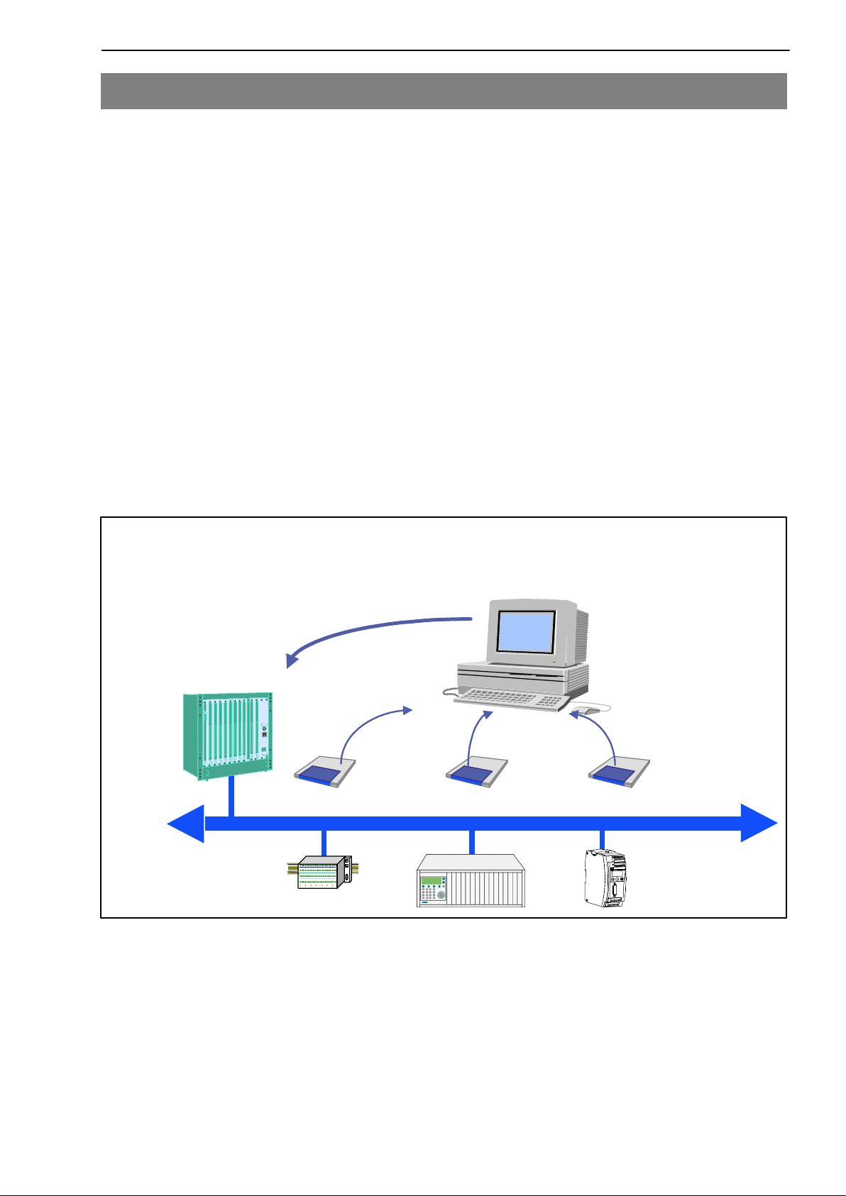
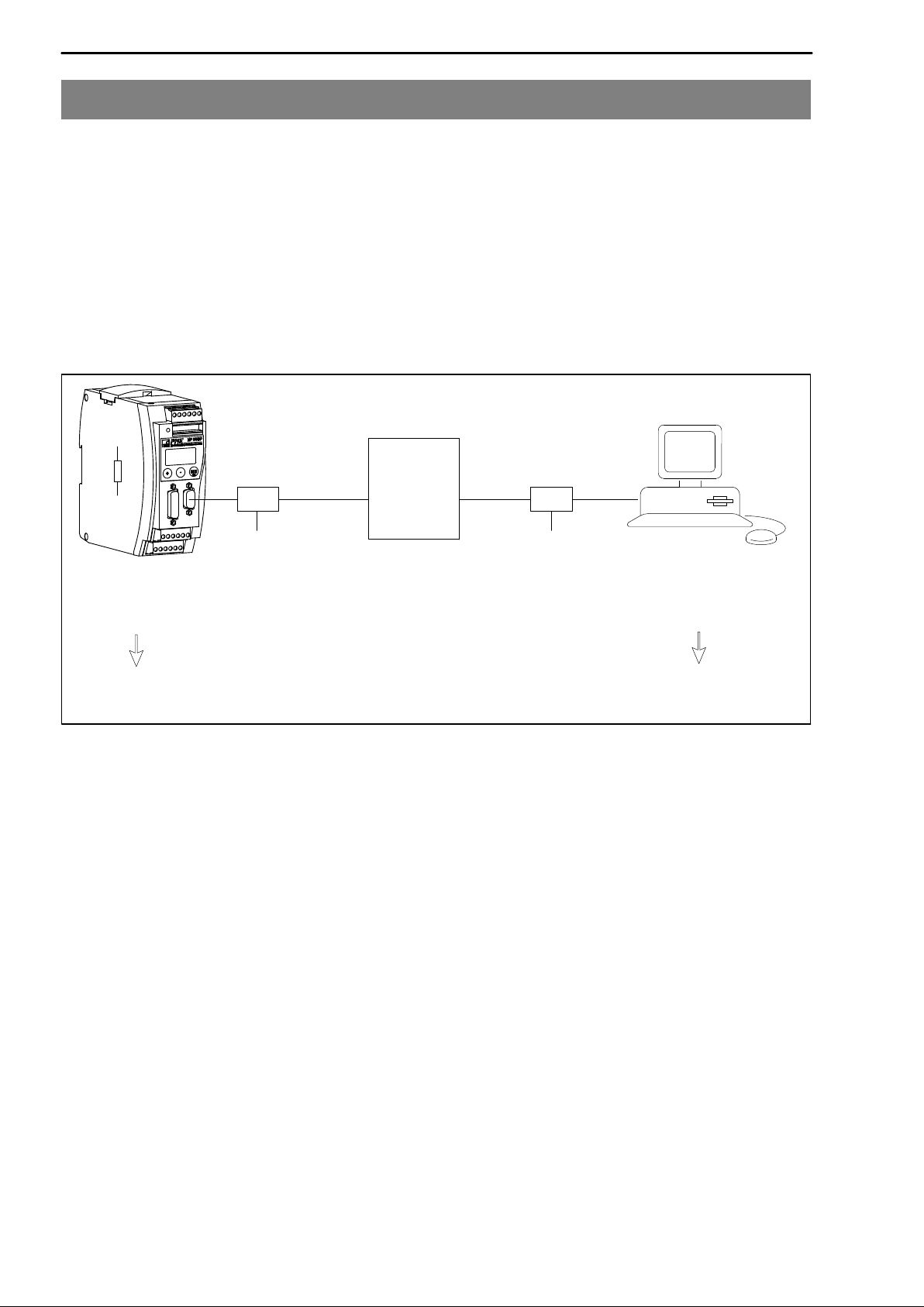
A GSE file describes the properties of a Profibus node in standardized form.
The configuration tool uses it to define which data held on individual bus
nodes will be exchanged on the Profibus.
5
A default GSE file for PME modules is supplied with the device (on system
CD: hbmxxx.gsd = German version; hbmxxxgse = English version).
Profibus
configurator
System configuration
PLC
Electronic device data sheets (GSE files)
GSE
PROFIBUS−DP
Fig. 2.1: Configuration with the aid of GSE files
HBMA0623-6.1 en/de/fr
Page 6
6
PME−MP60DP
2.1 Configuring and assigning parameters
• Start your configuration program (e.g. Step7; if you have no configuration
program, proceed to chapter 6.2)
• Load the HBM GSD file (PME system CD incl. GSD/GSE files for PME)
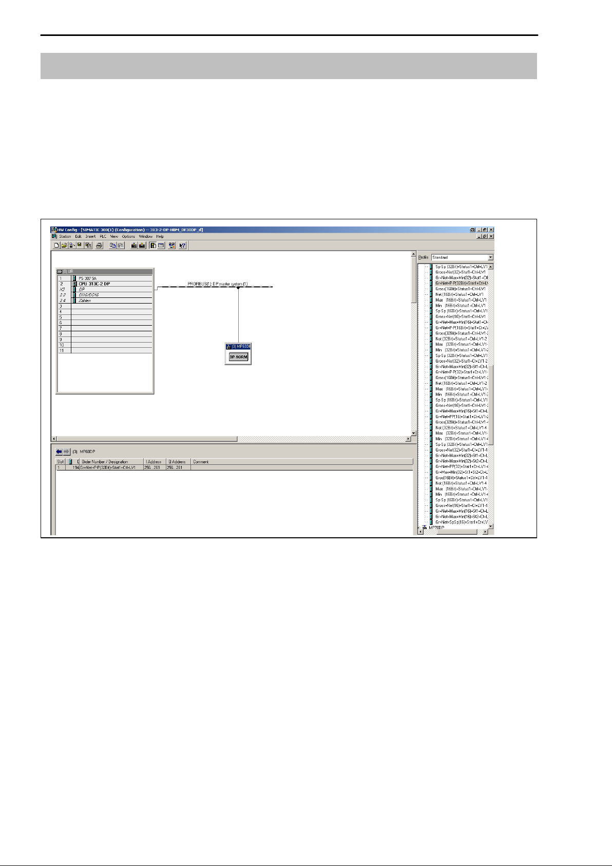
• Add an HBM device (Hardware catalog)
• From the hardware catalog choose the configuration you want on the
Profibus.
Fig. 2.2: Hardware configuration
HBM A0623-6.1 en/de/fr
Page 7
PME−MP60DP
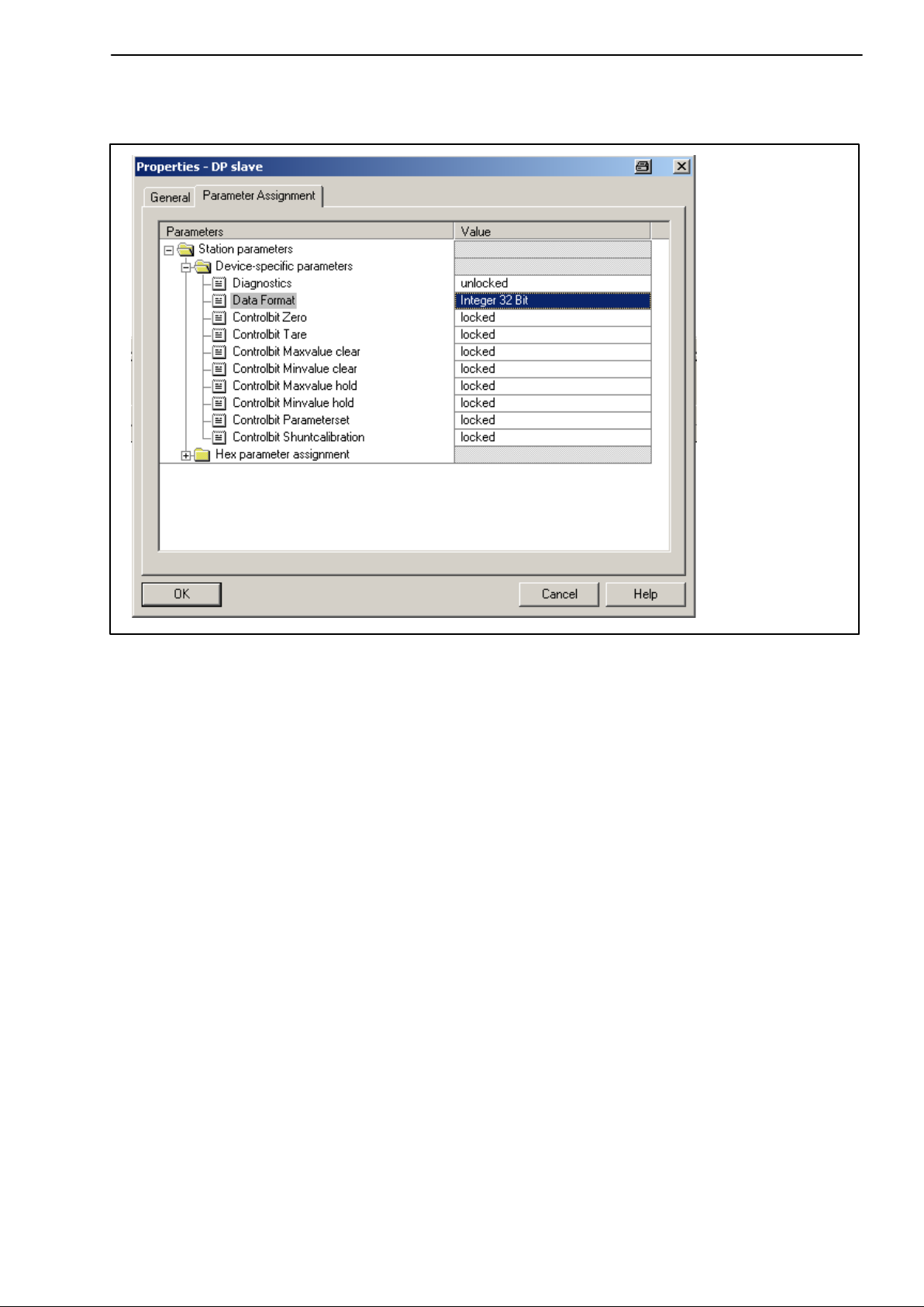
• Double-click on the configured entries to open the properties window and
select the required parameters.
7
Fig. 2.3: Setting parameters
Notes for users of the Simatic S7 PLC:
• To download consistent data of 3 bytes or over 4 bytes, use special
function modules SFC14 to read and SFC15 to write.
• In the case of the S7 3xx a maximum of 32 bytes of consistent data can be
downloaded.
To find out the meaning of the status bits and control word bits please refer to
the tables in chapter 6.3.
HBMA0623-6.1 en/de/fr
Page 8
8
PME−MP60DP
3 Installation
• Connect the MP60DP module to a 24 V supply voltage.
• Connect the Profibus cable to the MP60DP module. Ensure that a
terminating resistance is connected to the first and last Profibus unit (the
housing of the Profibus connector usually contains a sliding switch for this
purpose).
Example:
PLC
Profibus
connector
First device in
the bus line
sliding switch of Profibus connector to
”Resistance ON” .
Fig. 3.1: Profibus operation
Profibus
connector
Last device in
the bus line
sliding switch of Profibus
connector to ”Resistance ON”
HBM A0623-6.1 en/de/fr
Page 9
PME−MP60DP
4 Connections
Warning
Please note the safety instructions before commissioning the device.
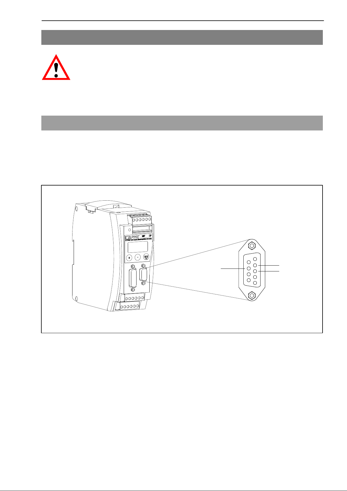
4.1 Pin assignment
For the pin assignment of the MP60DP module please refer to the Operating
Manual “PME industrial measurement electronics with MP60/MP07 module
field bus link”. On the front panel of the MP60DP is an additional 9−pin D-sub
connection socket for the Profibus connection.
9
6
0
9
RS485-A
Vcc (5V)
6
Fig. 4.1: Profibus connection in accordance with standard
Profibus
connection
socket
GND
5
RS485-RTS
1
RS485-B
HBMA0623-6.1 en/de/fr
Page 10
10
PME−MP60DP
5 Operation via the keyboard
−
During measurement you can press
the display (e.g. mV; V; Out,In; error messages).
Next to the status message “ERROR” the display shows the status of the
Profibus DP connection. One of the following status messages is displayed in
each case:
BD_SEAR (baud rate search)
WT_PARM (waiting for parameter)
WT_CONF (waiting for configuration)
DATA_EX (cyclical data communication)
ERROR (bus error)
+
− to view the status messages in
The LED shows the operating status (ready to take measurements, overflow
etc.) of the MP60DP. Instead of the CAN status (as with the MP60), however,
the Profibus status is displayed.
Operating status:
LED
colour
Green Steady light DATA_EX status
Yellow Steady light BD_SEAR, WT_PARM, WT_CONF status
Red Steady light ERROR status
Status Meaning
Profibus status
The representation of the other operating statuses is the same as that of the
MP60.
HBM A0623-6.1 en/de/fr
Page 11
PME−MP60DP
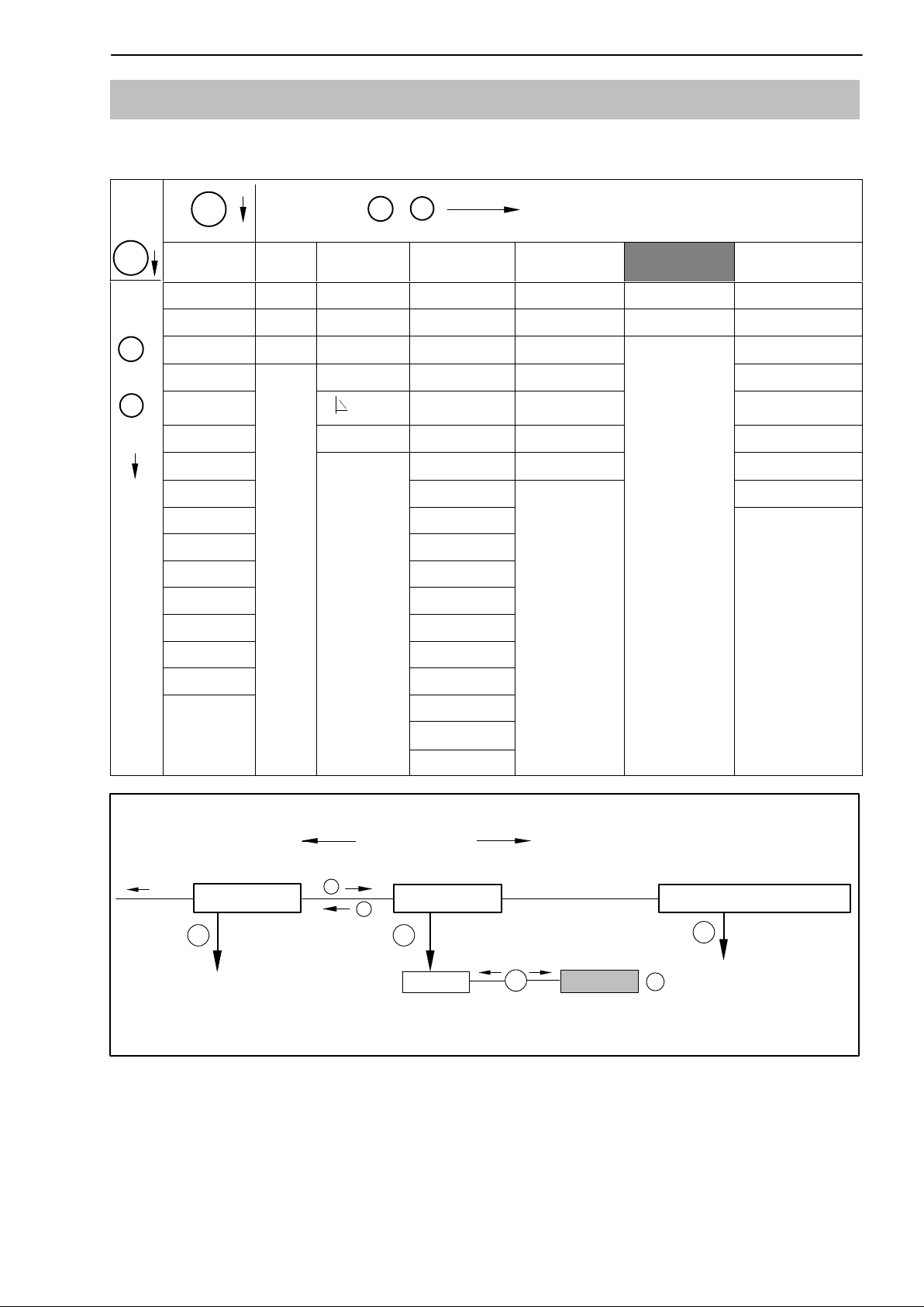
5.1 Expanded menus
New “Profibus” group in set-up mode:
−
SET
+
11
Groups
SET
+
Up
−
Down
DIALOGUE ... PEAK STORE IN/OUT CAN-BUS PROFIBUS
Password Operatn. Output1 Baud rate Address AmplType
PassStat InputMin ModeOut1 Address MAINGRP PrgVers
Language
I.DataS ClearPkV ModeOut2 Output
I.Displ.
I.Transd MAINGRP ModeOut3 PDO-Frmt SNo
I.Meas Output4
I.Condit ModeOut4 MAINGRP
I.Analog Zeroing
I.LimVal Tare
I.PStore PkMomMax
I.I/O PkHldMax
I.CAN PkMomMin
I.AddFnc PkHldMin
MAINGRP ParaCo1
InputMax
kN/s
1)
Output2 Profile >0<Rf kNm
Output3 OutR. ms Keyboard
MAINGRP
ADDITION
FUNCTION
HW synchr
HW vers.
1)
ParaCo2
Overview of parameters
InpFunc
MAINGRP
Groups
In/Out
CAN-bus
SET
+
PROFIBUS
−
SET
Address
Fig. 5.1: Setting up the Profibus address
SET
↑
↓
3 − 123
ADDITIONFUNCTION
SET
+/−
HBMA0623-6.1 en/de/fr
Page 12

12
PME−MP60DP
6 Setup for Profibus
6.1 Parameter assignment
The amplifier parameters are set via the keyboard or CAN−interface, as on
the MP60. The Profibus DP parameter assignment telegram defines some
parameters for the DP communication. If you use Profibus parameter
assignment tools which are able to evaluate the GSD files of GSD revision 1,
the following parameters are available for selection:
Parameter name Available
values
Diagnosis disabled
released
Data format integer 16 bits
integer 32 bits
floating point
Zeroing control bit disabled
released
Taring control bit disabled
released
Clear maximum
control bit
Clear minimum
control bit
Hold maximum
control bit
Hold minimum
control bit
disabled
released
disabled
released
disabled
released
disabled
released
Default Meaning
released release of external diagnosis
integer 16 bits defines the coding format for
measured values
disabled releases function for control of
output control word
disabled releases function for control of
output control word
disabled releases function for control of
output control word
disabled releases function for control of
output control word
disabled releases function for control of
output control word
disabled releases function for control of
output control word
Parameter set
control bit
disabled
released
disabled releases function for control of
output control word
Tab 6.1: Meaning of the parameters
The data format set applies to all the measured values exchanged in the
cyclical data communication. The definition of the decimal places for the
formats integer 16 bits and integer 32 bits is adopted from the module setting
(display, CAN−bus) (e.g. when 3 decimal places is specified, 2.0 mm is
communicated as integer value 2000). The choice of data format also affects
the length of the input data (integer 16 bits = 1 word per analogue value,
integer 32 bits and floating = 2 words per analogue value).
HBM A0623-6.1 en/de/fr
Page 13

PME−MP60DP
13
The targeted operation of the required control bits in the control word allows
you to secure all the functions not required against accidental operation in the
event of an error; otherwise, for example, the zero point set could be lost.
If you are using older parameter assignment tools the parameter values will
have to be converted to decimal or hexadecimal values:
Octet Bits Parameter name Available values Default Meaning
0 0..7 reserved 0 0 do not change
1)
1−2 all Diagnosis 0 = disabled
0xffff = released
3 all Data format 0 = integer 16 bits
1 = integer 32 bits
2 = floating point
5 0 Zeroing control
bit
5 1 Taring control bit 0 = disabled
5 4 Control bit
Delete maximum
5 5 Control bit
Delete minimum
5 6 Control bit
Hold maximum
0 = disabled
1 = released
1 = released
0 = disabled
1 = released
0 = disabled
1 = released
0 = disabled
1 = released
released release of external
diagnosis
integer 16 bits defines the coding
format for measured
values
disabled releases function for
control of output
control word
disabled releases function for
control of output
control word
disabled releases function for
control of output
control word
disabled releases function for
control of output
control word
disabled releases function for
control of output
control word
5 7 Control bit
Hold minimum
4 0−1 Parameter set
control bits
0 = disabled
1 = released
0 = disabled
3 = released
disabled releases function for
disabled releases function for
Tab 6.2: Contents of the parameter assignment message
1)
changed by your parameter assignment tool in certain circumstances
control of output
control word
control of output
control word
HBMA0623-6.1 en/de/fr
Page 14

14
PME−MP60DP
6.2 Configuration
The configuration defines which data content is exchanged in the cyclical data
communication. The following data is available for selection:
Input values:
Name Meaning Length
Gross gross measured value 1 or 2
words
Net net measured value (gross minus tare value) 1 or 2
words
Max contents of the maximum store 1 or 2
words
Min contents of the minimum store 1 or 2
words
Pk−Pk peak−to−peak, difference between max and min 1 or 2
words
Status1 status word with status of the limit switches and gen. error
bits
Status2 double status word with differentiated error flagging 2 words
1 word
Output values:
Name Meaning Length
Control word control word for triggering taring, zeroing, clearing the peak
value store, parameter set selection, etc.
Limit1 level at which limit switch 1 responds 1 or 2
Limit2 level at which limit switch 2 responds 1 or 2
Limit3 level at which limit switch 3 responds 1 or 2
Limit4 level at which limit switch 4 responds 1 or 2
1 word
words
words
words
words
The formats of the cyclically communicated data content are specified in detail
in chapter 6.3. The measured values are offered optionally as a 16-bit integer,
32-bit integer or 32 bit float. The values are always scaled to physical size
with the number of decimal places of your choice. Information on whether the
16 bit format or a 32 bit format is used and on the number of decimal places is
defined in the parameter assignment message.
Typical combinations are predefined in the GSD file. If you require other
combinations you can expand the GSD file accordingly using the following
specifications.
HBM A0623-6.1 en/de/fr
Page 15

PME−MP60DP
15
6.2.1 Defining your own configuration combinations
Only one configuration entry is available. The special identification format
(special format) must be used for this. The manufacturer−specific data
specifies the contents and thus also the length of the input data and is 2 bytes
in length.
CFG entry no. Meaning Contents
0 channel 1 special format with inputs and outputs, maximum 9 words
output, maximum 13 words input, 2 bytes comment length
(data)
The following input and output data can be configured for the cyclical data
communication. The choice of which data is actually transferred is
communicated via the manufacturer−specific data of the special identification
format.
Configuration
manufacturer−
specific data
Byte no. Bit no. (words) (words)
0 0 1(2) Gross
0 1 1(2) Net
0 2 1(2) Max
0 3 1(2) Min
0 4 1(2) Peak−to−peak
0 5 1 Status1
0 6 2 Status2
1 0 1 Control word
1 1 1(2) Limit value level 1
1 2 1(2) Limit value level 2
1 3 1(2) Limit value level 3
Length of cyclical data
inputs
Length of cyclical data
outputs
Contents of cyclical
data
Input values:
Output values:
1 4 1(2) Limit value level 4
Tab 6.3: Selecting the data content via the manufacturer−specific data
The length of the input data is the sum of all the data lengths selected for the
communication in words. When selecting the 32 bit format and the float format
for measured values, the length values in brackets must be used.
HBMA0623-6.1 en/de/fr
Page 16

16
p
(
PME−MP60DP
The configuration telegram thus has the following format:
CFG byte Meaning Permitted values for CFG (hex.)
1 header 0xC2 (inputs and outputs, 2 bytes manufacturer−specific
data)
2 length of outputs 0x40 − 0x48 (1 to 9 words of outputs) or
0xC0 − 0xC8 (1 to 9 words of outputs with consistency)
3 length of inputs 0xC0 − 0xCC or
0x40 − 0x7C (1 to 13 words of inputs with/without
consistency)
4
5
Tab 6.4: Contents of the configuration telegram
user−specific data
Input data
Output data
selection of the data content (see
Tab 6.3)
When using the 32 bit formats data consistency must always be set.
6.3 Cyclical data exchange
Depending on the configuration, the following data content is exchanged:
6.3.1 Inputs (from MP55IBS to the PLC) Measured values
Measured values can be communicated in various forms of representation.
The forms of representation available for selection are floating (2 words, 32
bit), 16 bit fixed point number (1 word, 16 bit integer in two’s complement,
decimal place must be known to the reader) or 32 bit fixed point number (2
words, 32 bit integer in two’s complement, decimal place must be known to
the reader). For conversion of the values to fixed point representation the
number of decimal places in the module parameter assignment (display,
CAN−bus) is used as a basis.
HBM A0623-6.1 en/de/fr
Page 17
PME−MP60DP
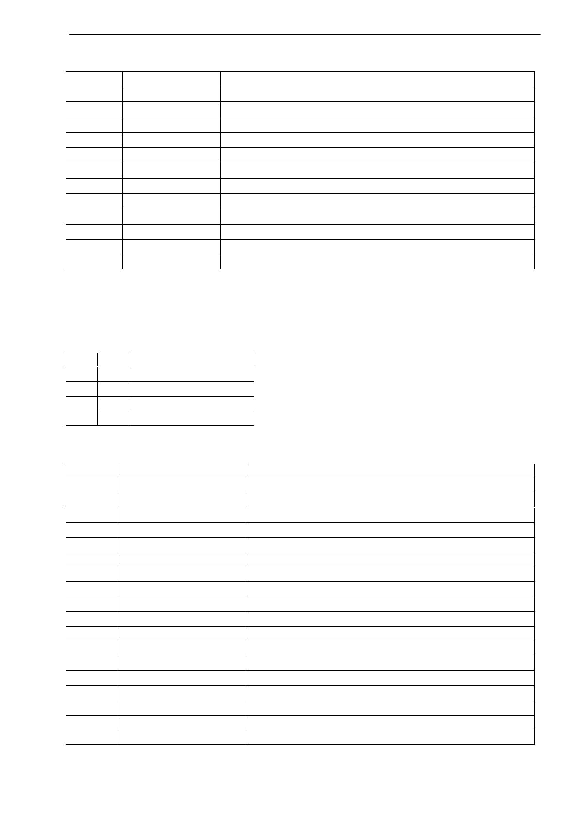
Status 1
Bits Name Meaning
0 Ovfl measured values overflow
1 AOutOvfl analogue output overflow
2 ScalErr scaling defective
3 EEPROMErr EEPROM (parameter set) defective
4 Limit1 status of limit switch 1
5 Limit2 status of limit switch 2
6 Limit3 status of limit switch 3
7 Limit4 status of limit switch 4
8 PAR1 active parameter set bit 1
9 PAR2 active parameter set bit 1
10..14 res reserved
15 MViO Measured value in order 1) (if bit 0,2,3=0)
Tab 6.5: Contents of status 1
1)
Meaning of MViO:
NOR operation of: MesswOvfl, SkalErr, EEPROMErr.
MesswOvfl is the OR operation of ADCOvfl, HardwOvfl, GrossOvfl, NetOvfl
17
The parameter set number is coded in 2 bit binary:
Bit 8 Bit 9 Parameter set no.
0 0 1
1 0 2
0 1 3
1 1 4
Status 2
Double status word 2 returns detailed error flagging.
Bits Name Meaning
0 HardwOvfl hardware overflow
1 ADCOvfl ADC overflow
2 GrossOvfl gross signal overflow
3 NetOvfl net signal overflow
4 AOutOvfl analogue output overflow
5 MaxOvfl maximum overflow
6 MinOvfl minimum overflow
7 NegOvfl overflow in negative direction
8 Limit1 status of limit switch 1
9 Limit2 status of limit switch 2
10 Limit3 status of limit switch 3
11 Limit4 status of limit switch 4
12 ScalInError scaling input invalid
13 ScalOutError scaling output invalid
14 GainError nominal value exceeded
15 InitError works calibration defective
16 TransducerError transducer error
17..31 res reserved
Tab 6.6: Contents of status 2
HBMA0623-6.1 en/de/fr
Page 18

18
PME−MP60DP
6.3.2 Outputs (from the PLC to MP55IBS) Limit values
Limit values are displayed in the same format as the measured values (16 bit
integer, 32 bit integer or floating format). The operating direction and
hysteresis remain unchanged and are set via the operating panel or the
CAN−bus.
Control word
Bits Name Meaning
0 ZERO 0−1 autom. triggers zeroing
1 TAR 0−1 triggers taring
2 SHUNT SHUNT ON / OFF
3 res reserved
4 CLRMAX 0−1 clears the MAX peak value store
5 CLRMIN 0−1 clears the MIN peak value store
6 HOLDMAX 1: freeze MAX peak value store
7 HOLDMIN 1: freeze MIN peak value store
8 PAR1 parameter set selection bit 1
9 PAR2 parameter set selection bit 2
10..15 res reserved
Tab 6.7: Contents of control word
HBM A0623-6.1 en/de/fr
Page 19

PME−MP60DP
19
6.4 Diagnosis
The MP60DP module makes a device diagnosis available as an external
diagnosis which can be released via the parameter assignment diagram.
The external diagnosis is 4 bytes long. The first byte contains the identification
character for the version number. The second byte contains the identification
character for device diagnosis. In the third and fourth bytes one bit each is
reserved for various fault causes.
Octet Bits Value Meaning
0 0..7 c1 version 1
1 0..7 4 length of device diagnosis is 4 bytes in total
2 0 0
1
2 1 ADC overflow
2 2 0
1
2 3 0
1
2 4 0
1
2 5 0
1
2 6 0
1
2 7 res
3 0..3 res
3 4 0
1
3 5 0
1
scaling of input characteristics defective
scaling of output characteristics defective
hardware overflow
gross overflow
net overflow
analogue output overflow
maximum overflow
minimum overflow
3 6 0
1
3 7 0
1
4 0 0
1
4 1...7 res
nominal value exceeded
works calibration defective
transducer error
Tab 6.8: Contents of diagnosis
HBMA0623-6.1 en/de/fr
Page 20

20
PME−MP60DP
HBM A0623-6.1 en/de/fr
Page 21

PME−MP60DP
21
Inhalt Seite
1 Einführung 22 . . . . . . . . . . . . . . . . . . . . . . . . . . . . . . . . . . . . . . . . . . . . . . . . . .
2 Leitfaden für den Anschluss an SPS 23 . . . . . . . . . . . . . . . . . . . . . . . . . .
2.1 Konfigurieren und Parametrieren 24 . . . . . . . . . . . . . . . . . . . . . . . . . . . .
3 Installieren 26 . . . . . . . . . . . . . . . . . . . . . . . . . . . . . . . . . . . . . . . . . . . . . . . . . .
4 Anschließen 27 . . . . . . . . . . . . . . . . . . . . . . . . . . . . . . . . . . . . . . . . . . . . . . . . .
4.1 Anschlussbelegung 27 . . . . . . . . . . . . . . . . . . . . . . . . . . . . . . . . . . . . . . .
5 Bedienen über Tastatur 28 . . . . . . . . . . . . . . . . . . . . . . . . . . . . . . . . . . . . . .
5.1 Erweiterte Menüs 29 . . . . . . . . . . . . . . . . . . . . . . . . . . . . . . . . . . . . . . . . .
6 Einstellungen für Profibus 30 . . . . . . . . . . . . . . . . . . . . . . . . . . . . . . . . . . . .
6.1 Parametrierung 30 . . . . . . . . . . . . . . . . . . . . . . . . . . . . . . . . . . . . . . . . . . .
6.2 Konfiguration 32 . . . . . . . . . . . . . . . . . . . . . . . . . . . . . . . . . . . . . . . . . . . . .
6.2.1 Definition eigener Konfigurations-Kombinationen 33 . . . . . . . .
6.3 Zyklischer Datenaustausch 34 . . . . . . . . . . . . . . . . . . . . . . . . . . . . . . . . .
6.3.2 Ausgänge (von der SPS an den MP60DP gesendet) 35 . . . . .
6.4 Diagnose 36 . . . . . . . . . . . . . . . . . . . . . . . . . . . . . . . . . . . . . . . . . . . . . . . .
HBMA0623-6.1 en/de/fr
Page 22

22
PME−MP60DP
1 Einführung
In dieser Bedienungsanleitung werden nur diejenigen Funktionen beschrieben, die vom MP60 abweichen. Die Funktionalität des MP60DP entspricht der
des MP60.
Das Frequenz-Messmodul MP60DP ist um eine Profibus-Schnittstelle ergänzt
worden. Die Funktionalität auf der CAN-Schnittstelle bleibt erhalten; das Objektverzeichnis wird um einige Parameter der Profibus-Kopplung erweitert.
Der Profibus-Anschluss erfolgt über einen 9poligen Sub-D-Steckanschluss
(Normkonform) auf der Front neben dem Aufnehmeranschlussstecker.
Auf dem Profibus wird das Protokoll DP verwendet.
Übertragen werden:
− die Messwerte (Brutto, Netto, Spitzenwerte)
− der Zustand der Grenzwertschalter
− Steuerbits für Tarieren, Nullstellen, Spitzenwertspeichersteuerung, Parame-
tersatzumschaltung und
− optional die Grenzwertpegel
HBM A0623-6.1 en/de/fr
Page 23

PME−MP60DP
23
2 Leitfaden für den Anschluss an SPS
Die Schritte zur erfolgreichen Anbindung an den Profibus:
1. Mechanischer Anschluss des Gerätes an den Profibus (siehe Seite 26 und
Seite 27).
2. Parameter am Gerät einstellen, siehe Seite 30 (kann auch mit der HBMSoftware “PME-Assistent” erfolgen).
3. Konfiguration und Parametrierung des Profibus-Telegrammes mit einem
Konfigurationswerkzeug (z.B. Step7) und GSD-Dateien oder manuell nach
Kapitel 6.2.
Eine GSD-Datei beschreibt die Eigenschaften eines Profibus-Teilnehmers in
standardisierter Form. Sie wird vom Konfigurationswerkzeug dazu benutzt,
festzulegen, welche Dateninhalte der einzelnen Busteilnehmer auf dem Profibus ausgetauscht werden.
Eine Standard-GSD (hbmxxx.gsd = deutsch; hbmxxxgse = englisch) für PMEModule wird mit dem Gerät (System-CD) ausgeliefert.
Profibus
Konfigurator
Systemkonfiguration
SPS
Elektronische Gerätedatenblätter (GSD-Dateien)
GSD
PROFIBUS−DP
Abb. 2.4: Konfiguration mit GSD-Dateien
HBMA0623-6.1 en/de/fr
Page 24

24
PME−MP60DP
2.1 Konfigurieren und Parametrieren
• Starten Sie Ihr Konfigurationsprogramm (z.B. Step7; besitzen Sie kein Konfigurationsprogramm, verfahren Sie nach Kapitel 6.2).
• Laden Sie die HBM-GSD-Datei (PME-System-CD).
• Fügen Sie ein HBM-Gerät hinzu (Hardwarekatalog).
• Wählen Sie aus dem Hardwarekatalog die Konfiguration, die Sie auf dem
Profibus benötigen.
Abb. 2.5: Hardware-Konfiguration
HBM A0623-6.1 en/de/fr
Page 25

PME−MP60DP
• Öffnen Sie durch Doppelklicken der konfigurierten Einträge das Eigenschaftsfenster und wählen Sie die gewünschten Parameter aus.
25
Abb. 2.6: Parameter einstellen
Hinweise für Nutzer der SPS Simatic S7:
• Zum Übertragen konsistenter Daten von 3 Byte oder über 4 Byte müssen
Sie den Sonderfunktionsbaustein SFC14 zum Lesen und SFC15 zum
Schreiben benutzen.
• Bei der S7 3xx können maximal 32 Byte konsistente Daten übertragen werden.
Die Bedeutung der Bits von Status und Steuerwort entnehmen Sie den
Tabellen in Kapitel 6.3.
HBMA0623-6.1 en/de/fr
Page 26

26
PME−MP60DP
3 Installieren
• Modul MP60DP an 24 V Versorgungsspannung anschließen und über die
Tastatur oder das Setup-Programm die gewünschte Profibus-Adresse einstellen.
• Schließen Sie die Profibus-Leitung an das Modul MP60DP an. Achten Sie
darauf, dass am ersten und letzten Profibus-Teilnehmer ein Abschlusswiderstand von zugeschaltet ist (am Gehäuse des Profibus-Steckers befindet sich hierzu üblicherweise ein Schiebeschalter).
Beispiel:
SPS
Profibus-Stecker Profibus-Stecker
Erstes Gerät in
der Busleitung
Schiebeschalter des Profibus-Steckers auf
“Widerstand EIN”
Abb. 3.2: Profibus-Betrieb
Letztes Gerät in
der Busleitung
Schiebeschalter des ProfibusSteckers auf “Widerstand EIN”
HBM A0623-6.1 en/de/fr
Page 27

PME−MP60DP
27
4 Anschließen
WARNUNG
Beachten Sie vor der Inbetriebnahme des Gerätes die
Sicherheitshinweise.
4.1 Anschlussbelegung
Die Anschlussbelegungen des Moduls MP60DP entnehmen Sie bitte der Bedienungsanleitung “Industrielle Messelektronik PME mit Feldbusanbindung
Modul MP60/MP07”. Auf der Frontseite des MP60DP befindet sich eine zusätzliche 9polige D-Sub-Anschlussbuchse für den Profibus-Anschluss.
6
0
Abb. 4.2: Profibus-Anschluss nach Norm
RS485-A
Vcc (5V)
9
6
Profibus-
Anschluss-
buchse
GND
5
RS485-RTS
1
RS485-B
HBMA0623-6.1 en/de/fr
Page 28

28
PME−MP60DP
5 Bedienen über Tastatur
−
Während des Messens können Sie sich − durch Drücken von
Display die Statusmeldungen ansehen (z.B. mV; V; Ausg,Eing; Fehlermeldungen).
Im Anschluss an die Statusmeldung “FEHLER” zeigt das Display den Status
der Profibus-DP-Verbindung. Jeweils eine der folgenden Statusmeldungen
wird dargestellt:
BD_SEAR (Baudratensuche)
WT_PARM (Warten auf Parameter)
WT_CONF (Warten auf Konfiguration)
DATA_EX (Zyklischer Datenverkehr)
+
− im
ERROR (Bus-Fehler)
Die LED zeigt die Betriebszustände (Messbereit, Overflow etc.) des MP60DP
an. Statt des CAN-Zustandes (wie beim MP60) wird jedoch der ProfibusZustand angezeigt.
Betriebszustand:
LED-Farbe Zustand Bedeutung
Profibus-Zustand
Grün Leuchtet stetig Zustand DATA_EX
Gelb Leuchtet stetig Zustände BD_SEAR, WT_PARM, WT_CONF
Rot Leuchtet stetig Zustand ERROR
Die Darstellung der anderen Betriebszustände entspricht denen des MP60.
HBM A0623-6.1 en/de/fr
Page 29

PME−MP60DP
HPTGRP
HPTGRP
5.1 Erweiterte Menüs
Neue Gruppe “Profibus” im Einstellbetrieb:
−
SET
+
29
Gruppen
SET
+
Up
−
Down
DIALOG ... SPITZWRT EIN/AUSG CAN-BUS PROFIBUS ZUSATZFUNKTION
Passwort Freigabe Ausgang1 Baudrate Adresse Verst Typ
PassStat Eing.Min Mode Aus1 Adresse HPTGRP PrgVers
Sprache
E.ParaS SpLöschn Mode Aus2 Ausgabe HW Synchr
E.Anzeig
E.Aufneh
E.Einmes Ausgang4
E.Aufber Mode Aus4 HPTGRP
E.Analog Nullst.
E.Grnzw Tarier.
E.Spitzw SpMomMax
E.E/A SpHltMax
E.CAN SpMomMin
E.Zusatz SpHltMin
HPTGRP ParaCod1
Eing.Max
kN/s
HPTGRP
1)
Ausgang2 Profil >0<Rf kNm
Ausgang3 AusgR. ms Tastatur
Mode Aus3 PDO-Frmt SNr
HW-Vers.
ParaCod2
1)
Übersicht der Parameter
EingFkt.
Gruppen
Ein/Ausg
CAN-Bus
SET
Abb. 5.2: Profibus-Adresse einstellen
+
PROFIBUS
−
SET
Adresse
SET
↑
↓
3 − 123
ZUSATZ-FUNKTION
SET
+/−
HBMA0623-6.1 en/de/fr
Page 30

30
PME−MP60DP
6 Einstellungen für Profibus
6.1 Parametrierung
Die Verstärkerparameter werden wie beim MP60DP über Tastatur oder CANSchnittstelle eingestellt. Das Profibus-DP-Parametriertelegramm legt einige
Parameter für die DP-Übertragung fest. Wenn Sie Profibus-Parametriertools
verwenden, die GSD-Files der GSD-Revision 1 verwerten können, stehen
folgende Parameter zur Auswahl:
Parameter-Name mögliche
Werte
Diagnose gesperrt
freigegeben
Datenformat Integer 16 Bit
Integer 32 Bit
Floating Point
Steuerbit Null-
stellen
Steuerbit Tarieren gesperrt
Steuerbit Maximum
löschen
Steuerbit Minimum
löschen
Steuerbit Maximum
halten
Steuerbit Minimum
halten
gesperrt
freigegeben
freigegeben
gesperrt
freigegeben
gesperrt
freigegeben
gesperrt
freigegeben
gesperrt
freigegeben
Default Bedeutung
freigegeben Freigabe der externen Diagnose
Integer 16 Bit Festlegung des Kodierungsfor-
mats für Messwerte
gesperrt gibt Funktion für Steuerung über
Ausgangssteuerwort frei
gesperrt gibt Funktion für Steuerung über
Ausgangssteuerwort frei
gesperrt gibt Funktion für Steuerung über
Ausgangssteuerwort frei
gesperrt gibt Funktion für Steuerung über
Ausgangssteuerwort frei
gesperrt gibt Funktion für Steuerung über
Ausgangssteuerwort frei
gesperrt gibt Funktion für Steuerung über
Ausgangssteuerwort frei
Steuerbit Parame-
tersatz
gesperrt
freigegeben
gesperrt gibt Funktion für Steuerung über
Ausgangssteuerwort frei
Tab. 6.1. Bedeutung der Parameter
Das eingestellte Datenformat gilt für alle im zyklischen Datenverkehr ausgetauschten Messwerte. Die Angabe der Nachkommastellen für die Formate Integer 16 Bit und Integer 32 Bit wird aus der Modul-Einstellung (Display, CANBus) übernommen (z.B. 2.0 mm wird bei Vorgabe von 3 Nachkommastellen
als Integer-Wert 2000 übertragen). Die Wahl des Datenformats hat auch Auswirkungen auf die Länge der Eingangsdaten (Integer 16 Bit = 1 Wort pro Analogwert, Integer 32 Bit und Float = 2 Worte pro Analogwert).
HBM A0623-6.1 en/de/fr
Page 31

PME−MP60DP
31
Die gezielte Freigabe der benötigten Steuerbits im Steuerwort bietet die Möglichkeit, alle nicht benötigten Funktionen im Fehlerfall gegen eine ungewollte
Auslösung abzusichern, da sonst z.B. der einmal eingestellte Nullpunkt verloren gehen könnte.
Falls Sie ältere Parametriertools einsetzen, müssen die Parameterwerte in
Dezimal- oder Hexadezimalwerte umgerechnet werden:
Octet Bit Parameter-Name mögliche Werte Default Bedeutung
0 0..7 reserviert 0 0 nicht verändern
1)
1−2 alle Diagnose 0 = gesperrt
0xffff = freigegeben
3 alle Datenformat 0 = Integer 16 Bit
1 = Integer 32 Bit
2 = Floating Point
5 0 Steuerbit
Nullstellen
5 1 Steuerbit
Tarieren
5 4 Steuerbit
Maximum
löschen
5 5 Steuerbit
Minimum
löschen
5 6 Steuerbit
Maximum halten
0 = gesperrt
1 = freigegeben
0 = gesperrt
1 = freigegeben
0 = gesperrt
1 = freigegeben
0 = gesperrt
1 = freigegeben
0 = gesperrt
1 = freigegeben
freigegeben Freigabe der exter-
nen Diagnose
Integer 16 Bit Festlegung des Ko-
dierungsformats für
Messwerte
gesperrt gibt Funktion für
Steuerung über Aus-
gangssteuerwort frei
gesperrt gibt Funktion für
Steuerung über Aus-
gangssteuerwort frei
gesperrt gibt Funktion für
Steuerung über Aus-
gangssteuerwort frei
gesperrt gibt Funktion für
Steuerung über Aus-
gangssteuerwort frei
gesperrt gibt Funktion für
Steuerung über Aus-
gangssteuerwort frei
5 7 Steuerbit
Minimum halten
5 0−1 Steuerbits
Parametersatz
0 = gesperrt
1 = freigegeben
0 = gesperrt
3 = freigegeben
Tab. 6.2. Inhalt des Parametrier-Telegramms
1)
wird u.U. von Ihrem Parametriertool sebständig verändert
gesperrt gibt Funktion für
Steuerung über Aus-
gangssteuerwort frei
gesperrt gibt Funktion für
Steuerung über Aus-
gangssteuerwort frei
HBMA0623-6.1 en/de/fr
Page 32

32
PME−MP60DP
6.2 Konfiguration
Die Konfiguration legt fest, welche Dateninhalte im zyklischen Datenverkehr
ausgetauscht werden. Für die Auswahl stehen folgende Daten zur Verfügung:
Eingangswerte:
Bezeichnung Bedeutung Länge
Brutto Brutto-Messwert 1 oder 2
Worte
Netto Netto-Messwert (Brutto abzüglich Tara-Wert) 1 oder 2
Worte
Max Inhalt des Maximum-Speichers 1 oder 2
Worte
Min Inhalt des Minimum-Speichers 1 oder 2
Worte
Sp−Sp Spitze-Spitze, Differenz zwischen Max und Min 1 oder 2
Worte
Status1 Statuswort mit Zustand der Grenzwertschalter u. allg. Fehler-
bits
Status2 Status-Doppelwort mit differenzierter Fehlerkennzeichnung 2 Worte
1 Wort
Ausgangswerte:
Bezeichnung Bedeutung Länge
Steuerwort Steuerwort zur Auslösung von Tarierung, Nullstellen, löschen
der Spitzenwertspeicher, Parametersatzauswahl etc.
GW1 Pegel, bei dem Grenzwertschalter 1 anspricht 1 oder 2
GW2 Pegel, bei dem Grenzwertschalter 2 anspricht 1 oder 2
GW3 Pegel, bei dem Grenzwertschalter 3 anspricht 1 oder 2
GW4 Pegel, bei dem Grenzwertschalter 4 anspricht 1 oder 2
1 Wort
Worte
Worte
Worte
Worte
Die Formate der zyklisch übertragenen Dateninhalte werden im Detail im
Kapitel 6.3 angegeben. Die Messwerte werden wahlweise als 16-Bit Integer,
32-Bit Integer oder 32 Bit Float angeboten. Die Werte sind immer auf physikalische Größe skaliert mit wählbarer Nachkommastellenzahl. Die Angaben, ob
das 16 Bit oder ein 32 Bit-Format verwendet wird, sowie die Anzahl der Nachkommastellen wird im Parametrier-Telegramm festgelegt.
Im GSD-File sind typische Kombinationen vordefiniert. Wenn Sie andere
Kombinationen benötigen, können Sie anhand der folgenden Spezifikationen
das GSD-File entsprechend erweitern.
HBM A0623-6.1 en/de/fr
Page 33

PME−MP60DP
33
6.2.1 Definition eigener Konfigurations-Kombinationen
Es steht nur ein Konfigurations-Eintrag zur Verfügung. Bei diesem muss das
spezielle Kennungsformat (Spezialformat) verwendet werden. Die herstellerspezifischen Daten spezifizieren die Inhalte und damit auch die Länge der
Eingabedaten und haben eine Länge von 2 Byte.
CFG-Eintrag
Nr.
0 Kanal 1 Spezialformat mit Ein- und Ausgabe, maximal 9 Worte Aus-
Bedeutung Inhalt
gabe, maximal 13 Worte Eingabe, 2 Byte Kommentarlänge
(Daten)
Folgende Ein- und Ausgangsdaten können für den zyklischen Datenverkehr
konfiguriert werden. Die Auswahl, welche Daten tatsächlich übertragen werden, wird über die herstellerspezifischen Daten des speziellen Kennungsformats mitgeteilt.
Konfiguration
herstellerspez.
Daten
Byte-Nr. Bit-Nr. (Worte) (Worte)
0 0 1(2) Brutto
0 1 1(2) Netto
Länge zyklische Daten
Eingänge
Länge zyklische Daten
Ausgänge
Inhalt zyklische Daten
Eingangswerte:
0 2 1(2) Max
0 3 1(2) Min
0 4 1(2) Spitze-Spitze
0 5 1 Status1
0 6 2 Status2
Ausgangswerte:
1 0 1 Steuerwort
1 1 1(2) Grenzwertpegel 1
1 2 1(2) Grenzwertpegel 2
1 3 1(2) Grenzwertpegel 3
1 4 1(2) Grenzwertpegel 4
Tab. 6.3. Auswahl der Dateninhalte über die herstellerspezifischen Daten
Die Länge der Eingangsdaten ergibt sich als Summe aller für die Übertragung
ausgewählter Datenlängen in Worten. Bei Auswahl des 32-Bit Formats sowie
des Float-Formats für Messwerte müssen die Längenwerte in Klammern verwendet werden.
HBMA0623-6.1 en/de/fr
Page 34

34
p
(
Das Konfigurationstelegramm hat damit folgendes Format:
PME−MP60DP
CFG-
Byte
1 Kopf 0xC2 (Ein- und Ausgaben, 2 Byte herstellerspez. Daten)
2 Länge Ausgaben 0x40...0x48 (1 bis 9 Worte Ausgaben) oder
3 Länge Eingaben 0xC0 ... 0xCC oder
4
5
Bedeutung Erlaubte Werte für CFG (Hex)
0xC0...0xC8 (1 bis 9 Worte Ausgaben mit Konsistenz)
0x40..0x7C (1 bis 13 Worte Eingaben mit / ohne Konsi-
stenz)
benutzerspezifische
Daten
Eingangsdaten
Ausgangsdaten
Auswahl der Dateninhalte (siehe
Tab. 6.3.)
Tab. 6.4. Inhalt des Konfigurationstelegramms
Bei Verwendung der 32-Bit-Formate ist unbedingt Datenkonsistenz einzustellen.
6.3 Zyklischer Datenaustausch
Abhängig von der Konfiguration werden folgende Dateninhalte ausgetauscht:
6.3.1 Eingänge (vom MP60DP an die SPS geliefert)
Messwerte
Messwerte können in unterschiedlicher Darstellung übertragen werden. Zur
Auswahl stehen Float (2 Worte, 32Bit), 16 Bit Festpunktzahl (1 Wort, 16 Bit Integer im Zweierkomplement, Kommastelle muss der lesenden Stelle bekannt
sein) oder 32 Bit Festpunktzahl (2 Worte, 32 Bit Integer im Zweierkomplement, Kommastelle muss der lesenden Stelle bekannt sein). Für die Umrechnung der Werte in die Festpunktdarstellung wird die Anzahl der Nachkommastellen in der Modulparametrierung (Display, CAN-Bus) zugrundegelegt.
Status 1
Bit Name Bedeutung
0 MesswOvfl Messwerte übersteuert
1 AOutOvfl Analogausgang übersteuert
2 SkalErr Skalierung fehlerhaft
3 EEPROMErr EEPROM (Parametersatz) fehlerhaft
4 GW1 Zustand Grenzwertschalter 1
5 GW2 Zustand Grenzwertschalter 2
6 GW3 Zustand Grenzwertschalter 3
7 GW4 Zustand Grenzwertschalter 4
8 PAR1 aktiver Parametersatz-Bit 1
9 PAR2 aktiver Parametersatz-Bit 2
10..14 res reserviert
15 MWiO Messwert in Ordnung1) (wenn Bit 0,2,3=0)
Tab. 6.5. Inhalt Status 1
1)
Bedeutung von MWiO:
Negierte ODER-Verknüpfung von: MesswOvfl, SkalErr, EEPROMErr.
MesswOvfl ist die Oder-Verknüpfung von ADCOvfl, HardwOvfl, GrossOvfl, NetOvfl
HBM A0623-6.1 en/de/fr
Page 35

PME−MP60DP
Die Parametersatznummer ist in 2 Bit binär kodiert:
Bit 8 Bit 9 Parametersatz-Nr
0 0 1
1 0 2
0 1 3
1 1 4
Status 2
Das Status-Doppelwort 2 liefert eine detailliertere Fehlerkennzeichung.
Bit Name Bedeutung
0 HardwOvfl Übersteuerung Hardware
1 ADCOvfl ADC übersteuert
2 GrossOvfl Bruttosignal übersteuert
3 NetOvfl Nettosignal übersteuert
35
4 AOutOvfl Analogausgang übersteuert
5 MaxOvfl Maximum übersteuert
6 MinOvfl Minimum übersteuert
7 NegOvfl Übersteuerung in negative Richtung
8 GW1 Zustand Grenzwertschalter 1
9 GW2 Zustand Grenzwertschalter 2
10 GW3 Zustand Grenzwertschalter 3
11 GW4 Zustand Grenzwertschalter 4
12 SkalInError Skalierung Eingang ungültig
13 SkalOutError Skalierung Ausgang ungültig
14 GainError Nennwert überschritten
15 UrcalError Werkskalibrierung fehlerhaft
16 TransducerError Aufnehmerfehler
17..31 res reserviert
Tab. 6.6. Inhalt Status 2
6.3.2 Ausgänge (von der SPS an den MP60DP gesendet) Grenzwerte
Grenzwertpegel werden im selben Format wie die Messwerte dargestellt (16
Bit Integer, 32 Bit Integer oder Float-Format). Die Schaltrichtung und Hysterese bleiben unverändert und werden über das Bedienfeld oder den CAN-Bus
eingestellt.
HBMA0623-6.1 en/de/fr
Page 36

36
Steuerwort
Bit Name Bedeutung
0 NULL 0−1 löst autom. Nullstellen aus
1 TAR 0−1 löst Tarierung aus
2 SHUNT Shunt EIN / AUS
3 res reserviert
4 CLRMAX 0−1 löscht den Spitzenwertspeicher MAX
5 CLRMIN 0−1 löscht den Spitzenwertspeicher MIN
6 HOLDMAX 1: Spitzenwertspeicher MAX einfrieren
7 HOLDMIN 1: Spitzenwertspeicher MIN einfrieren
8 PAR1 Parametersatz-Auswahl Bit 1
9 PAR2 Parametersatz-Auswahl Bit 2
10..15 res reserviert
Tab. 6.7. Inhalt Steuerwort
PME−MP60DP
6.4 Diagnose
Das Modul MP60DP stellt als externe Diagnose eine Geräte-Diagnose zur
Verfügung, die über das Parametrier-Diagramm freigegeben werden kann.
Die externe Diagnose hat eine Länge von 4 Byte. Das erste Byte enthält die
Kennung für die Versionsnummer. Das zweite Byte enthält die Kennung für
Geräte-Diagnose. Im dritten und vierten Byte wird für verschiedene Fehlerursachen je ein Bit reserviert.
HBM A0623-6.1 en/de/fr
Page 37

PME−MP60DP
Octet Bit Wert Bedeutung
0 0..7 c1 Version 1
1 0..7 4 Länge der Gerätediagnose ist insgesamt 4 Byte
37
2 0 0
1
2 1 ADC übersteuert
2 2 0
1
2 3 0
1
2 4 0
1
2 5 0
1
2 6 0
1
2 7 res
3 0..3 res
3 4 0
1
3 5 0
1
Skalierung Eingangskennlinie fehlerhaft
Skalierung Ausgangskennlinie fehlerhaft
Hardware übersteuert
Brutto übersteuert
Netto übersteuert
Analogausgang übersteuert
Maximum übersteuert
Minimum übersteuert
3 6 0
1
3 7 0
1
4 0 0
1
4 1...7 res
Nennwert überschritten
Werkskalibrierung fehlerhaft
Aufnehmer-Fehler
Tab. 6.8. Inhalt Diagnose
HBMA0623-6.1 en/de/fr
Page 38

38
PME−MP60DP
HBM A0623-6.1 en/de/fr
Page 39

PME−MP60DP
39
Sommaire Page
1 Introduction 40 . . . . . . . . . . . . . . . . . . . . . . . . . . . . . . . . . . . . . . . . . . . . . . . . .
2 Mémento pour le raccordement à l’API 41 . . . . . . . . . . . . . . . . . . . . . . . .
2.1 Configuration et paramétrage 42 . . . . . . . . . . . . . . . . . . . . . . . . . . . . . . .
3 Installation 44 . . . . . . . . . . . . . . . . . . . . . . . . . . . . . . . . . . . . . . . . . . . . . . . . . .
4 Branchement 45 . . . . . . . . . . . . . . . . . . . . . . . . . . . . . . . . . . . . . . . . . . . . . . . .
4.1 Affectation des connexions 45 . . . . . . . . . . . . . . . . . . . . . . . . . . . . . . . . .
5 Commande via clavier 46 . . . . . . . . . . . . . . . . . . . . . . . . . . . . . . . . . . . . . . . .
5.1 Menus étendus 47 . . . . . . . . . . . . . . . . . . . . . . . . . . . . . . . . . . . . . . . . . . .
6 Réglages du Profibus 48 . . . . . . . . . . . . . . . . . . . . . . . . . . . . . . . . . . . . . . . .
6.1 Paramétrage 48 . . . . . . . . . . . . . . . . . . . . . . . . . . . . . . . . . . . . . . . . . . . . .
6.2 Configuration 50 . . . . . . . . . . . . . . . . . . . . . . . . . . . . . . . . . . . . . . . . . . . . .
6.2.1 Définir ses propres combinaisons de configuration 51 . . . . . . .
6.3 Echange cyclique de données 52 . . . . . . . . . . . . . . . . . . . . . . . . . . . . . .
6.3.1 Entrées (du MP55IBS à l’API) 52 . . . . . . . . . . . . . . . . . . . . . . . . .
6.3.2 Sorties (de l’API au MP55IBS) 54 . . . . . . . . . . . . . . . . . . . . . . . .
6.4 Diagnostic 55 . . . . . . . . . . . . . . . . . . . . . . . . . . . . . . . . . . . . . . . . . . . . . . .
HBMA0623-6.1 en/de/fr
Page 40

40
PME−MP60DP
1 Introduction
Dans ce manuel d’emploi ne sont décrites que les fonctions qui diffèrent de
celles du MP60. Les fonctions du MP60DP sont identiques à celles du MP60.
Le module de mesure de fréquence MP60DP comporte en complément une
interface Profibus. Les fonctions de l’interface CAN sont identiques ; l’index
des objets est étendu de quelques paramètres concernant le couplage
Profibus.
Le branchement Profibus s’effectue à l’aide d’une connexion Sub−D 9 pôles
(conforme à la norme) située sur la partie avant à côté de la fiche de
raccordement du capteur.
Le Profibus s’utilise avec le protocole DP.
Les paramètres transmis sont:
− les valeurs (brutes, nettes, crêtes)
− état des bascules à seuils
− bits de contrôle pour le tarage, la mise à zéro, la commande des mémoires
crêtes, la commutation des blocs de paramètres et
− en option, les niveaux seuils.
HBM A0623-6.1 en/de/fr
Page 41

PME−MP60DP
41
2 Mémento pour le raccordement à l’API
Les étapes pour un raccordement avec succès au Profibus :
1. Raccordement physique de l’appareil au Profibus (cf. page 44 et page 45)
2. Ajuster l’adresse Profibus à l’appareil, cf page 6 (peut aussi être effectué à
l’aide du logiciel HBM “PME-Assistant“).
3. Configuration et paramétrage du télégramme Profibus à l’aide d’un outil de
configuration (p. ex. Step7) et des fichiers GSD ou manuellement selon
chapitre 6.2.
Un fichier GSD décrit les propriétés d’un participant Profibus sous une forme
standardisée. L’outil de configuration utilise ce fichier pour déterminer le type
de données échangées par les participants au sein du réseau Profibus.
Un fichier GSD standard (hbmxxx.gsd = deutsch; hbmxxxgse = englisch) pour
les modules PME est fourni avec l’appareil (CD de système).
Configurateur
Profibus
API
Configuration du réseau
GSD
Bases de données équipements (fichiers GSD)
PROFIBUS−DP
Fig. 2.7: Configuration à l’aide de fichiers GSD
HBMA0623-6.1 en/de/fr
Page 42

42
PME−MP60DP
2.1 Configuration et paramétrage
• Lancez votre programme de configuration (p. ex. Step7; si vous ne
disposez pas d’un programme de configuration, procédez comme décrit
dans chapitre 6.2)
• Chargez le fichier GSD HBM (CD système PME incl. fichiers GSD/GSE pour
PME)
• Ajoutez un équipement HBM (catalogue hardware)
• Sélectionnez dans le catalogue hardware la configuration dont vous avez
besoin sur Profibus.
Fig. 2.8 : Configuration hardware
HBM A0623-6.1 en/de/fr
Page 43

PME−MP60DP
• En double-cliquant sur les paramètres de configuration, activez la fenêtre
des caractéristiques et sélectionnez les paramètres désirés.
43
Fig. 2.9: Définir les paramètres
Remarques pour les utilisateurs de l’API Simatic S7 :
• Pour la transmission de données cohérentes d’une longueur de 3 ou 4
octets, vous devez utiliser les blocs de fonction spéciaux SFC14 pour la
lecture et SFC15 pour l’écriture.
• Le système S7 3xx permet la transmission de données cohérentes d’une
longueur maximale de 32 octets.
Pour la signification des bits des mots d’état et de contrôle, veuillez vous
reporter aux tableaux du chapitre 6.3.
HBMA0623-6.1 en/de/fr
Page 44

44
PME−MP60DP
3 Installation
• Raccorder le module MP55DP à la tension d’alimentation 24 V.
• Connecter le câble Profibus au module MP55DP. Veiller à ce que le
premier et le dernier participant du Profibus soit équipé d’une résistance de
terminaison (à cet effet, le boîtier du connecteur Profibus est, en général,
muni d’un interrupteur à coulisse).
Exemple :
API
Connecteur
Profibus
Premier
appareil dans
la ligne bus
Interrupteur à coulisse du connecteur
Profibus en position “Résistance ACTIVE”
Fig. 3.3 : Fonctionnement Profibus
Connecteur
Profibus
Dernier appareil
dans la ligne bus
Interrupteur à coulisse du
connecteur Profibus en
position “Résistance ACTIVE”
HBM A0623-6.1 en/de/fr
Page 45

PME−MP60DP
45
4 Branchement
AVERTISSEMENT
Avant de mettre l’appareil en fonction, veuillez consulter les consignes
de sécurité.
4.1 Affectation des connexions
Afin de connaître l’affectation des connexions du module MP60DP, veuillez
consulter le manuel d’emploi ”Electronique de mesure industrielle avec liaison
bus de terrain module MP55”. La façade du MP60DP comporte une prise de
connexion D−Sub 9 pôles supplémentaire pour la connexion du Profibus.
6
0
9
RS485-A
Vcc (5V)
6
Fig. 4.3: Connexion du Profibus conformément à la norme
Prise de
connexion
Profibus
GND
5
RS485-RTS
1
RS485-B
HBMA0623-6.1 en/de/fr
Page 46

46
PME−MP60DP
5 Commande via clavier
−
Pendant la mesure, vous pouvez − en appuyant sur
les messages d’état (par ex. mV; V; Sortie, Entrée; messages d’erreur).
Le message d’état “ERREUR” entraîne l’affichage de l’état de la connexion
DP Profibus. Un des messages d’état suivants est alors affiché:
BD_SEAR (recherche vitesse en Bauds)
WT_PARM (en attente de paramètres)
WT_CONF (en attente de configuration)
DATA_EX (circulation de données cyclique)
ERROR (erreur de bus)
+
− consulter à l’écran
La DEL indique les états de fonctionnement (prêt à mesurer, surcharge, etc.)
du MP60DP. Cependant, au lieu de l’état CAN (comme pour le MP60), c’est
ici l’état du Profibus qui est indiqué.
Etat de fonctionnement:
Couleur
DEL
Vert Allumé en continu Etat DATA_EX
Jaune Allumé en continu Etats BD_SEAR, WT_PARM, WT_CONF
Rouge Allumé en continu Etat ERREUR
Etat Signification
Etat Profibus
La représentation des autres états de fonctionnement est identique à celle du
MP60.
HBM A0623-6.1 en/de/fr
Page 47

PME−MP60DP
5.1 Menus étendus
Nouveau groupe “Profibus” en mode de paramétrage :
−
SET
+
Groupes
47
SET
+
Haut
−
Bas
DIALOGUE ...
MotPasse Libérer Sortie1 Vitesse Adresse TypeAmpl
StatMPas E.CrtMin ModeSor1 Adresse GRP PRINC VersLog
Langue
ParaPr.E Effac.MC ModeSor2 Transfert
Affich.E
Captr.E GRP PRINC ModeSor3 PDO-Frmt NoSr
Mes. E Sortie4
Adaptn.E ModeSor4 GRP PRINC
Analog.E Reg.Zero
Seuil.E Tarage
MCrete.E CrMaInst
Ent/Srt.E CrMaHold
CAN.E CrMiInst
FntCom.E CrMiHold
GRP PRINC ParaCo 1
MEMOIRE
CRETE
E.CrtMax
kN/s
ENTR./SORT. CAN-BUS PROFIBUS FONCT. COMPL
Sortie2 Profil >0<Rf kNm
1)
Sortie3 VitTrans ms Clavier
GRP PRINC
Hard Synchr
Vers.Hard
1)
ParaCo 2
FoncEntr
Vue d’ensemble des paramètres
GRP PRINC
Groupes
Entr./Sort.
Bus CAN
SET
+
PROFIBUS
−
SET
Adresse
Fig. 5.3: Paramétrer l’adresse Profibus
SET
↑
↓
3 − 123
FONCT. COMPL
SET
+/−
HBMA0623-6.1 en/de/fr
Page 48

48
PME−MP60DP
6 Réglages du Profibus
6.1 Paramétrage
Comme pour le MP60, les paramètres de l’amplificateur sont configurables
via le clavier ou l’interface CAN. La liste des paramètres DP du Profibus
détermine certains paramètres pour la transmission DP. Si vous utilisez un
outil de paramétrage pour Profibus capable de manipuler les fichiers GSD de
la GSD−révision 1, les paramètres suivants sont disponibles:
Nom du paramètre Valeurs valables Valeur par
défaut
Diagnostic inactif
Format des
données
Virgule flottante
Bit de contrôle
mise à zéro
Bit de contrôle
tarage
Bit de contrôle
suppr. valeur max.
Bit de contrôle
suppr. valeur min.
Bit de contrôle
garder valeur max.
Bit de contrôle
garder valeur min.
actif
16 bits Entier
32 bits Entier
inactif
actif
inactif
actif
inactif
actif
inactif
actif
inactif
actif
inactif
actif
actif Activation du diagnostic externe
16 bits
Entier
inactif active la fonction pour commande
inactif active la fonction pour commande
inactif active la fonction pour commande
inactif active la fonction pour commande
inactif active la fonction pour commande
inactif active la fonction pour commande
Signification
Définition du format de codage des
valeurs
par mot de commande de sortie
par mot de commande de sortie
par mot de commande de sortie
par mot de commande de sortie
par mot de commande de sortie
par mot de commande de sortie
Bit de contrôle bloc
de paramètres
inactif
actif
inactif active la fonction pour commande
par mot de commande de sortie
Tab 6.9: Signification des paramètres
Le format de données sélectionné est valable pour toutes les valeurs
échangées par circulation de données cyclique. Pour les formats 16 bits
Entier et 32 bits Entier, le nombre de positions après la virgule est identique à
celui qui est défini dans les paramètres du module (écran, bus CAN), par ex.
dans le cas où 3 positions après la virgule sont sélectionnées 2.0 mm sont
transmis comme valeur Entier 2000). Le choix du format des données influe
également sur la longueur des données à l’entrée (16 bits Entier = 1 mot par
valeur analogiq, 32 bits Entier et Flottante = 2 mots par valeur analogiq).
HBM A0623-6.1 en/de/fr
Page 49

PME−MP60DP
49
En activant de manière ciblée les bits de contrôle nécessaires, il est possible
d’éviter − en cas d’erreur − un déclenchement involontaire des fonctions non
requises, et ainsi d’éviter la perte du point zéro préalablement défini.
Si vous utilisez d’anciens outils de paramétrage, les valeurs des paramètres
doivent être converties en valeurs décimales ou hexadécimales:
Octet Bit Nom du
paramètre
0 0..7 réservé 0 0 Ne pas modifier
1−2 tous Diagnostic 0 = inactif
3 tous Format des
données
5 0 Bit de contrôle
mise à zéro
5 1 Bit de contrôle
tarage
5 4 Bit de contrôle
Suppr. val.
max.
Valeurs valables Valeur par
défaut
actif Activation du
0xffff = actif
0 = 16 bits Entier
1 = 32 bits Entier
2 = virgule flottante
0 = inactif
1 = actif
0 = inactif
1 = actif
0 = inactif
1 = actif
16 bits Entier Définition du format
inactif Active la fonction
inactif Active la fonction
inactif Active la fonction
Signification
diagnostic externe
de codage des
valeurs
pour commande par
mot de commande
de sortie
pour commande par
mot de commande
de sortie
pour commande par
mot de commande
de sortie
1)
5 5 Bit de contrôle
Suppr. val.
min.
5 6 Bit de contrôle
Garder val.
max.
5 7 Bit de contrôle
Garder val.
min.
4 0−1 Bits de
contrôle bloc
de paramètres
0 = inactif
1 = actif
0 = inactif
1 = actif
0 = inactif
1 = actif
0 = inactif
3 = actif
inactif Active la fonction
inactif Active la fonction
inactif Active la fonction
inactif Active la fonction
Tab 6.10: Contenu de la liste des paramètres
1)
est modifié automatiquement, le cas échéant, par votre outil de paramétrage
pour commande par
mot de commande
de sortie
pour commande par
mot de commande
de sortie
pour commande par
mot de commande
de sortie
pour commande par
mot de commande
de sortie
HBMA0623-6.1 en/de/fr
Page 50

50
PME−MP60DP
6.2 Configuration
La configuration détermine les contenus de données à échanger durant la
circulation de données cyclique. Les données suivantes peuvent être
sélectionnées:
Valeurs d’entrée:
Désignation Signification Longueur
Brute Valeur mesurée brute 1 ou 2
mots
Nette Valeur mesurée nette (brute moins tare) 1 ou 2
mots
Max Contenu de la mémoire valeur maximum 1 ou 2
mots
Min Contenu de la mémoire valeur minimum 1 ou 2
mots
Cr−Cr Crête−crête, différence entre valeur max. et valeur min. 1 ou 2
mots
Etat1 Mot d’état avec état des bascules à seuil et bits d’erreur généraux 1 mot
Etat2 Double mot d’état avec indication d’erreur détaillée 2 mots
Valeurs de sortie:
Désignation Signification Longueur
Mot de
contrôle
Seuil1 Niveau de déclenchement de la bascule à seuil 1 1 ou 2
Seuil2 Niveau de déclenchement de la bascule à seuil 2 1 ou 2
Seuil3 Niveau de déclenchement de la bascule à seuil 3 1 ou 2
Seuil4 Niveau de déclenchement de la bascule à seuil 4 1 ou 2
Mot de contrôle pour lancer le tarage, mettre à zéro,
supprimer les mémoires crêtes, sélectionner le bloc de
paramètres, etc.
1 mot
mots
mots
mots
mots
Les formats des contenus de données échangées cycliquement sont indiqués
plus en détail dans le chapitre 6.3. Les valeurs mesurées sont indiquées au
choix sous la forme 16 bits Entier, 32 bits Entier ou 32 bits Flottante. Les
valeurs sont toujours échelonnées par rapport aux grandeurs physiques, et le
nombre de positions après la virgule peut être sélectionné. Le type de format
(16 bits ou 32 bits) ainsi que le nombre de positions après la virgule sont
déterminés dans la liste des paramètres. Des combinaisons typiques sont
prédéfinies dans le fichier GSD. Pour ajouter d’autres combinaisons, étendre
le fichier GSD à l’aide des indications ci−après.
HBM A0623-6.1 en/de/fr
Page 51

PME−MP60DP
51
6.2.1 Définir ses propres combinaisons de configuration
Un seul enregistrement de configuration est disponible. Pour ce faire, il
convient d’utiliser le format d’identification spécial (format spécial). Les
données propres au fabricant spécifient les contenus et donc la longueur des
données saisies. Elles ont une longueur de 2 octets.
Inscr. CFG No. Signification Contenu
0 Voie 1 Format spécial comportant entrée et sortie − 9 mots max.
sortie − 13 mots max. entrée − longueur du commentaire
(données) 2 octets
Les données d’entrée et de sortie suivantes peuvent être configurées pour la
circulation de données cyclique. La sélection des données réellement
échangées est notifiée par les données spécifiques au fabricant du format
d’identification spécial.
Configuration
des données spécif.
au fabricant
No. octet No. bit (mots) (mots)
0 0 1(2) Brute
0 1 1(2) Nette
0 2 1(2) Max
0 3 1(2) Min
0 4 1(2) Crête−crête
0 5 1 Etat1
0 6 2 Etat2
1 0 1 Mot de contrôle
1 1 1(2) Niveau seuil 1
1 2 1(2) Niveau seuil 2
Longueur des
données
cycliques Entrées
Longueur des
données cycliques
Sorties
Contenu des données
cycliques
Valeurs d’entrée:
Valeurs de sortie:
1 3 1(2) Niveau seuil 3
1 4 1(2) Niveau seuil 4
Tab 6.11: Sélection des contenus des données à l’aide des données spécifiques au
fabricant
La longueur des données d’entrées est égale à la somme des longueurs de
données (en mots) choisies pour la transmission. Si un des formats 32 bits ou
flottante est choisi pour les valeurs mesurées, il faut utiliser les longueurs
indiquées entre parenthèses.
HBMA0623-6.1 en/de/fr
Page 52

52
pq
()
Ainsi, la liste de configuration a le format suivant:
PME−MP60DP
Octet
CFG
1 En−tête 0xC2 (entrées et sorties, 2 octets de données spécif. au
2 Longueurs des
3 Longueur des
4
5
Signification Valeurs valables pour CFG (Hex)
fabric.)
0x40...0x48 (1 à 9 mots sorties) ou
données de sortie
données d’entrées
Données
spécifiques à
l’utilisateur
0xC0...0xC8 (1 à 9 mots sorties avec cohérence)
0xC0 ... 0xCC ou
0x40..0x7C (1 à 13 mots entrées avec / sans cohérence)
Données
d’entrées
Données de sortie
Sélection des contenus de données
(cf. Tab 6.11)
Tab 6.12: Contenu de la liste de configuration
Si vous utilisez le format 32 bits, sélectionnez impérativement la cohérence
de données.
6.3 Echange cyclique de données
Selon la configuration, les contenus de données suivants sont échangés:
6.3.1 Entrées (du MP55IBS à l’API)
Valeurs
Les valeurs peuvent être transmises sous des formes de représentation
différentes. Les formats disponibles sont: Flottante (2 mots, 32 bits), 16 bits
chiffre à virgule fixe (1 mot, 16 bits Entier dans le complément de deux,
l’appareil effectuant la lecture doit connaître la position de la virgule) ou 32
bits chiffre à virgule fixe (2 mots, 32 bits Entier dans le complément de deux,
l’appareil effectuant la lecture doit connaître la position de la virgule). Pour
convertir les valeurs en une représentation à virgule fixe, le nombre des
positions après la virgule est celui qui est déterminé dans le paramétrage du
module (écran, bus CAN).
HBM A0623-6.1 en/de/fr
Page 53

PME−MP60DP
Etat 1
Bit Nom Signification
0 Zero Valeurs surchargées
1 DepVal Sortie analogique surchargée
2 DepAnlg Erreur d’échelonnage
3 ErrCadr Erreur d’EEPROM (bloc de paramètres)
4 Seuil1 Etat de la bascule à seuil 1
5 Seuil2 Etat de la bascule à seuil 2
6 Seuil3 Etat de la bascule à seuil 3
7 Seuil4 Etat de la bascule à seuil 4
8 PAR1 Bit actif du bloc de paramètres 1
9 PAR2 Bit actif du bloc de paramètres 2
10..14 res réservé
15 MWiO Valeur de mesure OK
Tab 6.13: Contenu état 1
1)
Signification de MWiO:
Opération NON OU de: MesswOvfl, SkalErr, EEPROMErr.
MesswOvfl est l’opération OU de ADCOvfl, HardwOvfl, GrossOvfl, NetOvfl
1)
(si Bit 0,2,3=0)
53
Le numéro du bloc de paramètres est codé de façon binaire dans 2 bits:
Bit 8 Bit 9 Numéro du bloc de
paramètres
0 0 1
1 0 2
0 1 3
1 1 4
Etat 2
Le double mot d’état 2 fournit une identification d’erreurs plus détaillée:
Bit Nom Signification
0 Dep Mater Surcharge matériel
1 DepADC ADC surchargé
2 DepBru Signal brut surchargé
3 DepNet Signal net surchargé
4 DepAnlg Sortie analogique surchargée
5 DepMax Valeur maximum surchargée
6 DepMin Valeur minimum surchargée
7 DepNeg Surcharge vers valeurs négatives
8 Seuil1 Etat de la bascule à seuil 1
9 Seuil2 Etat de la bascule à seuil 2
10 Seuil3 Etat de la bascule à seuil 3
11 Seuil4 Etat de la bascule à seuil 4
12 ErrCadrE Echelonnage entrée non valable
13 ErrCadrS Echelonnage sortie non valable
14 ErrGain Dépassement valeur nominale
15 ErrCafln Calibrage par défaut erroné
16 ErrCapt Erreur de capteur
17..31 res réservé
Tab 6.14: Contenu état 2
HBMA0623-6.1 en/de/fr
Page 54

54
PME−MP60DP
6.3.2 Sorties (de l’API au MP55IBS)
Seuils
Les niveaux seuils sont représentés dans le même format que les valeurs
mesurées (16 bits Entier, 32 bits Entier ou Flottante). La direction de
commutation et l’hystérésis ne sont pas modifiées ; elles sont programmées
via le bloc de commande ou le bus CAN.
Mot de contrôle
Bit Nom Signification
0 Zero 0−1 déclenche autom. mise à zéro
1 Ta r 0−1 déclenche tarage
2 SHUNT SHUNT ON /OFF
3 res réservé
4 EffaceMax 0−1 efface la mémoire crête MAX
5 EffaceMin 0−1 efface la mémoire crête MIN
6 GardeMax 1: garder mémoire crête MAX
7 GardeMin 1: garder mémoire crête MIN
8 PAR1 Sélection bloc de paramètres, bit 1
9 PAR2 Sélection bloc de paramètres, bit 2
10..15 res réservé
Tab 6.15: Contenu mot de contrôle
HBM A0623-6.1 en/de/fr
Page 55

PME−MP60DP
6.4 Diagnostic
En tant que diagnostic externe, le module MP60DP offre un diagnostic de
l’appareil qui peut être activé par le diagramme de paramétrage.
Le diagnostic externe a une longueur de 4 octets. Le premier octet contient
l’identification du numéro de version. Le deuxième octet contient
l’identification du diagnostic de l’appareil. Dans les troisième et quatrième
octet, les différentes causes d’erreur sont indiquées chacune par un bit.
Octet Bit Valeur Signification
0 0..7 c1 Version 1
1 0..7 4 La longueur du diagnostic de l’appareil est de 4 octets au
total.
55
2 0 0
1
2 1 ADC surchargé
2 2 0
1
2 3 0
1
2 4 0
1
2 5 0
1
2 6 0
1
2 7 res
3 0..3 res
3 4 0
1
3 5 0
1
Erreur d’échelonnage de la caractéristique d’entrée
Erreur d’échelonnage de la caractéristique de sortie
Matériel surchargé
Brute surchargée
Nette surchargée
Sortie analogique surchargée
Valeur maximum surchargée
Valeur minimum surchargée
3 6 0
1
3 7 0
1
4 0 0
1
4 1...7 res
Dépassement valeur nominale
Calibrage par défaut erroné
Erreur de capteur
Tab 6.16: Contenu du diagnostic
HBMA0623-6.1 en/de/fr
Page 56

Modifications reserved.
All details describe our products in general form only.They are
not to be understood as express warranty and do not constitute
any liability whatsoever.
Änderungen vorbehalten.
Alle Angaben beschreiben unsere Produkte in allgemeiner Form.
Sie stellen keine Beschaffenheits- oder Haltbarkeitsgarantie im
Sinne des §443 BGB dar und begründen keine Haftung.
Document non contractuel.
Les caractéristiques indiquées ne décrivent nos produits que
sous une forme générale. Elles n’établissent aucune assurance
formelle au terme de la loi et n’engagent pas notre responsabilité.
7−2001.0431
A0623−6.1 en/de/fr
Hottinger Baldwin Messtechnik GmbH
Postfach 10 01 51, D-64201 Darmstadt
Im Tiefen See 45, D-64293 Darmstadt
Tel.: +49 6151 803-0 Fax: +49 6151 8039100
Email: support@hbm.com Internet: www.hbm.com
 Loading...