

Page 1
Operating Manual
English
MGCplus
Page 2

Hottinger Baldwin Messtechnik GmbH
Im Tiefen See 45
D-64239 Darmstadt
Tel. +49 6151 803-0
Fax +49 6151 803-9100
info@hbm.com
www.hbm.com
Mat.: 7-2002.0612
DVS:
A0534-30.0 HBM: public
03.2018
E Hottinger Baldwin Messtechnik GmbH.
Subject to modifications.
All product descriptions are for general information only.
They are not to be understood as a guarantee of quality or
durability.
Page 3

Table of contents
Table of contents
1 Safety instructions 11.......................................................................
1.1 Electromagnetic compatibility 14........................................................
2 Markings used 15...........................................................................
2.1 Markings on the device 15.............................................................
2.2 The markings used in this document 15..................................................
3 Introduction 17.............................................................................
3.1 Degree of protection 17................................................................
3.2 Notes on documentation 18............................................................
3.3 System description 19.................................................................
3.4 Layout of the MGCplus device 21.......................................................
3.5 MGCplus housing designs 22...........................................................
3.6 Possible amplifier/connection board combination 23.......................................
3.7 Installation of the CP52 communication processor 26......................................
3.8 Conditions at the place of installation 29.................................................
3.9 Maintenance and cleaning 30...........................................................
4 Connection 31.............................................................................
4.1 Connecting the MGCplus in a tabletop housing/rack frame 31...............................
4.1.1 Mains connection 31..........................................................
4.1.2 Synchronization of multiple CP52 devices 32.....................................
4.1.2.1 Synchronization of multiple CP52 devices via a synchronization jack 32.....
4.1.3 Synchronization of CP52 with CP22/CP42 34.....................................
4.2 Shielding design 36...................................................................
4.3 Connecting the transducer 39..........................................................
4.3.1 Connecting separate TEDS modules 39..........................................
4.3.2 SG full bridges, inductive full bridges 42..........................................
4.3.3 Full bridge circuits on AP810i/AP815i 43.........................................
MGCplus A0534-30.0 HBM: public 3
Page 4

Table of contents
4.3.4 Strain gage half bridges, inductive half bridge circuits 44...........................
4.3.5 LVDT transducers 45..........................................................
4.3.6 Strain gage half bridges on AP810i 46...........................................
4.3.7 Strain gage half bridges on AP815i 47...........................................
4.3.8 Single strain gage 48..........................................................
4.3.9 SG chains and strain gage rosettes on AP815i 51.................................
4.3.10 Torque flange T10 series, T40 series) 53.........................................
4.3.11 Torque shaft (T4A, T5, TB1A) 59................................................
4.3.12 Thermocouples 62............................................................
4.3.13 DC voltage sources 63.........................................................
4.3.14 DC power sources 70..........................................................
4.3.15 Resistors, Pt100 72...........................................................
4.3.16 Frequency measurement without directional signal 73..............................
4.3.17 Frequency measurement with directional signal 74................................
4.3.18 Pulse counting, single-pole 75..................................................
4.3.19 Pulse counting, differential 76...................................................
4.3.20 Active piezoelectric transducers 77..............................................
4.3.21 Piezoresistive transducers 78...................................................
4.3.22 Potentiometric transducers 79..................................................
4.3.23 Connection via the distributor board VT810/815i 80................................
4.3.8.1 Single strain gage on AP14 48.........................................
4.3.8.2 Single strain gage on AP814Bi 49......................................
4.3.8.3 Single strain gage on AP815i 50.......................................
4.3.10.1 Torque measurement 53..............................................
4.3.10.2 Rotational speed measurement (symmetrical signals) 55..................
4.3.10.3 Rotational speed measurement (symmetrical signals) with reference pulse 57
4.3.11.1 Torque measurement (slip rings or direct cable connection) 59.............
4.3.11.2 Rotational speed measurement with inductive transducers 61..............
4 A0534-30.0 HBM: public MGCplus
Page 5

Table of contents
4.4 Connecting CANHEAD modules 82.....................................................
4.4.1 Communication card ML74B 83.................................................
4.4.2 AP74 connection board 84.....................................................
4.5 Inputs and outputs, remote controls 85...................................................
4.5.1 Inputs/outputs of the CP52 85..................................................
4.5.2 Analog output on the front panel 87..............................................
4.5.3 Connection boards AP01i/AP03i/AP14/AP17 87...................................
4.5.3.1 Socket assignment AP01i/AP03i/AP14/AP17 88..........................
4.5.3.2 AP460i connector pin assignment 92...................................
4.5.3.3 AP77 93............................................................
4.5.4 Inputs and outputs of AP75 94..................................................
4.5.5 Analog outputs on the AP78 97.................................................
5 Starting up 99..............................................................................
5.1 Devices in the desktop housing and rack frame 99........................................
6 Functions and symbols of the AB22A 103.....................................................
6.1 Control elements of the AB22A 103......................................................
6.2 Display 104...........................................................................
6.2.1 The first display 104............................................................
6.2.2 Display in measuring mode 105..................................................
6.2.3 Messages of AB22A/AB32 109..................................................
6.3 AB22A in Setup mode 110..............................................................
6.3.1 Call menus 112................................................................
6.3.2 Exit menus 113................................................................
6.3.3 Channel selection in measuring mode 114.........................................
6.3.4 Channel selection in Setup mode 115.............................................
6.3.5 Saving settings 115............................................................
6.3.6 Drop-down menus 116..........................................................
6.3.7 Setting elements in the setup windows 116........................................
MGCplus A0534-30.0 HBM: public 5
Page 6

Table of contents
7 Measuring 121...............................................................................
7.1 General information 121................................................................
7.2 General principles for adjusting a measurement channel 122.................................
7.2.1 Adapting to the transducer 124...................................................
7.2.1.1 Extended functions of the ML38B 125....................................
7.2.2 TEDS transducers 126..........................................................
7.2.3 Signal conditioning 128.........................................................
7.2.4 Display 131...................................................................
7.2.5 Analog outputs (single-channel modules only) 132..................................
7.3 Adapting to the transducer 135..........................................................
7.3.1 SG transducers 135............................................................
7.3.1.1 Direct entry of transducer characteristics 136.............................
7.3.1.2 Calibrating the characteristic curve of the transducer 139...................
7.3.2 Strain gages 140...............................................................
7.3.2.1 Direct entry of transducer characteristics 143.............................
7.3.3 Inductive transducers 145.......................................................
7.3.3.1 Direct entry of transducer characteristics 146.............................
7.3.3.2 Calibrating the characteristic curve of the transducer 148...................
7.3.4 Torque transducer 151..........................................................
7.3.4.1 Direct entry of torque characteristics 153.................................
7.3.4.2 Calibration with shunt installed 155......................................
7.3.5 Adjusting the rotational speed channel, frequency measurement 159..................
7.3.6 Adjusting the rotational speed channel, power measurement 162.....................
7.3.7 Thermocouples 164............................................................
7.3.7.1 Direct entry of transducer characteristics 165.............................
7.3.8 Current and voltage measurement 166............................................
7.3.8.1 Direct entry of transducer characteristics 167.............................
7.3.9 Resistance temperature sensors 169.............................................
7.3.9.1 Direct entry of transducer characteristics 170.............................
6 A0534-30.0 HBM: public MGCplus
Page 7

Table of contents
7.3.10 Resistors 172..................................................................
7.3.10.1 Direct entry of transducer characteristics 172.............................
7.3.11 Pulse counting 174.............................................................
7.3.11.1 Direct entry of transducer characteristics 175.............................
7.4 Current-fed piezoelectric transducer 179..................................................
7.4.1 Direct entry of transducer characteristics 180......................................
7.5 Piezoresistive transducers 182...........................................................
7.5.1 Direct entry of transducer characteristics 182......................................
7.5.1.1 Calibrating the characteristic curve of the transducer 184...................
7.6 Potentiometric transducers 186..........................................................
7.6.1 Direct entry of transducer characteristics 187......................................
7.6.1.1 Calibrating the characteristic curve of the transducer 189...................
8 Additional functions 191.....................................................................
8.1 Remote control (single-channel modules only) 191.........................................
8.1.1 Turning on remote control 191...................................................
8.1.2 Assigning remote control contacts 192............................................
8.2 Limit values (single-channel modules only) 194............................................
8.2.1 Turning on limit switches 195....................................................
8.2.2 Adjusting limit values 196.......................................................
8.2.3 Selection keys in the Limit switches menu 198.....................................
8.3 Limit value combination (single-channel modules only) 199..................................
8.4 Set peak values 202....................................................................
8.4.1 Peak-value memory 202........................................................
8.4.2 Combining peak-value memories 203.............................................
8.4.3 Control of peak-value memory 205...............................................
8.4.4 "Peak value" operating mode 205................................................
8.4.5 "Instantaneous value" operating mode 206........................................
8.4.6 Envelope curve operating mode 207..............................................
8.4.7 Clear peak-value memory 208...................................................
MGCplus A0534-30.0 HBM: public 7
Page 8

Table of contents
8.5 Version 209...........................................................................
8.6 Switching 210.........................................................................
9 Display 213.................................................................................
9.1 Display format 213.....................................................................
9.1.1 Select setup window 214........................................................
9.1.2 Setup window Display format 215................................................
9.1.3 Setup window components 216..................................................
9.1.3.1 Numeric value display 217.............................................
9.1.3.2 Graphic display 227...................................................
9.1.4 Limit value status 230..........................................................
9.1.5 Recording status 231...........................................................
9.2 F keys 232............................................................................
9.2.1 F keys in measuring mode 232...................................................
9.2.2 F keys in Setup mode 234.......................................................
9.3 Channel names 235....................................................................
10 System 237.................................................................................
10.1 Password 237.........................................................................
10.1.1 Define new user 238............................................................
10.1.2 Password protection activation 239...............................................
10.1.3 Set access for operator 240.....................................................
10.1.4 Delete user 241................................................................
10.1.5 Change password 242..........................................................
10.2 Save/load 243.........................................................................
10.3 Recording series of tests 248............................................................
10.3.1 Setting parameters of test series 249.............................................
10.3.2 Format of the MGCplus measurement files 267....................................
10.3.2.1 Measured values 267..................................................
10.3.2.2 Time channels 269....................................................
10.3.3 MEA format in detail (MGC binary format 2) 270...................................
8 A0534-30.0 HBM: public MGCplus
Page 9

Table of contents
10.4 Interface 275..........................................................................
10.4.1 Port usage 279................................................................
10.4.2 Communication processor and multi-client mode 279...............................
10.5 Language 281.........................................................................
10.6 Time 282.............................................................................
11 Menu structure 283..........................................................................
MGCplus A0534-30.0 HBM: public 9
Page 10

Table of contents
10 A0534-30.0 HBM: public MGCplus
Page 11

1 Safety instructions
Safety instructions
Intended use
The amplifier system is to be used exclusively for measurement tasks and
directly related control tasks. Use for any purpose other than the above is
deemed to be non-designated use.
In the interests of safety, the device should only be operated as described in
the operating manuals. It is also essential to comply with the legal and
safety requirements for the relevant application during use. The same ap
plies to the use of accessories.
Each time, before starting up the equipment, you must first run a project
planning and risk analysis that takes into account all the safety aspects of
automation technology. This particularly concerns personal and machine
protection.
Additional safety precautions must be taken in plants where malfunctions
could cause major damage, loss of data or even personal injury. In the
event of a fault, these precautions establish safe operating conditions.
This can be done, for example, by mechanical interlocking, error signaling,
limit switches, etc.
General dangers of failing to follow the safety instructions
The amplifier system is a state of the art unit and as such is reliable. The
device may give rise to residual dangers if it is inappropriately installed and
operated by untrained personnel.
Any person instructed to carry out installation, commissioning, maintenance
or repair of the device must have read and understood the operating
manuals and in particular the technical safety instructions.
Residual dangers
The scope of supply and performance of the amplifier system covers only a
small area of measurement technology. In addition, equipment planners,
installers and operators should plan, implement and respond to the safety
engineering considerations of measurement technology in such a way as to
minimize residual dangers. On-site regulations must be complied with at all
times. There must be reference to the residual dangers connected with
measurement technology.
MGCplus A0534-30.0 HBM: public 11
Page 12

Safety instructions
After making settings and carrying out activities that are passwordprotected, you must make sure that any controls that may be connected re
main in a safe condition until the switching performance of the amplifier
system has been tested.
Working safely
The supply voltage connection, as well as the signal and sense leads, must
be installed in such a way that electromagnetic interference does not ad
versely affect device functionality (HBM recommendation: "Greenline
shielding design", can be downloaded from http://www.hbm.com/Greenline).
Automation equipment and devices must be designed in such a way that
adequate protection or locking against unintentional actuation is provided
(access checks, password protection, etc.).
When devices are working in a network, these networks must be designed
in such a way that malfunctions in individual nodes can be detected and
shut down.
Safety precautions must be taken both in terms of hardware and software,
so that a line break or other interruptions to signal transmission, such as via
the bus interfaces, do not cause undefined states or loss of data in the auto
mation device.
Error messages should only be acknowledged once the cause of the error is
removed and there is no further danger.
Conversions and modifications
The amplifier system must not be modified from the design or safety engi
neering point of view except with our express agreement. Any modification
shall exclude all liability on our part for any resultant damage.
In particular, any repair or soldering work on motherboards (replacement of
components, apart from EPROMs) is prohibited. When exchanging com
plete modules, use only original parts from HBM.
The amplifier system and/or individual components are delivered from the
factory with a fixed hardware and software configuration. Changes can only
be made within the possibilities documented in the operating manuals.
Qualified personnel
are persons entrusted with siting, mounting, starting up and operating the
product and who possess the appropriate qualifications for their function.
12 A0534-30.0 HBM: public MGCplus
Page 13

Safety instructions
This device is only to be installed and used by qualified personnel strictly in
accordance with the specifications and with the safety rules and regulations
which follow. It is also essential to comply with the legal and safety require
ments for the relevant application during use. The same applies to the use
of accessories.
Qualified personnel includes people who meet at least one of the following
requirements:
- Knowledge of the safety concepts of automation technology is a re
quirement and as project personnel, you must be familiar with these
concepts.
- As automation plant operating personnel, you have been instructed
how to handle the machinery and are familiar with the operation of the
systems, components and technologies described in this documenta
tion.
- As commissioning engineers or service engineers, you have success
fully completed the training to qualify you to repair the automation sys
tems. You are also authorized to activate, ground and label circuits
and equipment in accordance with safety engineering standards.
Safety rules
Before starting up, make sure that the mains voltage and type of current
stated on the type plate match the mains voltage and type of current at the
place of operation and that the circuit used is sufficiently protected.
The mains plug must only be inserted into a grounded socket with a protec
tion switch (protection class I).
Use only the mains cable included with delivery, which is fitted with a ferrite
core.
The device must be switched off and the mains plug disconnected from the
socket before opening the device.
Never pull the mains plug out of its socket by the supply lead.
Do not operate the device if the mains lead is damaged.
If an amplifier channel is removed, the module must be sealed with a blind
panel.
Only operate built-in devices once they are installed in the housing pro
vided.
MGCplus A0534-30.0 HBM: public 13
Page 14

Electromagnetic compatibility
The device complies with the safety requirements of DIN EN 61010 Part 1
(VDE 0411 Part 1); protection class I.
The insulation resistance of the connecting cables (v50V) must be at least
350V(AC).
1.1 Electromagnetic compatibility
The MGCplus device has been tested based on EMC product standard
EN 61326-1:2013. This standard includes definitions of limit values and test
levels for various electromagnetic environments.
Regarding emission (EME), requirements are included for class A (industrial
environments) and class B (residential, business and commercial environ
ments as well as small businesses). Laboratory applications also usually
require class B.
The product standard here references to EN 55011:2009+A1:2010.
Regarding immunity to interference, the product standard includes require
ments for controlled electro-magnetic environments (lowest requirements),
general environments and industrial environments (highest requirement).
MGCplus meet the following requirements:
-
Emission (EME): Class B
- Immunity to interference: Industrial environment
The MGCplus series and the individual modules thus essentially meet the
highest requirements and are therefore suitable for use in all environments
described in the product standard.
14 A0534-30.0 HBM: public MGCplus
Page 15
2 Markings used
Markings used
Markings on the device
2.1 Markings on the device
CE mark
By way of the CE mark the manufacturer guarantees that the product com
plies with the requirements of the relevant EC directives (the Declaration of
Conformity can be found at http://www.hbm.com/HBMdoc
Statutory waste disposal mark
In accordance with national and local environmental protection and material
recovery and recycling regulations, old devices that can no longer be used
must be disposed of separately and not with normal household garbage.
Electrostatic sensitive devices
Components marked with this symbol can be damaged beyond repair by
electrostatic discharge. Please observe the handling instructions for electro
static sensitive devices.
).
Any risk of residual dangers when working with the amplifier system are
pointed out in these instructions by means of the following symbols:
2.2 The markings used in this document
Symbol Meaning
DANGER
WARNING
MGCplus A0534-30.0 HBM: public 15
This marking warns of an imminently threatening dangerous situation in
which failure to comply with safety requirements will result in death or
extremely serious physical injury.
This marking warns of a potentially dangerous situation in which failure to
comply with safety requirements could result in death or serious physical
injury.
Page 16
Markings used
The markings used in this document
MeaningSymbol
CAUTION
Notice
Important
Tip
Information
Emphasis
See …
Device -> New Bold text indicates menu items, as well as dialog and window headings in
Sampling rate Bold text in italics indicates inputs and input fields in the user interfaces.
This marking warns of a potentially dangerous situation in which failure to
comply with safety requirements could result in slight or moderate physi
cal injury.
This marking draws your attention to a situation in which failure to comply
with safety requirements could lead to property damage.
This marking draws your attention to important information about the
product or about handling the product.
This marking indicates tips for use or other information that is useful to
you.
This marking draws your attention to information about the product or
about handling the product.
Italics are used to emphasize and highlight text and identify references to
sections, diagrams, or external documents and files.
the program environment. Arrows between menu items indicate the se
quence in which the menus and sub-menus are called up
16 A0534-30.0 HBM: public MGCplus
Page 17
3 Introduction
Introduction
Degree of protection
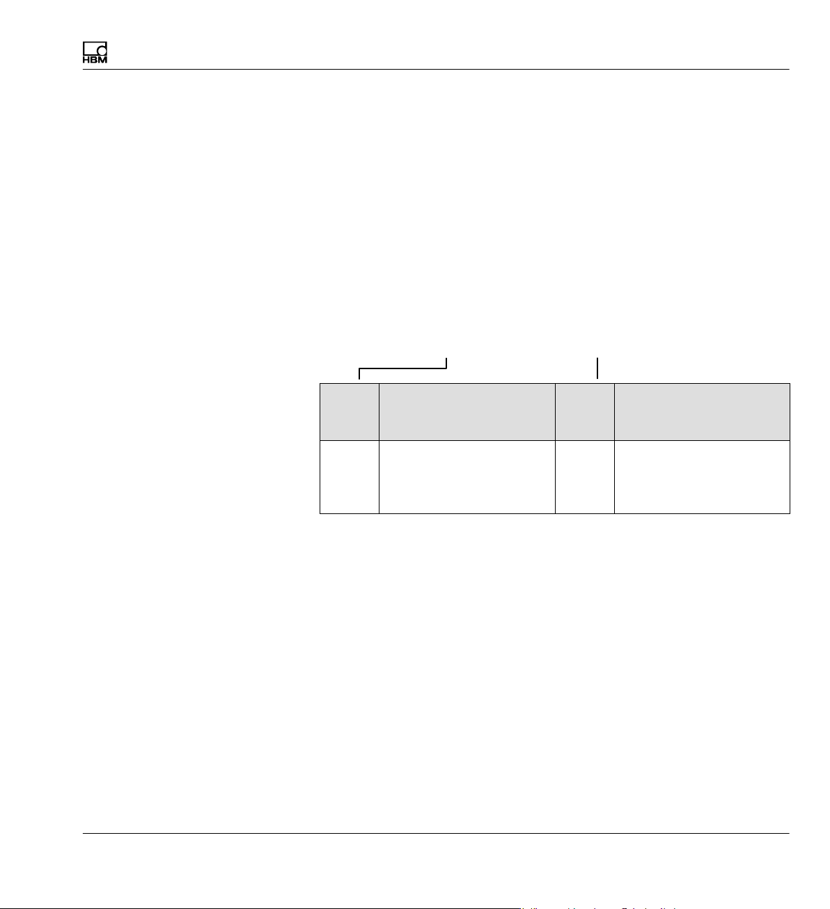
3.1 Degree of protection
The degree of protection given in the technical data indicates the suitability
of the housings for various ambient conditions and also the protection of
persons against potential risks when used. The letters IP (International Pro
tection) which are always present in the designation, are followed by two
digits. These indicate which degree of protection a housing offers against
contact or foreign objects (first digit) and moisture (second digit).
MGCplus devices are available with degree of protection IP20.
IP 2 0
Code
index
2 Protection against contact
Degree of protection
against contact and
foreign objects
with fingers, protection
against foreign objects
with > 12 mm
Code
index
0 No water protection
Degree of protection
against water
MGCplus A0534-30.0 HBM: public 17
Page 18

Introduction
Notes on documentation
3.2 Notes on documentation
The complete documentation for the MGCplus amplifier system includes the
following documents:
S The operating manual,
which explains manual operation of the device and how to perform mea
surements with it.
CD-ROMs containing the following documentation are included with every
system device:
S Operation with computer or terminal,
which contains commands for programming and measuring with com
puter or terminal.
S MGCplus Assistant,
Documentation of the program for parameterization and control of the
MGCplus measuring amplifier system.
This manual contains all the information required to operate the MGCplus.
Guides
Several guides are available to help you:
S The header shows you which section or sub-section you are currently
reading. For example:
Introduction
Notes on documentation
S See
è section 6 „Functions and symbols of the AB22A“ for explanations
of the AB22A display and control unit.
è Section 11 „Menu structure“ provides an overview of the drop-down
S
and setting menus of the display and control unit.
18 A0534-30.0 HBM: public MGCplus
Page 19

Introduction
System description
3.3 System description
The MGCplus system is structured modularly. Depending on the housing
variant, up to 16 slots are available for single and multi-channel amplifier
modules. Thus up to 128 measuring points can be measured in an
MGCplus.
Each amplifier module works independently through its own CPU. Data
preparation, for example taring, filtering and measuring range adjustment, is
carried out digitally. This eliminates the disadvantages of analog data prepa
ration, such as time and temperature-dependent drift, errors due to compo
nent tolerances, greatly limited flexibility and extensive circuitry. An essen
tial precondition for this is analog/digital conversion with no loss of
information. The digitally conditioned signal is directed to the internal bus.
For single-channel modules, two analog outputs (voltage) are available in
addition to the digital measured values.
An internal standard PC computer in credit-card format collects data with a
total sampling rate of up to 307,200 measured values per second (4-byte
integer format: 3-byte measured value + 1-byte status). All measurement
signals can be acquired in parallel, since each channel has its own ADU. No
Sample & Hold or Multiplexer is used in the MGCplus. This ensures continu
ous digital filtering and maximum signal stability.
Data is sent to an external computer or PLC via interfaces such as Ethernet.
A large part of the system functionality is implemented by device-internal
software (also called firmware). We therefore recommend you use our free
firmware updates and always keep your devices updated to the latest
firmware version. For further information go to www.hbm.com/downloads.
MGCplus A0534-30.0 HBM: public 19
Page 20

Introduction
System description
...
12 8
...
2400Hz
2400Hz
signal conditioning
Filtering, scaling,
zero balance, ...
2400Hz
Digital
CPU
8-channel
module
...
Digital signal
conditioning
Filtering
Scaling, zero
balance, ...
Single
channel
module
Fig. 3.1 Block diagram of MGCplus
"10V
Digital control inputs, limit
switches
...
CPU
CPU CPU
CPU
CAN
...
Profi-bus
CPU
Display
and
control
panel
Serial bus
Storage medium (optional)
Communication
processor CPxx
PC interface
Additional MGCplus
Synchronization
20 A0534-30.0 HBM: public MGCplus
Page 21
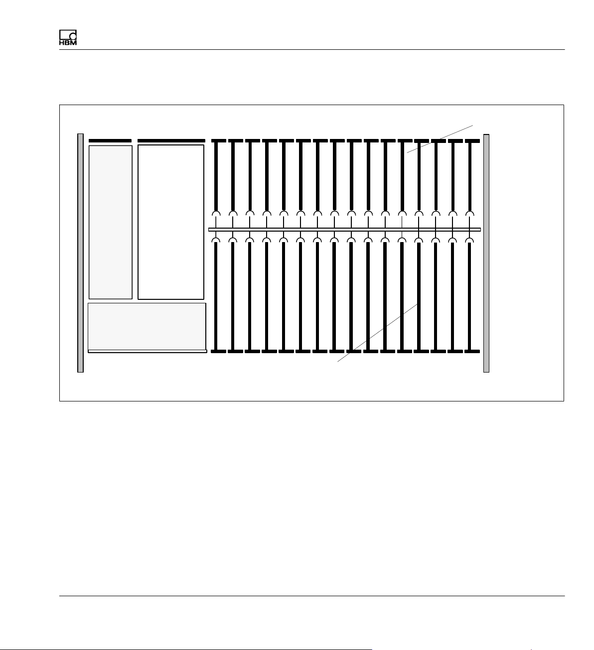
3.4 Layout of the MGCplus device
Introduction
Layout of the MGCplus device
Connection boards
(AP01i, AP815i, ...)
Power
supply
Communication
processor
AB22A
display and
control unit
CPxx
Amplifier
plug−in board
(ML30B, ML55B, ML801B...)
Fig. 3.2 Device layout with display and control unit AB22A
Double-width connection boards (AP03i, AP455i) must be plugged into the
odd-numbered slots. This also applies to the corresponding amplifiers, re
gardless of the width.
Double-width amplifiers (ML38B) must be plugged into the odd-numbered
slots. This also applies to the corresponding connection board, regardless of
the width.
When asynchronous modules are used (ML7XB with more than eight sub
channels), the sequence ‘asynchronous-synchronous-asynchronous’ is not
permissible.
MGCplus A0534-30.0 HBM: public 21
Page 22
Introduction
MGCplus housing designs
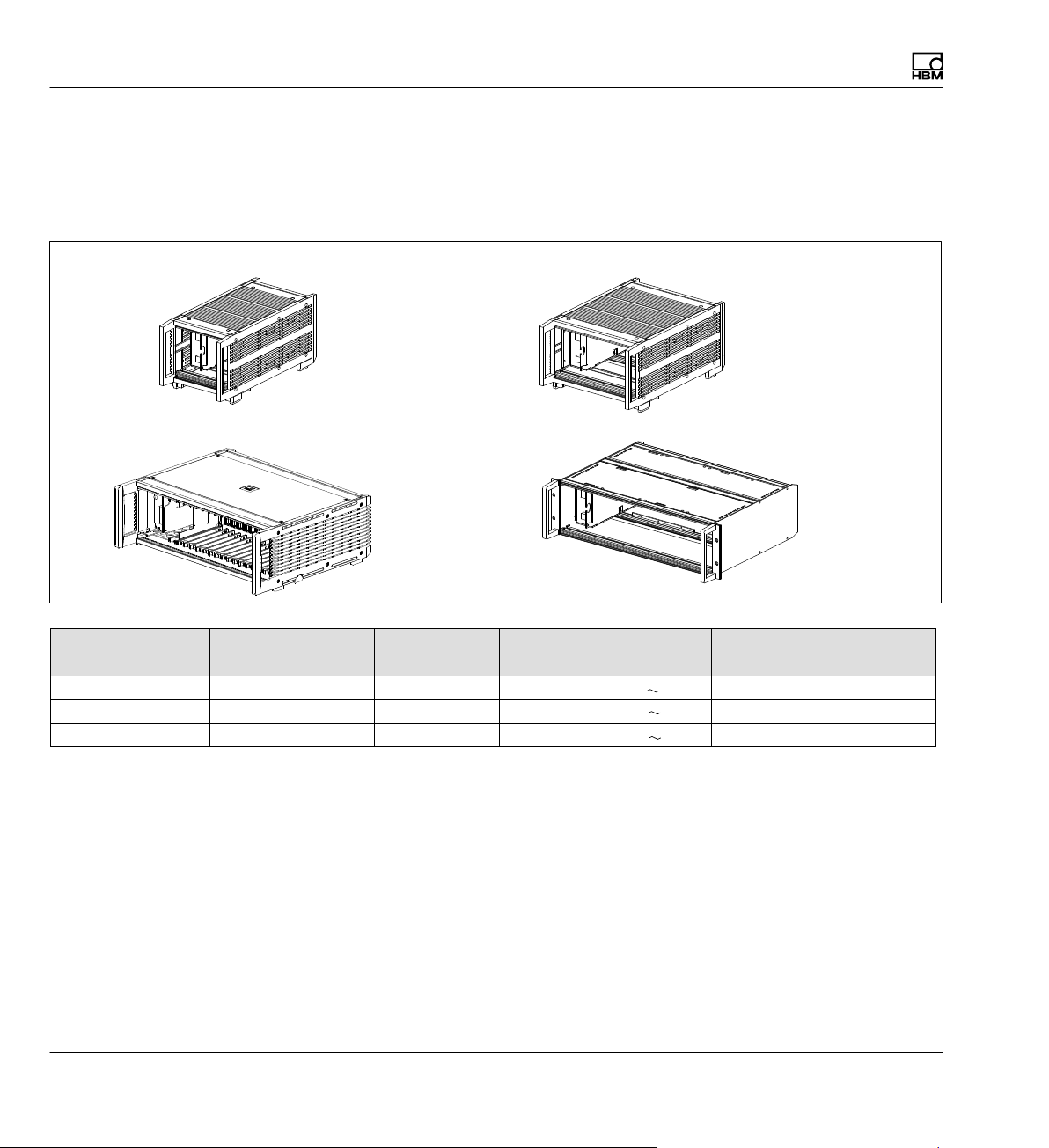
3.5 MGCplus housing designs
The MGCplus system is available with different housing versions
(dimensions in mm; 1 mm = 0.03937 inches):
Desktop housing TG009E (173x171x367) Desktop housing TG001E (255x171x367)
Desktop housing TG003E (458x171x367)
Desktop housing Rack frame Slots Supply voltage (V) Weight, approx. (kg)
TG001E − 6 230 (115) 5.9
TG003E ER003E 16 230 (115) 8.3 / 5.5
TG009E − 2 230 (115) 5.0
1)
With the NT030 power pack, the enclosures weigh about 150g less each
19” rack frame ER003E (482x133x375)
TG/ER
1)
1)
1)
All basic devices consist of the following components:
S AB22A display and control unit
S Amplifier modules (ML10B, ML30B, ML55B, ML801B ...)
S Housing
S Connection boards (AP01i, AP815i, ...)
S Power supply
Options:
S CP52 (Communication processor for communication with computer that
allows for data storage)
22 A0534-30.0 HBM: public MGCplus
Page 23
Introduction
MGCplus housing designs
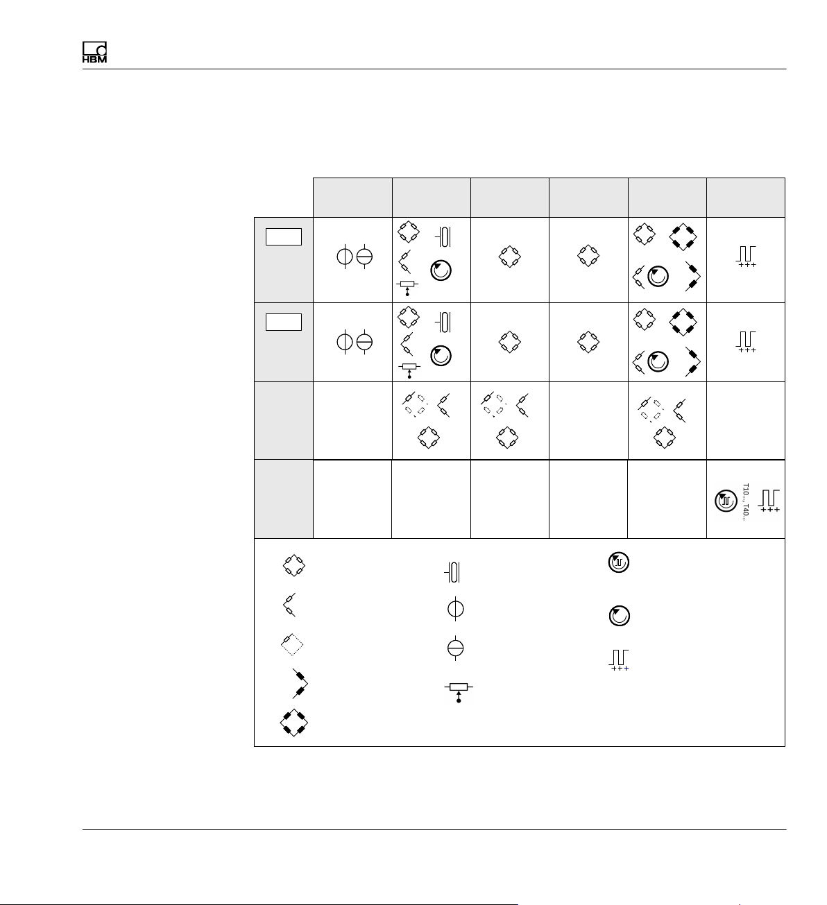
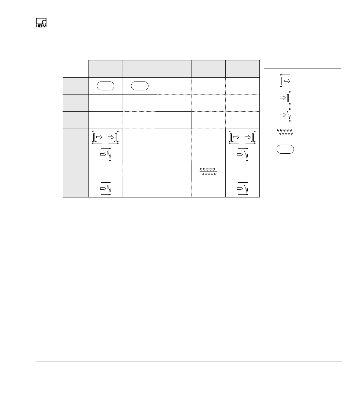
3.6 Possible amplifier/connection board combination
Single-channel amplifier
ML01B ML10B ML30B ML38B ML55B ML60B
TEDS
AP01i
TEDS
AP03i
AP14
AP17
SG full bridge circuit
SG half bridge circuit
R
1,4,5,B1
R
1,4,5,B1
R
Piezoresistive
transducer
Voltage
1,4,5,B1 1,4,5,B1
T3...T10
Torque / rotational speed
T3...T10
1,4,5,B1
Torque
T1, T4, T5, TB1
SG quarter bridge circuit
Inductive half bridge
Inductive full bridge
1)
For the combination of ML55B with AP14, a one-time zero calibration must always be
performed after setting up the measurement chain.
Current
Pulse counter, frequency
Potentiometric
transducers
MGCplus A0534-30.0 HBM: public 23
Page 24
Introduction
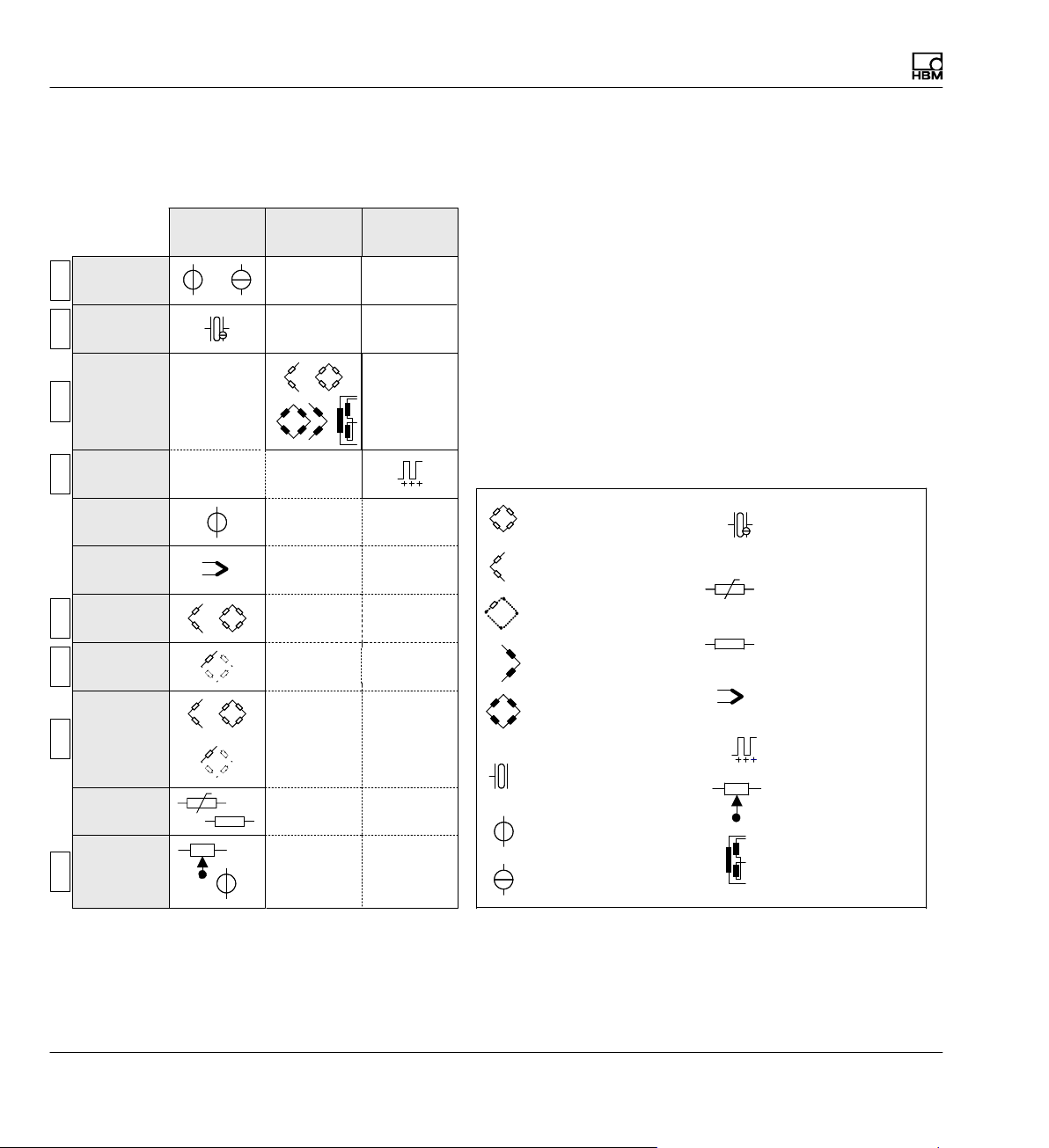
MGCplus housing designs
ML801B ML455 ML460
AP402i
TEDS
AP418i
TEDSTEDSTEDSTEDSTEDSTEDSTEDS
AP455i
AP455iS6
AP460i
Multi-channel amplifiers
AP801
AP801S6
AP809
AP810i
AP814Bi
AP815i
AP835
AP836i
SG full bridge circuit
SG half bridge circuit
SG quarter bridge circuit
Inductive half bridge
Inductive full bridge
R
Piezoresistive
transducer
Voltage
Current
Current−fed piezo−
electric transducer
Thermo−resistors
Thermo−resistors
PT100
PT
Ohmic resistor
Thermocouples
Pulse counter, frequency
Potentiometer
200 −5000
LVDT
24 A0534-30.0 HBM: public MGCplus
Page 25
Special function modules
Introduction
MGCplus housing designs
AP71
AP72
AP74
AP75
AP77
AP78
ML70B ML71B ML77B ML78B
CAN CAN
Serial I/O
ML74B
CANHEAD
Digital output
Digital input
Analog output
ProfiBus
CAN
CANBus
Serial I/O
CANHEAD HBM hardware
RS232, RS422,
RS485 I/O
MGCplus A0534-30.0 HBM: public 25
Page 26

Introduction
Installation of the CP52 communication processor
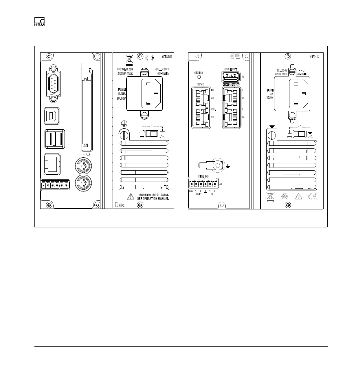
3.7 Installation of the CP52 communication processor
For type "D" housings (ER003D or TG001D, etc.) the existing communica
tion processor (CP22/CP42) can be replaced by the CP52 communication
processor.
► Loosen the screws on the old communication processor, the blind panel
(only with CP22) and the cover of the NT030 power supply unit.
► Remove the parts.
► Insert the new CP52 communication processor and screw it in place.
► Fit the power supply cover of the NT030 and screw the cover in place.
The process is similar when subsequently installing a CP52 communication
processor in an MGCplus housing (type "D" or type "E") that was initially
configured without a communication processor.
► Loosen the screws on the blind panels, if there are any, of the SY03 syn
chronization interface and the power supply cover.
► Remove the parts.
► Insert the new CP52 communication processor and screw it in place.
► Fit the power supply cover of the NT030 or NT040 and screw the cover
in place.
26 A0534-30.0 HBM: public MGCplus
Page 27
Introduction
Installation of the CP52 communication processor
CARDBUS
YE SLAVE
RD ERROR
GN MASTER
12
IN
CP42
SYN
OU
IN
C
T
RS 232
USB DEVICE
USB HOST
ETHERNET
CTRL I/O
24V 21 GND
OUT
Communication processor CP42, power supply
unit NT030
Communication processor CP52, power supply
unit NT040
Fig. 3.3 Rear views
If the communication processor is installed subsequently in a system where
none was present before, the housing cover must also be removed to check
the setting of the CP switch (S3). It must be set to "yes" so the system can
be started with the communication processor. Then the housing cover can
be closed again.
MGCplus A0534-30.0 HBM: public 27
Page 28
Introduction
Installation of the CP52 communication processor
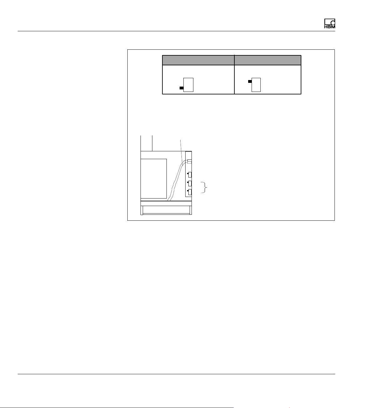
Without CP … View from above With CP … View from above
S3
CP
yes (1)
no (2)
S3
CP
yes (1)
no (2)
General plan of the interface switches(housing cover open, view from
above):
Housing
Flat ribbon
cable
S3
Power
supply
CP switch
p 2
Interface switch
S1
Fig. 3.4 General plan of the interface switches
Due to the new functions of the CP52 communication processor, a firmware
update of the AB22A display and control unit is necessary. The firmware
update program MGCpLoad and the latest firmware are available from
www.hbm.com/downloads.
28 A0534-30.0 HBM: public MGCplus
Page 29
Introduction
Conditions at the place of installation
3.8 Conditions at the place of installation
CAUTION
S Protect the devices in a desktop housing from moisture and dampness
or weather conditions such as rain, snow, etc.
S Make sure that you do not cover the ventilation openings at the side, the
openings for the power pack fan on the back side of the device and the
openings underneath the device.
S Do not expose the device to direct sunlight.
S Comply with the maximum permissible ambient temperatures for the sys
tem devices, as stated in the technical data sheet.
S For installation in 19" electrical enclosures, due to poorer heat dissipa
tion, measures must be taken to ensure that the maximum permitted am
bient temperature (refer to the technical data sheet) is not exceeded! We
recommend forced venting in any case and in especially critical cases
intermediate spaces between the upper and lower rack frames.
S The devices are classified in overvoltage category II, degree of pollution 2.
S Install the device so that it can be disconnected from the mains at any
time without difficulty.
S It is safe to operate the MGCplus up to an altitude of 2000 m.
MGCplus A0534-30.0 HBM: public 29
Page 30
Introduction
Maintenance and cleaning
3.9 Maintenance and cleaning
The MGCplus system devices are maintenance-free. Please note the follow
ing points when cleaning the housing:
CAUTION
Disconnect the mains plug from the socket before cleaning.
S Clean the housing with a soft, slightly damp (not wet!) cloth. You should
never use solvents, since this may damage the labeling on the front
panel and the display field.
S When cleaning, ensure that no liquid gets into the device or connections.
30 A0534-30.0 HBM: public MGCplus
Page 31

4 Connection
Mains
connection
Connection
Connecting the MGCplus in a tabletop housing/rack frame
4.1 Connecting the MGCplus in a tabletop housing/rack frame
4.1.1 Mains connection
The NT030 and NT040 power supply units are designed for a 115 - 230 V
connector and for a maximum configuration of 16 modules and connection
boards. Voltage adaptation to a 115V/230V network occurs automatically.
The power pack fan is temperature-controlled and is automatically switched
on only when necessary.
Housing ground
Grounding
switch
If the MGCplus is connected with the mains cable included with delivery, a
safe and reliable connection via the protective conductor is ensured.
The power pack is protected internally with a fine-wire fuse.
CAUTION
The power supply fuse may only be replaced by the manufacturer's service
personnel!
Grounding switch
In the factory setting (
zero with the protective conductor. If external devices (transducer, com
puter) have already set up this connection resulting in ground loops (hum-
pickups), the grounding switch must be opened (
), the grounding switch connects supply voltage
).
MGCplus A0534-30.0 HBM: public 31
Page 32

Connection
Connecting the MGCplus in a tabletop housing/rack frame
4.1.2 Synchronization of multiple CP52 devices
4.1.2.1 Synchronization of multiple CP52 devices via a synchronization jack
Connected devices are automatically detected and synchronized when syn
chronization jacks are occupied. Connect the master device with the first
slave device (Sync In, X1) via the output jack (Sync Out, X2). If there are
additional slave devices, connect the input jack (Sync In, X1) in turn with the
output jack (Sync Out, X2) of the previous slave device (Sync Out, X2).
LED Sync Out Status
Green Device is ready for operation and the time signal is
Yellow There is no valid time signal present on the Sync out
LED Sync In Status
Green The device is in slave mode, correctly synchronized
Yellow The device is in slave mode but is not synchronized.
present on the Sync output.
put.
and ready for operation.
Synchronization sockets
32 A0534-30.0 HBM: public MGCplus
Page 33

Connection
Connecting the MGCplus in a tabletop housing/rack frame
If several MGCplus systems are to be synchronized with each other, each
system must be equipped with a CP52 communications processor. To syn
chronize MGCplus systems with CP52, you need a synchronization cable
with the HBM part number 1-KAB2125-2 (2 m in length).
Fig. 4.1 Example of synchronizing two MGCplus systems equipped with CP52.
The overall length of the synchronization chain (total length of cable be
tween the sync master and the last sync slave) must be less than 150 m. A
termination resistor should be used if the line length is >15 m. We recom
mend that you attach a termination resistor connector to the Sync Out
socket (X2) of the last sync slave. This connector is available from HBM on
request. The maximum number of MGCplus units that can be synchronized
is 32.
MGCplus A0534-30.0 HBM: public 33
Page 34

Connection
Connecting the MGCplus in a tabletop housing/rack frame
Powering up the system
When connecting the system, the sync slaves must be connected first.
Connect the system that will work as the sync master last of all.
4.1.3 Synchronization of CP52 with CP22/CP42
The synchronization jack enables MGCplus systems with CP52 to be
synchronized with MGCplus systems with CP22/CP42.
To do this note the following points:
Both CP42 and CP52 can be the synchronization master. CP22 can only be
a synchronization slave.
Use the following cables for this:
1-KAB2126-2: CP52 (master) to CP22/CP42 (slave)
1-KAB2127-2: CP42 (master) to CP52 (slave)
The synchronization status for CP22/CP42 is indicated by a multicolor LED.
34 A0534-30.0 HBM: public MGCplus
Page 35

Connection
Connecting the MGCplus in a tabletop housing/rack frame
CP42
RS 232
CARDBUS
USB DEVICE
USB HOST
YE SLAVE
CTRL I/O
RD ERROR
GN MASTER
IN
SYNC
OUT
ETHERNET
24V 21GND12
OUT
IN
Fig. 4.2 Example of synchronizing two MGCplus systems equipped with CP52
and CP42.
MGCplus A0534-30.0 HBM: public 35
Page 36

Connection
Shielding design
4.2 Shielding design
Sources of interference can cause electromagnetic fields which can induce
interference voltages inductively or capacitively via the connection cable
and device housing in the measuring circuit and therefore interfere with the
device function. It must be ensured that the devices used in the system also
do not transmit any electromagnetic interference. Electromagnetic compati
bility (EMC), which encompasses both the required electromagnetic interfer
ence immunity (EMI) and the permissible electromagnetic interference emis
sions (EME), has become increasingly important over the years.
The HBM Greenline shielding design
The measurement chain is completely enclosed by a Faraday cage by
appropriate routing of the cable shield. The cable shield is extensively con
nected with the transducer housing and is routed via the conductive plug to
the amplifier housing. The influence of electromagnetic interference is signif
icantly reduced by these measures.
The conductive housing
ensures the connection
to the plug or device
housing
Signal-carrying
contacts
Fig. 4.3 Routing of the cable shield on the plug
The cable shield is connected with the
conductive housing via strain relief
36 A0534-30.0 HBM: public MGCplus
Page 37

Connection
Shielding design
Notice
All parts of the measurement chain (including all cable connection points
such as plugs and couplings) must be surrounded by a closed EMC-tested
shield. Shield junctions must represent a full contact, closed and low-imped
ance connection. This is the case for original HBM plug connections.
Ground connection and grounding
As the signal ground and shielding are separated in EMC-compliant cabling,
the shielding can be connected at more than one point to the ground, i.e. via
the transducer (metal housing) and the amplifier (housing is connected to
the ground conductor).
If there are differences in potential in the measuring system, a potential
compensating line must be laid (recommended value: highly flexible
stranded wire, wire cross section 10mm
set up so they are physically separated from current-carrying power lines.
Ideally, cable ducts made of sheet metal with an internal partition should be
used. Signal ground, ground and shielding must be laid out separated as
much possible.
2
). Signal and data leads must be
In order to minimize the effect of electromagnetic interference and differ
ences in potential, the signal ground and ground (or shielding) are designed
to be physically separate in the HBM devices. The ground connection or a
separate mains protective conductor should serve as the ground connec
tion, as is the case for potential compensation in buildings, for example. The
ground cable should not be connected to a radiator body, water pipe or simi
lar objects.
Connecting transducers with double shield technique
MGCplus A0534-30.0 HBM: public 37
Page 38

Connection
Shielding design
AP01i
AP14
AP03i
AP455i
1
9
A
B
G
C
15
8
Measurement signal (-)
Measurement signal (+)
2
1
4
3
Bridge excitation voltage (-)
Bridge excitation voltage (+)
Cable shield
Sense lead (+)
Sense lead (-)
15
Hsg.
13
12
A
8
5
6
B
C
D
Hsg.
F
G
4
RB / 2 (on the transducer)
Hsg. = Housing
HBM recommends this connection technique for measuring amplifiers
ML10B, ML30B, ML38B, ML55B and ML455 with connection boards
AP01i, AP03i, AP14 and AP455i with very small measuring ranges, in
environments especially subject to interference and when long cables
are used.
F
E
D
This applies to all bridge connections.
With cable lengths >50 m, a resistor with half the value of the bridge
resistance (R_B/2) must be connected in each sense lead of the trans
ducer.
38 A0534-30.0 HBM: public MGCplus
Page 39

Connection
Connecting the transducer
Measurement
signal (+)
Bridge excitation
2
1
4
3
Feedback
voltage (-)
Bridge excitation
voltage (+)
Measurement
signal (-)
Cable shield
Sense lead (+)
Sense lead (-)
bridges
4.3 Connecting the transducer
1)
Transducers with four-wire configuration
If you connect a transducer with a 4-wire cable, you must connect the sense
lead with the corresponding bridge excitation circuit in the transducer plug
(sense line (-) with bridge excitation voltage (-) and sense lead (+) with
bridge excitation voltage (+)
Important
1)
. A cable extension may only be implemented
with 6-wire configuration.
TEDS
TEDS data
AP01i
AP455i
1
8
4
9
4.3.1 Connecting separate TEDS modules
9
15
Single-channel amplifier MLxx (together with connection board AP01i) must
Important
have at least hardware revision 1.32 or higher.
1)
For cable lengths >50m, a resistor of half the value of the bridge resistance (RB/2) must be activated on the transducer instead of each
feedback bridge. If the transducers are calibrated in a 6-wire configuration, resistors must be activated directly into the sense lead.
MGCplus A0534-30.0 HBM: public 39
Page 40

Connection
Connecting separate TEDS modules
AP402i
4x
View of the mating connector
(solder side)
5
6
4
TEDS
TEDS data
Hsg.
1
3
2
1
4
3
5
40 A0534-30.0 HBM: public MGCplus
Page 41

TEDS
TEDS data
AP460i
10
1
2
4
Hsg.
9
8
Cable color code:
wh= white;
bk= black;
bu= blue;
rd= red;
ye= yellow;
gn= green;
gy= gray
8
1
67
910
3
2
Connection
Connecting separate TEDS modules
5
4
MGCplus A0534-30.0 HBM: public 41
Page 42

Connection
SG full bridges, inductive full bridges
4.3.2 SG full bridges, inductive full bridges
AP01i
AP03i
AP455iS6
AP14
AP455i
1
6
Hsg.
5
4
3
2
1
2
3
4
5
6
1
9
15
8
wh
Measurement signal (+)
bk
Bridge excitation
2
1
4
3
b
u
r
d
ye
gn
g
y
voltage (-)
Bridge excitation
voltage (+)
Measurement signal (-)
Cable shield
Sense lead (+)
Sense lead (-)
8
5
6
15
Hsg.
13
12
A
C
A
B
C
D
Hsg.
F
G
F
EB
G
D
Cable color code: wh= white; bk= black; bu= blue; rd= red; ye= yellow; gn= green; gy= gray
42 A0534-30.0 HBM: public MGCplus
Page 43

AP810i/AP815i
1
14
Subchannel 1...4
13
1
13
25
14
25
Subchannel 5...8
Full bridge circuits on AP810i/AP815i
4.3.3 Full bridge circuits on AP810i/AP815i
Subchannel
1/5
wh
Measurement signal (+)
bk
Bridge excitation
2
1
4
3
bu
rd
ye
gn
gy
voltage (-)
Bridge excitation
voltage (+)
Measurement signal (-)
Cable shield
Sense lead (+)
Sense lead (-)
)
2
1
3
15
Hsg.
16
14
Cable color code: wh= white; bk= black; bu= blue; rd= red; ye= yellow; gn= green; gy= gray
Subchannel
2/6
5
4
6
18
Hsg. Hsg.
19
17
Subchannel
3/7
8
7
9
21
22
20
Connection
Subchannel
4/8
11
10
12
24
Hsg.
25
23
MGCplus A0534-30.0 HBM: public 43
Page 44

Connection
Strain gage half bridges, inductive half bridge circuits
4.3.4 Strain gage half bridges, inductive half bridge circuits
AP01i
AP03i
AP455iS6
AP14
AP455i
1
Hsg.
5
6
4
3
2
1
2
3
5
6
A
1
9
15
8
wh
Measurement signal (+)
bk
Bridge excitation
2
1
3
b
u
ye
gn
g
y
voltage (-)
Bridge excitation
voltage (+)
Cable shield
Sense lead (+)
Sense lead (-)
8
5
6
Hsg. Hsg.
13
12
F
EB
G
D
C
A
B
C
F
G
Cable color code: wh= white; bk= black; bu= blue; rd= red; ye= yellow; gn= green; gy= gray
44 A0534-30.0 HBM: public MGCplus
Page 45

4.3.5 LVDT transducers
Connection
LVDT transducers
LVDT transducers
Measurement signal (+)
Bridge excitation voltage (-)
Bridge excitation voltage (+)
Measurement signal (-)
Cable shield
Sense lead (+)
Sense lead (-)
)
AP455i
8
5
6
15
Hsg.
13
12
AP455iS6
5
6
4
3
1
2
1
2
3
4
Hsg.
5
6
MGCplus A0534-30.0 HBM: public 45
Page 46

Connection
Strain gage half bridges on AP810i
AP810i
4.3.6 Strain gage half bridges on AP810i
1
14
1/5
Subchannel
Subchannel
2/6
Subchannel
3/7
Subchannel
4/8
Subchannel
1...4
13
1
25
14
2
1
rd
wh/rd
wh/gn
Sense lead (-)
Bridge excitation voltage (-)
Measurement signal (+)
Cable shield
Subchannel
5...8
13
25
3
wh/br
br
Bridge excitation voltage (+)
Sense lead (+)
16
14
1
2
Hsg.
3
17
20
4
5
Hsg. Hsg.
6
19
22
23
7
8
9
10
11
Hsg.
12
25
46 A0534-30.0 HBM: public MGCplus
Page 47

AP815i
Connection
Strain gage half bridges on AP815i
4.3.7 Strain gage half bridges on AP815i
1
14
1/5
Subchannel
Subchannel
2/6
Subchannel
3/7
Subchannel
4/8
Subchannel
1...4
13
1
25
14
Subchannel
2
1
4
5...8
13
25
3
rd
wh/rd
wh/gn
gn
wh/br
br
Sense lead (-)
Bridge excitation voltage (-)
Measurement signal (+)
Cable shield
Measurement signal (-)
Bridge excitation voltage (+)
Sense lead (+)
1)
1)
16
14
Hsg.
15
17
1
2
4
5
Hsg. Hsg.
18
3
6
19
20
21
22
23
7
8
10
11
Hsg.
24
9
12
25
AP815i can measure decentralized half bridge circuits for which the active
SGs are separated by a line.
1)
With decentralized half bridge circuits the measured value must be acquired at both ends of the connecting line between the active SGs.
With standard half bridge circuits a connector can also be bridged.
MGCplus A0534-30.0 HBM: public 47
Page 48

Connection
Single strain gage
4.3.8 Single strain gage
4.3.8.1 Single strain gage on AP14
AP14
1
9
15
8
SG
SG
Three-wire connection Four-wire connection
Sense lead (-)
Excitation voltage (-)
Excitation voltage (+)
Measurement signal (+),
sense lead (+)
12
5
Hsg.
15
8
48 A0534-30.0 HBM: public MGCplus
Page 49

AP814Bi
Connection
Single strain gage
4.3.8.2 Single strain gage on AP814Bi
1
14
1
1
2
3
Subchannels
4
65
7
8
Subchannel 1...8
13
25
Measurement signal (+),
excitation voltage (+)
5
2
5
5
8
SG
Cable shield
Excitation voltage (-)
Sense lead (-)
Hsg.
Hsg.
15
14
Hsg.15Hsg.
16
8
1
3
17
Hsg.5Hsg.
Hsg.
Hsg.18Hsg.
19
4
6
Hsg.
Hsg.
15
20
Hsg.21Hsg.
22
8
7
9
Hsg.11Hsg.
23
10
Hsg.24Hsg.Hsg.
25
12
Three-wire connection
Cable color code: wh= white; bk= black; bu= blue; rd= red; ye= yellow; gn= green; gy= gray
MGCplus A0534-30.0 HBM: public 49
Page 50

Connection
Single strain gage
AP815i
4.3.8.3 Single strain gage on AP815i
1
14
1/5
Subchannel
Subchannel
2/6
Subchannel
3/7
Subchannel
4/8
Subchannel
1...4
13
1
25
14
SG
2
2'
wh/rd
rd
Subchannel
5...8
13
25
1
4
wh/gn
gn
Excitation voltage (-)
Sense lead (-)
Cable shield
Measurement signal (+),
sense lead (+)
Excitation voltage (+)
15
14
Hsg.
1
4
17
Hsg. Hsg.
2
5
18
20
21
7
10
23
Hsg.
8
11
24
Cable color code: wh= white; bk= black; bu= blue; rd= red; ye= yellow; gn= green; gy= gray
50 A0534-30.0 HBM: public MGCplus
Page 51

1
13
13
1
AP815i
14
Subchannel
1...4
25
14
Subchannel
5...8
25
SG
Connection
SG chains and strain gage rosettes on AP815i
4.3.9 SG chains and strain gage rosettes on AP815i
Subchannel
1
2
2'
SG
SG
4/8
5
3/7
SG
2/6
SG
1
1
4
Excitation voltage (-)
Sense lead (-)
Cable shield
Measurement signal (+),
sense lead (+)
Excitation voltage (+)
1
14
Hsg.
2
15
Subchannel
2/6
Subchannel
5
18
3/7
Subchannel
4/8
Subchannel
5
8
21
11
24
2
15
You can operate a maximum of eight SGs at 120 ohms with a 5-V current
feed. Make certain that sensor point 2' of the SG chain is as close as possi
ble for the individual strain gages and the distances between the individual
strain gages are short.
MGCplus A0534-30.0 HBM: public 51
Page 52

Connection
SG chains and strain gage rosettes on AP815i
If the distances between the individual strain gages cannot be kept small
(for example two 90 strain gage rosettes in different places), they must be
connected as follows:
1
13
1
13
AP815i
14
Subchannel
25
14
Subchannel
25
1...4
5...8
SG2 SG1
SG4 SG3
Subchannel
1
2
2'
1
4
Excitation voltage (-)
Sense lead (-)
Cable shield
Measurement signal (+),
sense lead (+)
Excitation voltage (+)
1
14
Hsg.
2
15
Subchannel
2
5
18
Subchannel
5
2
2'
1
4
Excitation voltage (-)
Sense lead (-)
Cable shield
Measurement signal (+),
sense lead (+)
Excitation voltage (+)
1
14
Hsg.
2
15
Subchannel
6
5
18
52 A0534-30.0 HBM: public MGCplus
Page 53

Connection
Torque flange T10 series, T40 series
4.3.10 Torque flange T10 series, T40 series
4.3.10.1 Torque measurement
Plug 1
Md
23
7/5 6
4
1
bk
bu
r
d
w
h
ye
gn
g
y
Power supply (0V)
Supply voltage (18V ... 30 V)
Torque measurement signal, frequency output (+)
Torque measurement signal, frequency output (-)
Cable shield
Calibration signal trigger (approx. 5V)
Ground
1)
AP17
1
9
15
8
5
6
12
13
Hsg.
14
8
Cable color code: wh= white; bk= black; bu= blue; rd= red; ye= yellow; gn= green; gy= gray
1)
Does not apply to version KF1.
MGCplus A0534-30.0 HBM: public 53
Page 54

Connection
Torque flange T10 series, T40 series
AP460i
Plug 1
Md
7/5
r
4
1
d
w
h
ye
gn
g
y
Torque measurement signal, frequency output (+)
Torque measurement signal, frequency output (-)
Cable shield
Ground
1
2
Hsg.
10
Cable color code: wh= white; bk= black; bu= blue; rd= red; ye= yellow; gn= green; gy= gray
8
1
67
910
3
2
5
4
Information
The torque flanges must be powered externally.
54 A0534-30.0 HBM: public MGCplus
Page 55

Connection
Torque flange T10 series, T40 series
4.3.10.2 Rotational speed measurement (symmetrical signals)
AP17
1
8
9
15
Plug 2
81
6
7
3
n
bk
and
bu
rd
wh
gn
g
y
Ground
Rotational speed measurement signal, 0 (+)
Rotational speed measurement signal, 0 (-)
Rotational speed measurement signal, 90 (-)
Cable shield
Rotational speed measurement signal, 90 (+)
8
12
13
14
Hsg.
15
Cable color code: wh= white; bk= black; bu= blue; rd= red; ye= yellow; gn= green; gy= gray
MGCplus A0534-30.0 HBM: public 55
Page 56

Connection
Torque flange T10 series, T40 series
AP460i
Plug 2
n
81
3
6
7
ye
rd
wh
gn
g
y
Ground
Rotational speed measurement signal, 0 (+)
Rotational speed measurement signal, 0 (-)
Rotational speed measurement signal, 90 (-)
Cable shield
Rotational speed measurement signal, 90 (+)
10
1
2
4
Hsg.
3
Cable color code: wh= white; bk= black; bu= blue; rd= red; ye= yellow; gn= green; gy= gray
8
1
67
910
3
2
5
4
56 A0534-30.0 HBM: public MGCplus
Page 57

Connection
Torque flange T10 series, T40 series
4.3.10.3 Rotational speed measurement (symmetrical signals) with reference pulse
AP17
1
8
Plug 2
n
81
4
3
6
7
2
ye
rd
wh
gn
b
u
bk
g
y
Ground
Rotational speed measurement signal, 0 (+)
Rotational speed measurement signal, 0 (-)
Rotational speed measurement signal, 90 (-)
Cable shield
Reference signal (+)
Reference signal (-)
Rotational speed measurement signal, 90 (+)
5V (out)
8
12
13
14
Hsg.
2
3
15
11
9
15
Cable color code: wh= white; bk= black; bu= blue; rd= red; ye= yellow; gn= green; gy= gray
MGCplus A0534-30.0 HBM: public 57
Page 58

Connection
Torque flange T10 series, T40 series
AP460i
Plug 2
n
81
3
4
6
7
2
ye
rd
wh
gn
b
u
bk
g
y
Ground
Rotational speed measurement signal, 0 (+)
Rotational speed measurement signal, 0 (-)
Rotational speed measurement signal, 90 (-)
Cable shield
Reference signal (+)
Reference signal (-)
Rotational speed measurement signal, 90 (+)
10
1
2
4
Hsg.
5
6
3
Cable color code: wh= white; bk= black; bu= blue; rd= red; ye= yellow; gn= green; gy= gray
8
1
67
910
3
2
5
4
58 A0534-30.0 HBM: public MGCplus
Page 59

Connection
Torque shaft (T4A, T5, TB1A)
4.3.11 Torque shaft (T4A, T5, TB1A)
4.3.11.1 Torque measurement (slip rings or direct cable connection)
AP01i
AP14
2)
AP03i
AP455i
A
F
E
B
G
D
C
A
B
C
D
F
G
wh
bk
2
1
3
Feedback bridges for
transducer in a four wire
configuration *
2)
SG full bridge only
*)
Transducer in a 6-wire configuration: see connection diagram
page 42
b
u
r
d
4
ye
Measurement signal (+)
Bridge excitation
voltage (-)
Bridge excitation
voltage (+)
Measurement signal (-)
Cable shield
Sense lead (+)
Sense lead (-)
1
9
15
8
8
5
6
15
Hsg. Hsg.
13
12
Cable color code: wh= white; bk= black; bu= blue; rd= red; ye= yellow; gn= green; gy= gray
MGCplus A0534-30.0 HBM: public 59
Page 60

Connection
Torque shaft (T4A, T5, TB1A)
Jumper (factory settings 0V)
Supply voltage +16V
No function (for special versions only)
No function (for special versions only)
Supply voltage +8V
Supply voltage +5V
Connection board AP 460 (side view)
60 A0534-30.0 HBM: public MGCplus
Page 61

Connection
Torque shaft (T4A, T5, TB1A)
4.3.11.2 Rotational speed measurement with inductive transducers
AP460i
Rotational speed
Inductive
measurement signal
Rotational speed
measurement signal
(+)
U
= 30V
max
(-)
tachometer
(T-R coil)
Please note the setting information for T-R coils on page 152.
67
8
1
910
2
3
5
4
1
1 k 5 k
5 V
2
MGCplus A0534-30.0 HBM: public 61
Page 62

Connection
Thermocouples
4.3.12 Thermocouples
Thermocouple
Compensating
Compensating
line
(-)
(+)
line
Miniature thermo connector (see
table for matching type)
AP809
-
−
+
+
Miniature thermo connector, uncompensated
Type Thermal material 1 (+) Thermal material 2 (-)
J Iron Copper-nickel
K Nickel‐chrome (color code
green)
Nickel‐aluminum (color code
white)
T Copper Copper-nickel
62 A0534-30.0 HBM: public MGCplus
Page 63

4.3.13 DC voltage sources
Maximum input voltage against
ground = 12V
DC voltage sources
AP01i AP03i
1
9
15
8
A
B
C
F
E
G
D
Connection
U
(+)
Supply voltage zero
1)
(-)
Cable shield
1)
With a potential-free DC voltage source you must connect pin 15 with pin 6.
8
6
15
Hsg. Hsg.
A
C
D
MGCplus A0534-30.0 HBM: public 63
Page 64

Connection
DC voltage sources
AP402i
Maximum input voltage against
ground = " 100V
U
(+)
(-)
Cable shield
Hsg.
4x
1
4
5
6
1
4
3
2
64 A0534-30.0 HBM: public MGCplus
Page 65

Connection
DC voltage sources
Maximum input voltage against
ground = +50V
(+)
U
(-)
AP801
Hsg.
U
Supply voltage 8V/16V
Power supply 0V
*) For information on switching the supply voltage see next page
AP801S6
41
2
(+)
(-)
*)
Hsg.
3
1
2
3
4
MGCplus A0534-30.0 HBM: public 65
Page 66

Connection
DC voltage sources
Supply voltage +16V
No function (for special versions only)
Jumper
Connection board AP 801S6 (side view)
No function (for special versions only)
Supply voltage +8V
66 A0534-30.0 HBM: public MGCplus
Page 67

AP402i
4x
Connection
DC voltage sources
5
6
4
U
Supply voltage 5V/8V/16V
Power supply 0V
*)
For information on switching the supply voltage see next illustration
*)
Jumper
1
3
2
(+)
(−)
1
4
6
3
Hsg.
Supply voltage +5V
Supply voltage +8V
Supply voltage +16V
No function (factory setting)
Connection board AP402i (side view)
MGCplus A0534-30.0 HBM: public 67
Page 68

Connection
DC voltage sources
AP836i
1
13
AP836i
1
Subchannels
2/61/5 3/7 4/8
14
Subchannel 1...4
25
Subchannel 5...8
U
0 V
(+)
B
U
OUT
Bridge excitation voltage (+)
Sense lead (+)
Measurement signal (+)
Measurement signal (-)
Cable shield
Sense lead (-)
Bridge excitation voltage (-)
1)
16
15
14
3
2
Hsg.
1
19
18
17
Hsg.
6
9
22
5
8
21
Hsg.
20
4
7
12
25
24
23
10
Common signal and supply voltage zero, power line not corrected on one side.
Since the bridge excitation voltage used to supply the active transducer is symmetrical to GND/ground, the
design of the active transducer must without exception be potential-free!
Subchannels
2/61/5 3/7 4/8
14
11
Hsg.
Subchannel 1...4
13
25
Ub(-)
U
(+)
B
U_
OUT
0 V
Subchannel 5...8
Bridge excitation voltage (+)
Sense lead (+)
Measurement signal (+)
Measurement signal (-)
Cable shield
Sense lead (-)
Bridge excitation voltage (-)
1)
16
15
14
3
2
Hsg.
1
19
18
17
Hsg.
6
9
22
5
8
21
Hsg.
20
4
7
12
25
11
24
Hsg.
23
10
Separate signal and supply voltage zero, power lines not corrected
Since the bridge excitation voltage used to supply the active transducer is symmetrical to GND/ground, the
design of the active transducer must without exception be potential-free!
68 A0534-30.0 HBM: public MGCplus
Page 69

Connection
DC voltage sources
AP836i
1
13
AP836i
1
Subchannels
2/61/5 3/7 4/8
14
Subchannel 1...4
25
Subchannel 5...8
U
(+)
B
U_
OUT
0 V
Bridge excitation voltage (+)
Sense lead (+)
Measurement signal (+)
Measurement signal (-)
Cable shield
Sense lead (-)
Bridge excitation voltage (-)
1)
16
15
14
Hsg.
3
2
1
19
18
17
Hsg.
6
22
5
21
Hsg.
20
4
Common signal and supply voltage zero, power lines fully corrected.
Since the bridge excitation voltage used to supply the active transducer is symmetrical to GND/ground,
the design of the active transducer must without exception be potential-free!
Subchannels
2/61/5 3/7 4/8
14
12
9
25
8
11
24
Hsg.
23
10
7
Subchannel 1...4
13
25
U
(+)
B
U_
OUT
0 V
U
(-)
B
Subchannel 5...8
Bridge excitation voltage (+)
Sense lead (+)
Measurement signal (+)
Measurement signal (-)
Cable shield
Sense lead (-)
Bridge excitation voltage (-)
1)
16
15
14
Hsg.
3
2
1
19
18
17
Hsg.
6
22
5
21
Hsg.
20
4
12
9
25
8
11
24
Hsg.
23
10
7
Separate signal and supply voltage zero, power lines fully corrected.
Since the bridge excitation voltage used to supply the active transducer is symmetrical to GND/ground, the
design of the active transducer must without exception be potential-free!
MGCplus A0534-30.0 HBM: public 69
Page 70

Connection
DC power sources
4.3.14 DC power sources
Maximum input voltage against
ground = 12V
AP01i AP03i
1
9
15
8
A
B
C
F
E
G
D
Supply voltage zero
(-)
6
C
I
(+)
Cable shield
5
Hsg.
B
Hsg.
70 A0534-30.0 HBM: public MGCplus
Page 71

Maximum input voltage against
ground = ±100V
AP402i
4x
Connection
DC power sources
5
6
1
4
3
2
(-)
4
I
(+)
Cable shield
2
Hsg.
MGCplus A0534-30.0 HBM: public 71
Page 72

Connection
Resistors, Pt100
4.3.15 Resistors, Pt100
AP835
1
2
Excitation voltage (-)
Measurement signal (-)
R
Cable shield
Measurement signal (+)
Excitation voltage (+)
4
3
1
2
Hsg.
3
4
72 A0534-30.0 HBM: public MGCplus
Page 73

Frequency measurement without directional signal
4.3.16 Frequency measurement without directional signal
AP01i AP03i
1
9
15
8
Connection
A
F
EB
G
D
C
Frequency
generator/
pulse
generator
Supply voltage zero
Cable shield
Rotational speed/pulse
signal 1 (frequency f1)
8
12
Deactivate the analysis of the f2 signal in this mode (factory setting: Off), see page 159.
A
Hsg.Hsg.
G
MGCplus A0534-30.0 HBM: public 73
Page 74

Connection
Frequency measurement with directional signal
4.3.17 Frequency measurement with directional signal
AP01i AP03i
1
9
15
8
A
B
G
C
F
E
D
Frequency
generator /
pulse
generator
Supply voltage zero
Cable shield
Rotational speed/pulse
signal 1 (frequency f1)
Pulse signal 2 (frequency f2)
8
12
15
Activate the analysis of the f_2 signal in this mode (factory setting: Off), see page 159
A
Hsg.Hsg.
G
D
74 A0534-30.0 HBM: public MGCplus
Page 75

4.3.18 Pulse counting, single-pole
Connection
Pulse counting, single-pole
Industrial
pulse generators
Zero index
Transducer error
AP01i AP03i
1
8
8
f
2
15
f
1
12
6
5
AP460i
9
15
A
F
EB
G
D
C
A
D
G
C
10
3
1
5
AP17
1
8
15
12
2
9
15
8
B
MGCplus A0534-30.0 HBM: public 75
Page 76

Connection
Pulse counting, differential
4.3.19 Pulse counting, differential
Industrial
pulse generators
Zero index signal +
Zero index signal -
Transducer error
f1+
f
f2-
f
AP17
1
9
15
8
2
3
12
-
1
13
14
+
2
15
AP460i
5
6
1
2
4
3
76 A0534-30.0 HBM: public MGCplus
Page 77

4.3.20 Active piezoelectric transducers
* Use special coaxial cable
Shield
Piezoelectric
transducer with
preamplifier
(with
T‐ID/TEDS for
AP418i)
Connection
Active piezoelectric transducers
AP418i
Input *
Information
Information about AP418i connection boards:
When laying transducer cables outside of enclosed areas or with cable
lengths greater than 30 m between the connection board and transducer,
the sensor cables must be designed with an additional, separately grounded
shield to ensure overvoltage protection. This can be done for example by
laying the cable in a metallic pipe or using double-shielded cable, in which
case the outer shield must be connected to ground potential or protective
conductor potential where it is close to the connection board (for example
where it enters the switch cabinet). HBM recommends Triaxial cable for this
purpose.
MGCplus A0534-30.0 HBM: public 77
Page 78

Connection
Piezoresistive transducers
4.3.21 Piezoresistive transducers
AP01i AP03i
1
9
15
8
A
G
C
F
EB
D
15
Hsg.
13
12
8
5
6
A
B
C
D
Hsg.
F
G
Measurement signal (+)
Bridge excitation
2
1
4
3
voltage (-)
Bridge excitation
voltage (+)
Measurement signal (-)
Cable shield
Sense lead (+)
Sense lead (-)
78 A0534-30.0 HBM: public MGCplus
Page 79

4.3.22 Potentiometric transducers
Potentiometric transducers
AP01i AP03i
1
9
15
8
A
C
Connection
F
EB
G
D
AP836
1
13
14
Subchannel 1...4
25
Subchannel 5...8
Measurement signal (+)
Bridge excitation
voltage (-)
2
1
3
Bridge excitation
voltage (+)
Cable shield
Sense lead (+)
Sense lead (-)
8
5
6
Hsg. Hsg.
13
12
A
B
C
F
G
Subchannels
2/61/5 3/7 4/8
Measurement signal (+)
Bridge excitation voltage (-)
2
1
3
Bridge excitation voltage (+)
Cable shield
Sense lead (+)
Sense lead (-)
2
1
3
Hsg. Hsg. Hsg. Hsg.
16
14
5
4
6
19
17
8
7
9
22
20
11
10
12
25
23
MGCplus A0534-30.0 HBM: public 79
Page 80

Connection
Connection via the distributor board VT810/815i
4.3.23 Connection via the distributor board VT810/815i
Single SG; four-wire connection, AP815i only
2
2'
wh/rd
rd
Excitation voltage (-)
Sense lead (-)
SG
Cable shield
1
4
wh/gn
gn
Measurement signal (+)
Excitation voltage (+)
SG full bridge
circuit
wh/gn
rd
2
1
4
3
wh/rd
gn
wh/br
br
Measurement signal (+)
Sense lead (-)
Bridge excitation voltage (-)
Measurement signal (-)
Bridge excitation voltage (+)
Sense lead (+)
Cable shield
Strain gage half bridge on (AP810i) on
VT810/815i
RJ45 socket RJ45 socket
Hsg.
1
2
3
2
1
3
6
rd
wh/rd
wh/gn
wh/br
br
Sense lead (-)
Bridge excitation voltage (-)
Measurement signal (+)
Cable shield
Bridge excitation voltage (+)
Sense lead (+)
2
1
3
Hsg.
6
7
8
Strain gage half bridge on (AP815i) on VT810/815i
RJ45 socket
3
2
1
6
7
8
Hsg.
rd
2
1
4
3
wh/rd
wh/gn
gn
wh/br
br
Sense lead (-)
Bridge excitation voltage (-)
Measurement signal (+)
Cable shield
Measurement signal (-)
Bridge excitation voltage (+)
Sense lead (+)
RJ45 socket
2
1
3
Hsg.
6
7
8
The color code refers to 1-KAB156-3.
80 A0534-30.0 HBM: public MGCplus
Page 81

Connection via the distributor board VT810/815i
Connecting diagram
Measuring point Distributor board VT810/815i Connection board AP810i/815i
SG 1
1-Kab156-3
RJ45
1
D‐Sub25
Connection
SG 2
SG 8
D‐Sub25
1-Kab156-3
2
1-Kab156-3
8
1-Kab263-3
1-Kab263-3
D‐Sub25
1-AP810i
1-AP815i
Extensive connection instructions are enclosed with the distributor board.
MGCplus A0534-30.0 HBM: public 81
Page 82

Connection
Connecting CANHEAD modules
4.4 Connecting CANHEAD modules
To connect CANHEAD modules to the MGCplus system you need the
ML74B communication card and the AP74 connection board.
tion with the NT030 power pack, you can connect a maximum of 12 modu
les per board and a maximum of 25 modules per MGCplus device (a maxi
mum of 256 channels per CP42 and 512 channels per CP52 in total). The
combination of NT040 with CP52 enables up to 50 modules per MGCplus
device to be connected.
operation see the "CANHEAD measurement electronics" assembly instruc
tions.
For further information regarding connection and
10 measurement
channels
In combina
ML74B / AP74
MGCplus
1)
10
measurement
channels
Maximum 24 CANHEAD modules
Fig. 4.4 Connection to MGCplus
The T-piece 1-CANHEAD-M12-T is used when a branch circuit will be cre
ated.
1)
The AP74 connection board in the MGCplus contains a built-in termination resistor.
T-piece
10
measurement
channels
No termination resistor required
10
measurement
channels
Termination resistor
82 A0534-30.0 HBM: public MGCplus
Page 83

ML74B
Communication card ML74B
4.4.1 Communication card ML74B
LED Labeling Color Meaning
1 CHAN. Yellow Channel is selected.
2 ERROR/WARN. Red Error/Warning
3 Rx Yellow CAN protocol being received
4 Tx
Yellow
CAN protocol being sent
Connection
OVRN
Red
Overrun occurred
5 BUS-/ERR Red Bus error
6 CONFIG Yellow The assigned CANHEADS are being
set up
7 AP74
STATUS
Yellow
Off
Red
Power supply via AP74
No power supply via AP74
Error in power supply via AP74
8 SCAN Yellow Bus scan is being performed
9 - - -
MGCplus A0534-30.0 HBM: public 83
Page 84

Connection
AP74 connection board
AP74
4.4.2 AP74 connection board
LED color Meaning
Green Normal status in operation
Red Short circuit or force overshoot
None Power supply turned off
84 A0534-30.0 HBM: public MGCplus
Page 85

Connection
Inputs and outputs, remote controls
4.5 Inputs and outputs, remote controls
4.5.1 Inputs/outputs of the CP52
The CP52 communication processor has two digital inputs and outputs
each. The digital inputs and outputs must be operated with an external cur
rent feed (12 V ... 24 V).
Inputs (0 V ... 24 V)
You can assign the following functions to the digital inputs:
S Start to record measured data with an external trigger
The status of the inputs and outputs can also be queried with the MGCplus
terminal commands.
Outputs (0 V ... 24 V)
The following functions are assigned to the digital outputs:
S Disk is full
If the remaining storage space of the USB mass storage medium in the
CP52 is 1 Mbyte, the output is set to logical High. The status can be
changed using the MGCplus terminal commands.
S System is up and running
Inputs and outputs
When the initialization is completed and measured values are acquired, the
output is set to logical High.
Notice
Functions can only be assigned to the digital inputs and outputs of the CP52
communication processor by using the MGCplus Assistant software from
HBM.
MGCplus A0534-30.0 HBM: public 85
Page 86

Connection
Inputs and outputs, remote controls
COM
+-
24V DC
NO
NC
Fig. 4.5 Wiring example for the "Start Trigger" function at the CP52 control inputs
86 A0534-30.0 HBM: public MGCplus
Page 87

Connection
Inputs and outputs, remote controls
4.5.2 Analog output on the front panel
On the front panel of a single-channel module there is a BNC socket for the
analog output signal VO1. (This socket is used for test purposes. Stationary
wiring should always be done with the connection boards, since there is no
noise voltage with this method).
Notice
Please note: The input resistance of the connected device must be greater
than 1MΩ.
When connecting a coaxial cable to the analog output of the ML60B ampli
fier module, a ferrite (available from Würth, art. no. 742 711 72, or similar)
must be placed on the cable for operation in environments of limit value
class B in accordance with EN55011 and EN55022 (residential applications,
business and commercial applications as well as small businesses).
4.5.3 Connection boards AP01i/AP03i/AP14/AP17
In addition to the transducer connection, the connection boards also provide
several output and control signals, depending on the option selected.
They are explained in greater detail in the following sections.
MGCplus A0534-30.0 HBM: public 87
Page 88

Connection
Inputs and outputs, remote controls
1
13
Outputs
OUTPUT
14
25
Sct 2
4.5.3.1 Socket assignment AP01i/AP03i/AP14/AP17
Pin Function
1
Digital
2 Remote control 1 Input
3 Remote control 2 Input
4 Remote control 3 Input
5 Remote control 4 Input
6 Remote control 5 Input
7 Remote control 6 Input
8 Remote control 7 Input
9 Remote control 8 Input
10 no function 11 no function 12 VO2 (Ra>5k) Output
13 VO1 (Ra>5k) Output
16
Digital
Input
17 Limit value output 1 Output
18 Limit value output 2 Output
19 Limit value output 3 Output
20 Limit value output 4 Output
21 Warning Output
22 no function 23 no function 24
Analog
25
to Pin 12
to Pin 13
Tab. 4.1 Sct2
Assignment of outputs
Analog outputs
S On pin 12 the analog output signal V
is present.
O2
The connected load resistor must be greater than 5 kohms.
88 A0534-30.0 HBM: public MGCplus
Page 89

Connection
Inputs and outputs, remote controls
S On pin 13 the analog output signal of VO1 is present (and also on the
BNC socket on the front panel).
The connected load resistance must be greater than 5 kohms.
The following signals can be assigned to outputs VO1 and VO2:
S S1: Gross
S S2: Net
S S3: Peak value 1
S S4: Peak value 2
S S5: various differential, integration and mean value
S On pins 17 to 20 the switching states of limit switches 1...4 are present.
The switching states are indicated by two different HCMOS voltage lev
els:
Positive logic:
Level 0 V: limit switch OFF
Level 5 V: limit switch ON
S On pin 21 a level of 5 V (High level) is present, which can be used as a
warning signal. In case of a fault or broken transducer cable the output
signal is set to 0 V (Low). However, this signal is also set to zero during
the autocalibration cycle (every 5 minutes for about 1 s).
Remote controls
On pins 2 to 9 of socket 2, remote controls CTRL 1...8 are present for con
trol of some amplifier functions. These contacts are active if they have been
enabled with the AB22A display and control unit, i.e. in REMOTE operating
mode. The assignment of these remote controls is freely selectable. The
possible functions are described in
section 8 Additional functions.
Information
In the factory settings the contacts are not assigned.
MGCplus A0534-30.0 HBM: public 89
Page 90

Connection
Inputs and outputs, remote controls
External triggering
Remote control 7 is used as an external trigger input.
With AP01i and AP03i, jumpers can be used to adapt the filter settings of
the two analog outputs follows:
Analog output filtering
With AP01i and AP03i, jumpers can be used to adapt the filter settings of
the two analog outputs follows:
Filter
approx. 3 kHz
Analog output V
O1
Analog output V
approx. 2. order
O2
OFF
for ML10B
On
for all others MLxx
ST1
ST1
Additional instructions for AP17:
Pin assignment of the input socket
Pin Function I/O
1 Shield
2 Zero index (+) Input
3 Zero index (-) Input
4 Ground
5 Transducer supply voltage -16V (max. 500mA)
6 Transducer supply voltage +16V (max. 500mA)
*)
*)
Output
Output
ST6
ST6
90 A0534-30.0 HBM: public MGCplus
Page 91

Inputs and outputs, remote controls
I/OFunctionPin
7 Not assigned
8 Ground
9 SDA for XM001 external memory module Input
10 SLC for XM001 external memory module Output
11 Transducer supply voltage 5V (max. 300mA)
1)
Output
12 F1+ rotational speed 0, angle of rotation, torque, frequency Input
13 F1- rotational speed 0, angle of rotation, torque, frequency Input
14 F2- rotational speed 90, calibration signal trigger Input/output
15 F2+ rotational speed 90, calibration signal trigger ground Input/output
1)
The current information is for the maximum permitted continuous currents of the AP17. The
number of connection boards per housing is not limited, but a maximum of three connection
boards can be used for transducer supply (5V/16V, for example for torque flange
T10F-SF1).
Termination resistors must be connected for long lines (>100m) and high
frequencies (>200kHz). To do this the 3x DIP switch S2 on the motherboard
of the AP17 must be switched to "ON".
Connection
AP17
ON
3
2
1
Switch S2
Fig. 4.6 AP17 component layout
MGCplus A0534-30.0 HBM: public 91
Page 92

Connection
Inputs and outputs, remote controls
)
Lemo
(Top view)
8
910
1
2
socket
67
5
4
3
4.5.3.2 AP460i connector pin assignment
Pin Function
1 Frequency signal 1, input a
2 Frequency signal 1, input b
3 Frequency signal 2, input a
4 Frequency signal 2, input b
5 Zero index, input a
6 Zero index, input b
7 Transducer supply (0V, 5V, 8V or 16V, depending on the jumper
position
8 Transducer detection (TEDS)
9 Supply ground
10 Signal ground
Connection
Symmetrical input signals (RS 422): Input a/input b
Asymmetrical input signal, bipolar: Input a (signal ground on input b)
Asymmetrical input signal, unipolar: Input a (signal ground on pin 10, input b
must remain open)
92 A0534-30.0 HBM: public MGCplus
Page 93

Connection
Inputs and outputs, remote controls
Profibus
1
6
9
5
4.5.3.3 AP77
The pin assignment of the 9‐pin Sub‐D socket complies with Profibus stan
dards IEC 61158/61784.
Pin Function
1 2 3 RS485-B
4 RS485-RTS
5 GND
6 VCC
7 8 RS485-A
9 GND
Information
Further information can be found in the ML77B operating manual.
MGCplus A0534-30.0 HBM: public 93
Page 94

Connection
Inputs and outputs, remote controls
U
D01
Wiring example for
using an analog
output.
4.5.4 Inputs and outputs of AP75
The AP75 connection board has 8 digital inputs, 8 digital outputs and 2 ana
log outputs. The digital outputs must be operated with an external current
feed (12 V...24 V). The AP75 connection board can be operated together
with the special function modules ML78B or ML70B.
24V
94 A0534-30.0 HBM: public MGCplus
Page 95

Wiring example for
use of a digital input.
(digital inputs 4 and 7
in this case)
24V
Connection
Inputs and outputs, remote controls
Please note that the measuring systems of the digital inputs and outputs are
separated from each other.
MGCplus A0534-30.0 HBM: public 95
Page 96

Connection
Inputs and outputs, remote controls
Wiring example for
using analog output
V01.
U
Analog outputs V
01
and V
have a common ground system that is sepa
02
rated from the ground systems of the digital inputs and outputs.
OUT
96 A0534-30.0 HBM: public MGCplus
Page 97

A03
A04
Connection
Inputs and outputs, remote controls
4.5.5 Analog outputs on the AP78
The AP78 connection board has 10 analog outputs. The analog outputs out
puts designated A03...A10 are electrically isolated, while outputs VO1 and
1
14
GND A03
GND A04
GND A05
VO2 can be digitally filtered (together with ML78B). The AP78 connection
board can be used together with the ML78B and the freely programmable
ML70B module (CoDeSys).
A010
V01
V02
13
GND A010
GND V01
GND V02
25
MGCplus A0534-30.0 HBM: public 97
Page 98

Connection
Inputs and outputs, remote controls
98 A0534-30.0 HBM: public MGCplus
Page 99

5 Starting up
Starting up
Devices in the desktop housing and rack frame
This section shows you the necessary operating steps to place your mea
surement chain (measuring amplifier system and transducer) in operation.
This will enable you to perform a functional test of all the components. The
steps are deliberately described in very general terms so that there is no
need to go into the details of specific transducers or amplifier modules.
However the description can easily be applied to your measurement chain.
In some cases – especially when connecting transducers – reference is
made to the following sections. We also point out some typical errors that
may occur during start-up.
After the initial start-up is performed and the amplifier module is adapted to
your transducer, you will be ready to become familiar with the remaining
functions and possibilities of the MGCplus measuring amplifier system.
S Unpack the MGCplus.
S Check the MGCplus for damage.
S Is the delivery complete?
S Compare the contents of the package with the enclosed documentation
list. Is the documentation complete?
5.1 Devices in the desktop housing and rack frame
If you have not already received your measuring amplifier system complete,
note the following information as you put together your system:
S Plug in the measurement cards from the front and the corresponding
connection boards from the back.
The assignment is important in this process.
S If you are using the wide connection board or amplifiers (8 sub-units),
plug them into slots 1, 3, 5, etc. Slots 2, 4, 6, etc. on the front and back
must be left free or fitted with blind panels.
MGCplus A0534-30.0 HBM: public 99
Page 100

Starting up
Devices in the desktop housing and rack frame
S For safety reasons all free slots (amplifiers or connection boards) must
S Check to make certain the amplifiers and connection boards are securely
S Connect the device to the mains with the mains cable provided.
S Connect your transducer to the applicable socket on the back of the
be covered by blind panels.
plugged in.
connection board (designation BU01). If you are using a cable preassembled in-house, please note the pin assignments for your
transducer in section B.
Switching on
Comply with the safety instructions on
è page 11.
S Turn the device on using the POWER button on the front of the device.
The AB22A is initialized (all the LEDs light up briefly) and detects the
components present.
MGCplus initialization
Baud rate detection ...
If a transducer is not connected, an overload is displayed!
After the opening display, the measured value of image type "1 measured
value" appears in the standard configuration (factory settings). Pressing the
Switch key
takes you to Setup mode, where you can configure the
system, display, amplifier and additional functions.
100 A0534-30.0 HBM: public MGCplus
 Loading...