

Page 1

600 Hz Measuring Amplifier
for strain gauge transducers
measuring frequency 0...60 Hz
ME30
Operating manual
B 31.ME30.11 e
Page 2

Page 3

3
ME 30
Contents Page
Safety instructions 4. . . . . . . . . . . . . . . . . . . . . . . . . . . . . . . . . . . . . . . . . . . . . . .
1 Measuring Amplifiers on Eurocards ME30 8. . . . . . . . . . . . . . . . . . . . . . . .
2 Electrical Connection 9. . . . . . . . . . . . . . . . . . . . . . . . . . . . . . . . . . . . . . . . . . .
2.1 Transducer Connection 9. . . . . . . . . . . . . . . . . . . . . . . . . . . . . . . . . . . . . .
2.2 Supply Voltage 10. . . . . . . . . . . . . . . . . . . . . . . . . . . . . . . . . . . . . . . . . . . .
2.3 Output 10. . . . . . . . . . . . . . . . . . . . . . . . . . . . . . . . . . . . . . . . . . . . . . . . . . .
2.4 Supply Voltage for Additional Units 10. . . . . . . . . . . . . . . . . . . . . . . . . .
2.5 Pin Assignment 11. . . . . . . . . . . . . . . . . . . . . . . . . . . . . . . . . . . . . . . . . . . .
3 Putting into Operation 12. . . . . . . . . . . . . . . . . . . . . . . . . . . . . . . . . . . . . . . .
3.1 Select Measuring Range 12. . . . . . . . . . . . . . . . . . . . . . . . . . . . . . . . . . .
3.2 Bridge Zero Balancing 12. . . . . . . . . . . . . . . . . . . . . . . . . . . . . . . . . . . . .
3.3 MR Fine Adjustment 12. . . . . . . . . . . . . . . . . . . . . . . . . . . . . . . . . . . . . . .
4 Individual Settings 14. . . . . . . . . . . . . . . . . . . . . . . . . . . . . . . . . . . . . . . . . . .
4.1 Operational Setting 14. . . . . . . . . . . . . . . . . . . . . . . . . . . . . . . . . . . . . . . .
4.2 Setting the Measuring Range 14. . . . . . . . . . . . . . . . . . . . . . . . . . . . . . .
4.3 External Fine Balancing of the MR1 15. . . . . . . . . . . . . . . . . . . . . . . . . .
4.4 Bridge Fine Balancing 16. . . . . . . . . . . . . . . . . . . . . . . . . . . . . . . . . . . . .
4.5 Calibration signal 17. . . . . . . . . . . . . . . . . . . . . . . . . . . . . . . . . . . . . . . . . .
4.6 Measuring Frequency Range / Cut-off Frequency fco 17. . . . . . . . . . .
4.7 Synchronization 17. . . . . . . . . . . . . . . . . . . . . . . . . . . . . . . . . . . . . . . . . . .
5 Options 18. . . . . . . . . . . . . . . . . . . . . . . . . . . . . . . . . . . . . . . . . . . . . . . . . . . . .
5.1 Stabilized Power Supply 18. . . . . . . . . . . . . . . . . . . . . . . . . . . . . . . . . . .
5.2 DC-DC Converter 18. . . . . . . . . . . . . . . . . . . . . . . . . . . . . . . . . . . . . . . . .
5.3 Current Output Module 19. . . . . . . . . . . . . . . . . . . . . . . . . . . . . . . . . . . . .
5.4 Safety Barriers for use in Hazardous Areas 19. . . . . . . . . . . . . . . . . . .
5.5 Additional Units 19. . . . . . . . . . . . . . . . . . . . . . . . . . . . . . . . . . . . . . . . . . .
6 General Notes 20. . . . . . . . . . . . . . . . . . . . . . . . . . . . . . . . . . . . . . . . . . . . . . .
6.1 Disturbances 20. . . . . . . . . . . . . . . . . . . . . . . . . . . . . . . . . . . . . . . . . . . . .
7 Technical Data 21. . . . . . . . . . . . . . . . . . . . . . . . . . . . . . . . . . . . . . . . . . . . . . .
8 Component Layout 23. . . . . . . . . . . . . . . . . . . . . . . . . . . . . . . . . . . . . . . . . . .
9 Copy of Declaration of Conformity 24. . . . . . . . . . . . . . . . . . . . . . . . . . . . .
Page 4

4
ME 30
Safety instructions
In order to ensure sufficient immunity from disturbance only use Greenline
shielding (see HBM’s special publication ”Greenline” Screening Concept, electromagnetic compatibility of measuring cable, G36.35.0)
The connection lines’ ( ≤ 50V) minimum insulation strength must be
350V(AC).
Appropriate use
The ME30 with the connected transducers may be used for measurement and
directly related control and regulation tasks, only. Any other use is not appropriate.
To ensure safe operation, the ME30 may only be used according to the specifications given in this manual. When using the transducer, the legal and safety
regulations for the respective application must also be observed. The same
applies if accessories are used.
General dangers in the case of non-observance of the safety instructions
The ME30 complies with the state of the art and is operationally reliable. If the
device is used and operated inappropriately by untrained personnel, residual
dangers might develop.
Any person charged with device installation, operation, maintenance or repair
must in any case have read and understood the operating manual and the
safety instructions, in particular.
Conditions on site
Protect the device from moisture or atmospheric influences such as rain,
snow, etc.
Page 5
5
ME 30
Maintenance and cleaning
The Clip Electronic are maintenance-free. Please note the following points
when cleaning the front panel:
• Remove the mains plug from the socket before cleaning.
• Clean the front panel with a soft, slightly damp (not wet!) cloth. Never use
solvents, since they may damage the labelling on the front panel.
• When cleaning, please ensure that no liquid finds its way into the device or
onto the contacts.
Residual dangers
The ME30 scope of performance and supply covers part of the measuringtechnology, only. The plant designer/constructor/operator must in addition design, realise and take responsibility for the measuring-system’s safety such
that potential residual dangers are minimized. The respective regulations
must in any case be observed. Residual dangers regarding the measuring
system must be specified explicitly.
If there is any risk of remaining dangers when working with the, it is pointed
out in this introduction by means of the following symbols:
Symbol:
DANGER
Meaning:
Maximum danger level
Warns of a decidedly dangerous situation in which failure to comply with
safety requirements can lead to death or serious physical injury.
Symbol: WARNING
Meaning:
Possibly dangerous situation
Warns of a potentially dangerous situation in which failure to comply with
safety requirements can lead to death or serious physical injury.
Page 6
6
ME 30
Symbol:
CAUTION
Meaning:
Dangerous situation
Warns of a possibly dangerous situation in which failure to comply with safety
requirements can cause damage to property or lead to some form of physical
injury.
Symbol:
NOTE
Means that important information about the product or its handling is being
given.
Symbol
:
Meaning: CE mark
The CE mark is a guarantee by the manufacturer that his product meets the
requirements of the relevant EG Directives (see declaration of conformity at
the end of these operating instructions).
Page 7

7
ME 30
Safe operation
Do only quit error messages if the reason for the error has been eliminated
and there is no more danger.
Reconstruction and modifications
HBM’s express consent is required for modifications regarding the ME30
construction and safety. HBM does not take responsibility for damage resulting from unauthorized modifications.
In particular, repair and soldering works on the boards are prohibited. If complete componentry is replaced use original HBM components, only.
Qualified personnel
The device may be used by qualified personnel, only; the technical data and
the special safety regulations must in any case be observed. When using the
device, the legal and safety regulations for the respective application must
also be observed. The same applies if accessories are used.
Qualified personnel means: personnel familiar with the installation, mounting,
start-up and operation of the product, and trained according to their job.
Maintenance and repair work on an open device with the power on should
only be undertaken by trained personnel who are aware of the above-mentioned dangers.
Page 8
8
ME 30
1 Measuring Amplifiers on Eurocards ME30
The Eurocards ME30 is a 600 Hz carrier frequency amplifiers for strain gauge
transducers. An aluminium front panel (4 divs. wide) is delivered as standard.
Aplasticcs handle can be mounted instead of it if ordered separately.
All plug-in cards are delivered without housing without power supply unit so
that a 19” rack frame can be set up as required. Owing to the narrow width of
the plug-in cards (4 divs = 20.32mm) up to 21 cards can be inserted into a 19”
rack. The dimensions and connecting details correspond to the IEC standards
48D and 297.
All controls are accessible from the front.
Individual adjustments are described in chapter four; ex-works settings are
specified on the back of the Eurocard.
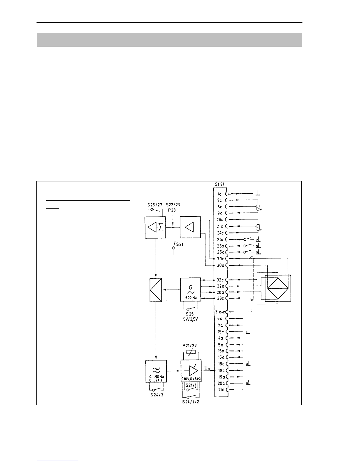
Notes for the diagram on the
right
S21:
calibration – measuring – zero
S22/23:
zero balancing (coarse)
S24/1+2:
MR1 fine balancing
internal/external
S24/3:
switch for measuring frequency
range 60Hz to 2Hz
S24/4:
MR changeover from MR1 to
MR2
S25:
switching the bridge excitation
voltage
S26/27:
setting of measuring range
(coarse)
P21/22:
fine balancing of MR
P23:
zero balancing (fine)
Cal. +1mV/V
zero
MR1
fine balancing
external
5kΩ
50kΩ
zero balancing
external
zero
calibr.
MR1–2
wh
gy
bk
bu
gn
14.5...15.5V <50mA
14.5...15.5V <50mA
–
+ 9V...+35V
(opt. DC/DC converter)
U
B
+14.5...+15.5V
UB –14.5...–15.5V
U
a
10V >5kOhm
option Ia 20mA
2.33V
ss
synchr.-voltage
or synchr. input
+
–
Fig. 1.1: Block diagram
Page 9
9
ME 30
2 Electrical Connection
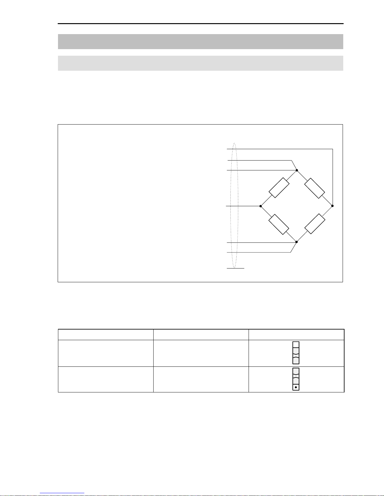
2.1 Transducer Connection
Strain gauge transducers are connected by means of 6-wire circuits.
With transducers in 4-wire technology the sensing leads are not needed. In
this case the contacts 32a+c and 28a+c on the connector must be linked.
screen pins 31a+c. . . . . . . . . . . . . . . . . .
rd
gy
bk
wh
bu
gn
ye
measuring signal (–) pin 30a. . . . . .
sensing line to 32a (–) pin 32c. . . . .
bridge supply voltage (–) pin 32a. .
measuring signal (+) pin 30c. . . . . .
bridge supply voltage (+) pin 28a. .
sensing line to 28c (+) pin 28c. . . . .
contact
(alternatively 29a+c)
Fig. 2.1: Bridge connection
The required bridge excitation voltage set by the factory is 5V(symmetrical
about ground). It can be switched to 2.5V by switch S25.
U
B
Bridge resistance Switch S25
2.5V R
B
≥60...4000Ω
5V
(ex-works settings)
R
B
≥110...4000Ω
The safety barriers SD01 must be wired into the connecting lines (see chapter 5.4) for transducers in EEx(i) design.
Page 10

10
ME 30
2.2 Supply Voltage
a) stabilized double-pole supply voltage
+14.5...+15.5V (max.70mA) . . . . . . . . . . .
–14.5...–15.5V (max.65mA) . . . . . . . . . . .
operating voltage zero . . . . . . . . . . . . . . .
The ripple on the supply voltage should not exceed 0.1V peak-to–peak. The
supply connections are internally protected against reverse polarity. Single
sided connection of the supply voltage should be avoided. The supply voltage
should be kept as low as possible within the permissible range of
±15.6...±25V in order to maintain the dissipation at a low value.
b) unstabilized double-pole supply voltage
If a stabilized voltage is not available, the amplifier can be operated by means
of a stabilizer(unstabilized supply) or a DC-DC converter (single-pole supply,
battery) (see chapter 5.1 and 5.2).
2.3 Output
output voltage: ±10V; RL ≥5 kΩ . . . . . . . .
operating voltage zero . . . . . . . . . . . . . . .
The output is provided for the connection of a display and/or recorders.
A current output is possible optionally (see chapter 5.3).
2.4 Supply Voltage for Additional Units
Stabilized voltages are available for current supply of additional function units.
+14.5V...+15.5V ; <50mA . . . . . . . . . . . . .
–14.5V...–15.5V ; <50mA . . . . . . . . . . . . .
operating voltage zero . . . . . . . . . . . . . . .
pin15a
pin16a
pin19c
+
pin18c
pin 20a
±
+
pin6c
pin 7a
pin15c
–
–
Page 11

11
ME 30
2.5 Pin Assignment
64-pin right angle plug
1c housing
2c not occupied
3c not occupied
4c not occupied
5c not occupied
6c output U
add.
=+14.5...+15.5V; <50mA
7c MR1 external fine balance (R=5kOhm)
8c MR1 external fine balance. tap
9c MR1 external fine balance (R=5kOhm)
10c not occupied
11c Synchronization
12c not occupied
13c not occupied
14c not occupied
15c operating voltage zero
16c not occupied
17c not occupied
18c output U
A
=±10V; R>5kOhm
19c operating voltage zero
20c not occupied
21c external zero balancing tap
22c not occupied
23c not occupied
24c external zero balancing
25c external switching from MR1 to MR2
26c external zero balancing
27c not occupied
28c sensing line (gn)
29c operating voltage zero
30c measuring signal (wh)
31c operating voltage zero (ye)
32c sensing line (gy)
St 21
1a not occupied
2a not occupied
3a not occupied
4a DC-DC converter positive pole
5a DC-DC converter negative pole
6a not occupied
7a output
U
add.
=–14.5...–15.5V; <50mA
8a not occupied
9a not occupied
10a not occupied
11a not occupied
12a not occupied
13a internally connected
14a internally connected
15a supply voltage
+14.5...+15.5V (standard)
16a supply voltage
–14.5...–15.5V (standard)
17a not occupied
18a not occupied
19a current output with EM002
20a operating voltage zero
21a zero function, external
22a not occupied
23a not occupied
24a not occupied
25a calibration function, external
26a not occupied
27a not occupied
28a bridge supply voltage (bu)
29a operating voltage zero
30a measuring signal (rd)
31a operating voltage zero (ye)
32a bridge supply voltage (bl)
Page 12

12
ME 30
3 Putting into Operation
If the factory settings, such as the measuring range or zero balance are retained, the operation is limited to setting the zero point and the measuring
ranges.
3.1 Select Measuring Range
With the factory setting
measuring range 1
(±2mV/V) is always switched on.
Measuring range 2 (calibration at ±0.2mV/V) can be selected either internally
via DIP switch 24/4 or externally by closing a single-pole change-over switch
to pin 25c against operating voltage zero (see chapter 4.2).
3.2 Bridge Zero Balancing
Carry out
bridge zero balancing
by means of the screwdriver potentiometers
P23 (fine) and switches S22 (coarse) and S23 (polarity). (See also chapter
4.4).
3.3 MR Fine Adjustment
The fine adjustment of the measuring range is made seperately for both
ranges by means of the screwdriver potentiometers P21 (measuring range 1)
and P22(measuring range 2). The potentiometers in the front panel permit
corrections of approx. 35% (related to the set measuring range). As far as
measuring range 1 is concerned, the fine adjustment is also possible via an
external potentiometer (for this see chapter 4.3).
Attention: P22 must not be altered in order not to detune the manufacturer’s
setting (MR2 ±0.2mV/V). (see chapter 4.5)
Page 13

13
ME 30
P21
P22
ME30
S21
P23
S22
S23
Fig. 3.1: Front view ME30
Page 14

14
ME 30
4 Individual Settings
Various ex-works settings on the measuring amplifier card can be altered.
Adaptations, which are of no problem, can be carried out by means of the DIP
switch on the board or also by externally wired switching elements. If requested with the order, they can be carried out by the manufacturer.
4.1 Operational Setting
Zero Measure Calibrate
S21
or connect pin 21a to pin 15c
or connect pin 25a to pin 15c
Switch
The transducer signal is switched off in the ”Zero” function, so that the ”Zero
Value” of the amplifier is applied to the output. This function enables amplifiers
to be replaced in measuring chain without the need for rebalancing the bridge
with the unloaded transducer. All that is required is that the amplifier balance
values are noted and then this value is set, if necessary, with P23, S22 and
S23.
4.2 Setting the Measuring Range
Measuring range 1 is get ex-works. Measuring range 2 can be activated by
switching DIP switch S24/4 or by external switching.
Measuring Range S 24/4 Externally
MR 1 = ±2mV/V
(ex-works setting)
–
MR 2 = ±0.2mV/V
from MR1 to MR2;
connect 25c and 15c
Any alteration to the measuring ranges between ±0.2mV/V and ±4mV/V with
U
B
= 5V (resp. ±0.4mV/V and ±8mV/V with UB = 2.5V) can be made by
means of the DIP switches S26 and S27. For fine balancing see 3.3.
Page 15

15
ME 30
UB = 5V MR1:S26 ; MR2:S27 ex-works sett.
Meas. range (mV/V) 1 2 3 4 5 6 7 8
0.17 0.24. . x o o o o o x o MR 2 ±0.2mV/V
0.22 0.32. . x o o o o o o x
0.30 0.42. . o x o o o o x o
0.39 0.55. . o x o o o o o x
0.52 0.73. . o o x o o o x o
0.68 0.97. . o o x o o o o x
0.90 1.28. . o o o x o o x o
1.18 1.69. . o o o x o o o x
1.56 2.23. . o o o o x o x o MR 1 ±2mV/V
2.07 2.94. . o o o o x o o x
2.73 3.88. . o o o o o x x o
3.61 5.13. . o o o o o x o x
o = open, x = closed
4.3 External Fine Balancing of the MR1
Connections:
potentiometer pin 9c. . . . . . . . . . . . .
wiper pin 8c. . . . . . . . . . . . . . . . . . . .
potentiometer finish pin 7c. . . . . . . .
An external 5kΩ potentiometer can be connected for fine adjustment of the
range. This will enable about 35% correction of the selected range.
R=5kΩ
Page 16

16
ME 30
4.4 Bridge Fine Balancing
a) Coarse Balancing
The 16-stage switch S22 is used for the coarse balancing carried out from the
front panel; the polarity of the balancing direction can be chosen via switch
S23. The overall balancing range is approximatly ±2mV/V.
b) Fine Balancing
The potentiometer P23 is used for the fine balancing (±0.08mV/V).
c) External Zero Balancing
A balance range of ±0.12mV/V set by the manufacturer can be passed with
an externally connected potentiometer of 50 kΩ
Pin assignment:
potentiometer pin 26c. . . . . . . . . . . . .
wiper pin 21c. . . . . . . . . . . . . . . . . . . .
potentiometer finish pin 24c. . . . . . . .
4.5 Calibration signal
Switching switch S21 to the right (calibration) detunes the amplifier by a defined amount (=+1mV/V). The measuring range can be adjusted without having to load the connected transducer respectively. The voltage at the amplifier
output which is equal to the calibration signal is added to an available voltage,
if any (additive calibration signal)
R=50kΩ
Page 17

17
ME 30
4.6 Measuring Frequency Range / Cut-off Frequency f
co
The Butterworth low pass of the amplifier has been set to 0...60Hz (–1dB) by
the manufacturer. It can be readjusted by switching the DIP switch S24/3 to
0...2Hz (–1dB).
Measuring frequency range S 24/3
0...60Hz (–1dB); (ex-works setting)
fco = 80Hz (–3dB)
0...2Hz (–1dB);
fco = 2.5Hz (–3dB)
4.7 Synchronization
When operating several ME30 amplifiers (in a common housing), one of them
has to be switched as the master the carrier frequency of which supplies the
clock pulses, the others are to be switched as slave. Pins 11c of all amplifiers
have to be joined for synchronization. The master amplifier is selected by
switch S28.
Synchronization Switch S28
Slave amplifier (ex-works setting)
Master amplifier
Page 18

18
ME 30
5 Options
5.1 Stabilized Power Supply
The module KM001 can be used if the amplifier is connected to a symmetrical unregulated supply voltage of ± 15.6...25.0V. The module supplies the two
stabilized supply voltages internally to the amplifier.When installing the module KM001, attention should be paid to the marking (bridge 3 and bridge 4 on
pin 1 and 2).
Pin assignment:
positive pole pin 15a. . . . . . . . . . . . . .
negative pole pin 16a. . . . . . . . . . . . .
supply zero pin 19c. . . . . . . . . . . . . . .
5.2 DC-DC Converter
The manufacturer can mount a DC-DC converter onto the board for the oper-
ation of a single-pole supply voltage (battery). The voltage converter is suitable for operation on +9...+35V (unstabilized).
Pin assignment:
positive pole pin 4a. . . . . . . . . . . . . .
negative pole pin 5a. . . . . . . . . . . . .
The DC-DC converter decouples the internal operating voltages from the supply voltage.
When using the modules KM001 resp. a DC-DC converter attention has to
be paid to the jumpers BR3 and BR4 which are re-configured.
ex-works setting:
1 2 3
BR3
BR4
I
I
With module KM001
resp. DC-DC converter
1 2 3
BR3
BR4
I
I
Page 19

19
ME 30
5.3 Current Output Module
The module EM002 can be installed to obtain a current output.
The pin assignment is as follows:
output current pin 19a. . . . . . . . . . . . .
supply zero pin 20a. . . . . . . . . . . . . . .
The power range is switched by the DIP switch 24/5.
Output current source S24/5
+4...+20 mA
+20 mA (ex-works setting)
When using an EM002, current and voltage outputs are not aligned to each
other. The required fine calibration can be carried out from the front panel (as
described in chapter 3)
5.4 Safety Barriers for use in Hazardous Areas
For transducer operation in potentially explosive atmospheres the safety barriers SD01 are used conforming to the protection classes (EEx ib IIC) according to VDE0171, EN 50 014 and EN 50 020 (see data sheet).
5.5 Additional Units
The following additional cards are available for the measuring amplifier ME30:
– automatic zeroing unit NE02
– peak / last value memory SE03
– limit switch GE04
Page 20

20
ME 30
6 General Notes
6.1 Disturbances
Certain regulations concerning electrical installation have to be observed in
plants with strongly disturbed supply mains systems. The most important
points are listed up in the HBM leaflet ”Hints for connection/disturbances”. An
extensive summary is given in the installation regulations VDI/VDE 3551. The
extent of certain measures to be taken depends on the specific applications.
Page 21

21
ME 30
7 Technical Data
Type ME30
Carrier frequency Hz 600±0.5%
Bridge excitation voltage V 2.5±2% 5±0.2%
Transducers which can be connected
strain gauge transducers (full bridge) W 60...4000 110...4000
maximum cable length m 500
Number of measuring ranges 2
measuring ranges, adjustable in 12 steps mV/V 0.4...8 0.2...4
continuous fine adjustment; % 35
ex-works setting: Measuring Range 1 mV/V ±2
Measuring Range 2 mV/V ±0.2
Calibration signal mV/V +1±0.1%
Bridge balance range
coarse balance, adjustable in 16 steps and
polarity
mV/V ±2
fine balance, with screwdriver potentiometer mV/V ±0.08
Measuring frequency (Butterworth low pass 3rd order;
switchable)
at –1dB Hz 0...2 0...60
at –3dB Hz 2.5 80
phase delay ms 135 4.8
rise time ms 170 7
surge voltage overshoot % <10 <10
residual carrier % <0.1 <0.2; typ. 0.1
Input (symmetrical)
input resistance MΩ
par.
pF
>10
470
perm. common-mode voltage V 12 (peak-to-peak) ; (±6V)
common-mode rejection (>50 dB) Hz 0...600
Output (asymetrical)
nominal voltage V ±10
permissible load resistance kΩ >5
internal resistance W <5
Page 22

22
ME 30
7 Technical Data (Continuation)
Noise, referred to input
µV/V <0.2 (peak-to-peak); typ.0.1
Linearity deviation
related to nominal voltage
% <0.02; typ. 0.01
Temperature influence
per 10K in nominal temperature range
on measuring sensitivity % <0.1; typ. 0.05
on zero point at amplifier output
in MR 2mV/V at UB=5V (4x350Ω) mV <4, resp.
in MR 0.2mV/V at UB=5V mV <13; additionally
<0.05% of the tare value
suppressed with the R compensation
Long term drift over 48h (after 1h warm-up) µV/V <0.05
Nominal temperature range °C –10...+60
Operating temperature range °C –20...+60
Storage temperature range °C –25...+70
Stabilized Voltage
for the operation of additional units V ±15
max. power consumption mA <50
Supply current standard;
stab.
KM001 DC-DC
converter
Supply voltage V 14.5... 15.5 15.6...
25
+9...+35
max. current consumption (without
additional units)
mA +70/–65 <+80/<–70 340...140
influence of supply voltage
for changes in the relevant range
the measuring sensitivity % <0.8 <0.02 <0.02
the zero point µV/V <0.1 <0.1 <0.1
Output current, with option EM002 mA 20 acc. +4...+20
permissible connection resistance W 0...500
internal resistance kΩ >100
current consumption
with standard and KM001 add. mA < + 30
with DC-DC converter mA 75...25
linearity deviation related to nominal current % <0.05
Page 23

23
ME 30
8 Component Layout
Page 24

24
ME 30
9 Copy of Declaration of Conformity
Page 25

25
ME 30
Page 26

26
ME 30
Page 27

27
ME 30
Page 28

HOTTINGER BALDWIN MESSTECHNIK
HBM Mess- und Systemtechnik GmbH
Postfach 10 01 51, D-64201 Darmstadt
Im Tiefen See 45, D-64293 Darmstadt
Tel.: +49/ 61 51/ 8 03-0; Fax: +49/ 61 51/ 89 48 96;
www.hbm.de
e–mail: TSC@hottinger–baldwin.com
Modifications reserved.
All details describe our products in
general form only.
They are not to be understood as express
warranty and do not constitute any liability
whatsoever.
IM–D 09.99–POD
 Loading...