

Page 1
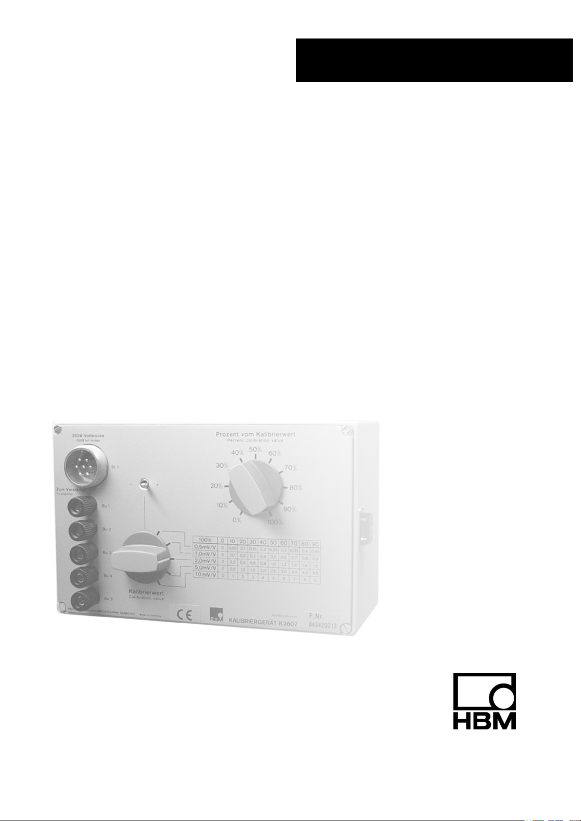
Operating manual
Bedienungsanleitung
Kalibriergerät
Calibration instrument
K3607
A0833-3.0 en/de
Page 2

English Page 3 − 12. . . . . . . . . . . . . . . . . . . . . . . . . . . . . . . . . . . . . . . . . . . . . . . . .
Deutsch Seite 13 − 22. . . . . . . . . . . . . . . . . . . . . . . . . . . . . . . . . . . . . . . . . . . . . . .
Page 3

K3607
Contents Page. . . . . . . . . . . . . . . . . . . . . . . . . . . . . . . . . . . . . . . . . . . . . . . . . . . . .
Safety instructions 5 . . . . . . . . . . . . . . . . . . . . . . . . . . . . . . . . . . . . . . . . . . . . .
8 Fields of application 8 . . . . . . . . . . . . . . . . . . . . . . . . . . . . . . . . . . . . . . . .
9 Connections 8 . . . . . . . . . . . . . . . . . . . . . . . . . . . . . . . . . . . . . . . . . . . . . . . .
10 Calibrating the measurement chain 9 . . . . . . . . . . . . . . . . . . . . . . . . . . .
11 Works calibration of the K3607 10 . . . . . . . . . . . . . . . . . . . . . . . . . . . . . . .
12 Effect of cable resistance 10 . . . . . . . . . . . . . . . . . . . . . . . . . . . . . . . . . . . .
13 Pin assignment 11 . . . . . . . . . . . . . . . . . . . . . . . . . . . . . . . . . . . . . . . . . . . . .
14 Specifications 12 . . . . . . . . . . . . . . . . . . . . . . . . . . . . . . . . . . . . . . . . . . . . . .
3
HBMA0833-3.0 en/de
Page 4

4
K3607
HBM A0833-3.0 en/de
Page 5

K3607
5
Safety instructions
Appropriate use
The K3607 calibration instrument is to be used exclusively for measurement
tasks and directly related control tasks. Use for any purpose other than the
above shall be deemed to be not in accordance with the regulations.
In the interests of safety, the instrument should only be operated as described
in the Operating Manual. It is also essential to comply with the legal and
safety requirements for the application concerned during use. The same
applies to the use of accessories.
General dangers of failing to follow the safety instructions
The calibration instrument is a state of the art unit and as such is fail-safe.
The device may give rise to further dangers if it is inappropriately installed and
operated by untrained personnel.
Any person instructed to carry out installation, commissioning, maintenance or
repair of the device must have read and understood the Operating Manual
and in particular the technical safety instructions.
Conditions on site
Protect the device from direct contact with water.
Maintenance and cleaning
The calibration instrument is maintenance free. Please note the following
points when cleaning the housing:
− Before cleaning, disconnect the device from the power supply.
− Clean the housing with a soft, slightly damp (not wet!) cloth. You should
never use solvent, since this could damage the labelling on the front
panel.
− When cleaning, ensure that no liquid gets into the device or connections.
Remaining dangers
The scope of supply and list of components provided with the K3607 cover
only part of the scope of measurement technique. In addition, equipment
planners, installers and operators should plan, implement and respond to the
safety engineering considerations of measurement technique in such a way
as to minimize remaining dangers. Prevailing regulations must be complied
with at all times. There must be reference to the remaining dangers connected
with measurement technique.
A0833-3.0 en/de HBM
Page 6
6
Any risk of remaining dangers when working with the K3607 is pointed out in
this introduction by means of the following symbols:
K3607
Symbol:
Meaning: Dangerous situation
Warns of a potentially dangerous situation in which failure to comply with
safety requirements can result in death or serious physical injury.
Symbol:
Meaning: Potentially dangerous situation
Warns of a potentially dangerous situation in which failure to comply with
safety requirements could result in damage to property or some form of
physical injury.
Symbol:
Means that important information about the product or its handling is being
given.
WARNING
CAUTION
NOTE
Symbol:
Meaning: CE mark
The CE mark enables the manufacturer to guarantee that the product
complies with the requirements of the relevant EC directives (the Declaration
of Conformity can be found at http://www.hbm.com/HBMdoc).
HBM A0833-3.0 en/de
Page 7

K3607
7
Conversions and modifications
The device must not be modified from the design or safety engineering point
of view except with our express agreement. Any modification shall exclude all
liability on our part for any resulting damage.
In particular, any repair or soldering work on motherboards is prohibited.
When exchanging complete modules, use only original parts from HBM.
Qualified personnel
This instrument is only to be installed and used by qualified personnel strictly
in accordance with the technical data and with the safety rules and regulations
which follow. It is also essential to comply with the legal and safety
requirements for the application concerned during use. The same applies to
the use of accessories.
Qualified personnel means persons entrusted with the installation, assembly,
commissioning and operation of the product who possess the appropriate
qualifications for their function.
Maintenance and repair work on an open device with the power on must only
be carried out by trained personnel who are aware of the dangers involved.
A0833-3.0 en/de HBM
Page 8
8
K3607
1 Fields of application
The K 3607 calibration instrument can be used to calibrate measuring
amplifiers or measurement chains without imposing a mechanical quantity on
the SG transducers belonging to the measurement chain.
For this purpose the calibration instrument is equipped with a high-precision
resistance network in star configuration, designed to simulate 350-Ω SG
full-bridge transducers.
The extremely low self-capacitance and self-inductance of the inbuilt precision
resistors place the calibration instrument in accuracy class 0.025.
When an appropriate measuring amplifier is used, the calibration instrument
can be operated in six-wire circuit for balancing the ohmic and capacitive
effects of long measurement cables.
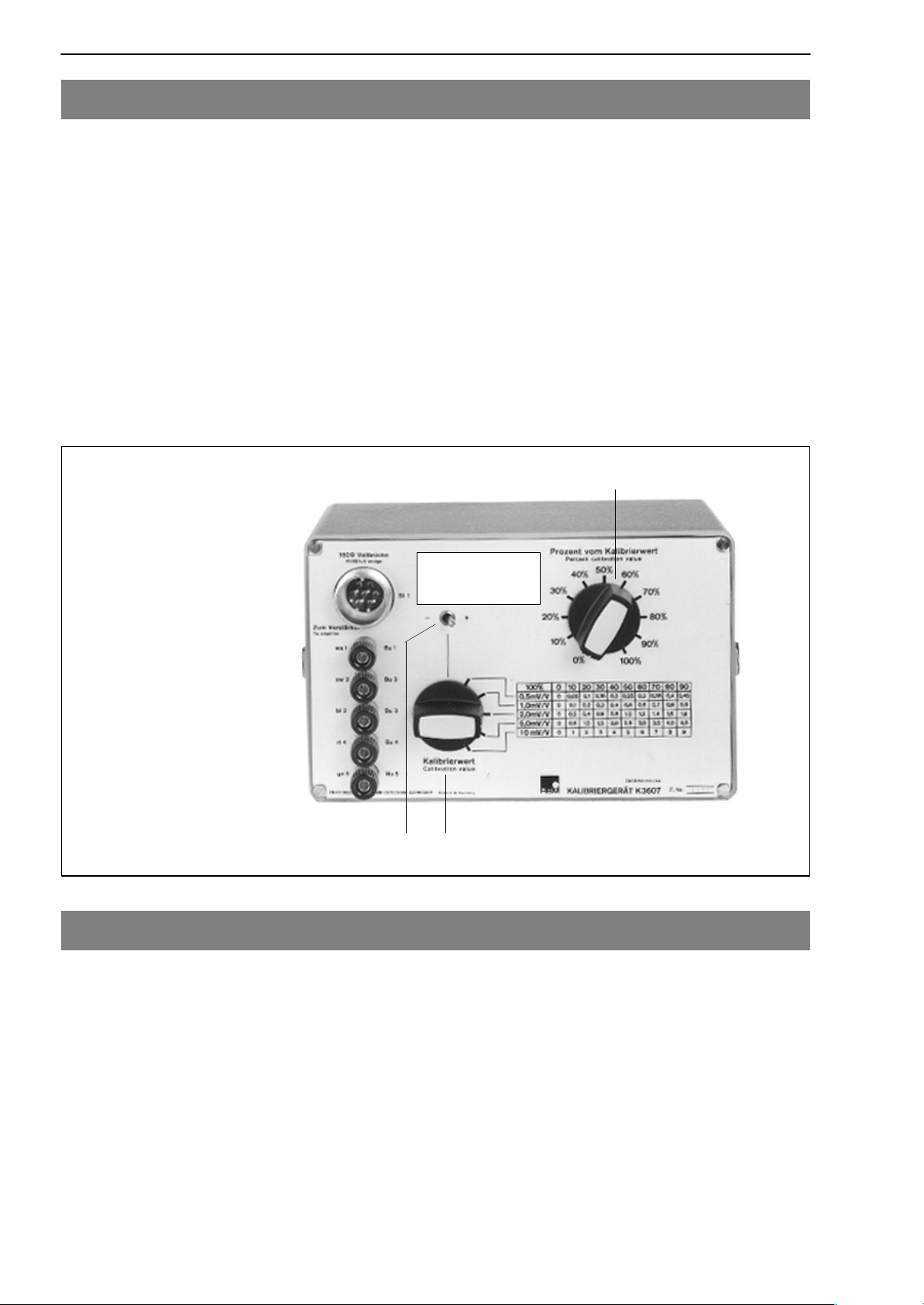
K 3607 front panel
S1 = polarity switch
S2 = calibration step switch
S3 = calibration value switch
Calibration valid at
end of cable (Kab.
S1
S3
S2
0238A−3).
2 Connections
The connector cable between the calibration instrument and the measuring
amplifier is connected either to the 7-pin Amphenol connector MS 3102
A16S-1P (St1) or to the 5-pin S3 (Bu 1 . . . Bu 5).
The contact assignment is shown in Fig. 6.1. The Amphenol connection is
provided for a six-wire circuit. If the intention is to connect a six-wire circuit to
the pin terminals, connections C and F on the measuring amplifier must both
be connected to Bu3 on the calibration instrument, and connections B and G
must both be connected to Bu2.
HBM A0833-3.0 en/de
Page 9

K3607
3 Calibrating the measurement chain
• Connect the calibration instrument to the measurement chain you wish to
calibrate in place of the 350-Ω SG transducer. If there is an extension cable
on the measuring amplifier, leave it in place in order to capture the ohmic
and capacitive cable effects.
• Use S1 to preselect the desired polarity of the measurement signal.
• Set S2 (calibration step switch) to zero.
• If necessary switch the measuring amplifier to full bridge (K 3607 operates
as a full bridge).
• Balance the measuring amplifier and subsequent instruments to zero in
accordance with their operating manuals and if necessary carry out
capacitance adjustment.
9
• Use the calibration value switch S3 and the calibration step switch S2 to
set the desired calibration signal:
Calibration value in
mV/V
0 10 20 30 40 50 60 70 80 90 100
0.5 0 0.05 0.1 0.15 0.2 0.25 0.3 0.35 0.4 0.45 0.5
1.0 0 0.1 0.2 0.3 0.4 0.5 0.6 0.7 0.8 0.9 1.0
2.0 0 0.2 0.4 0.6 0.8 1.0 1.2 1.4 1.6 1.8 2.0
5.0 0 0.5 1.0 1.5 2.0 2.5 3.0 3.5 4.0 4.5 5.0
10.0 0 1.0 2.0 3.0 4.0 5.0 6.0 7.0 8.0 9.0 10.0
Tab 3.1: Calibration signal in mV/V as a function of the switch settings on the K3607
Calibration step*) in %
• Set the measuring amplifier to the desired output signal in accordance with
its operating manual. In principle the measuring amplifier should be
calibrated in the measuring range you intend to use for measurement. If the
measuring range of the amplifier is changed, the switching error needs to
be taken into consideration.
*)
Effect of the calibration step switch (S2):
The grading error for the percentage steps as set out in the specifications will be maintained for every
step if the internal resistance Ri of the bridge excitation source plus cable is v 1Ω. For an internal
resistance Ri v 4Ω the error in the calibration steps is kept at between 0 and 50 %.
For a six-wire circuit the tolerances are maintained if the excitation voltage to the K 3607 is readjusted
precisely enough.
A0833-3.0 en/de HBM
Page 10

10
K3607
4 Works calibration of the K3607
The K 3607 is calibrated in the factory under the following conditions:
o
− Ambient temperature: + 23
C
− Connector cable:
Kab 0238A−3 (included in the list of components supplied), cable length =
3 meters
Cross-section of each bridge excitation wire 1.5mm
2
− Internal excitation voltage resistance: v1Ω
5 Effect of cable resistance
The cable effect for KAB0238A-3 cable is calibrated in at the factory. This
applies to four- and six-wire circuit at the end of the 3-meter long cable.
On subsequent connection in four-wire circuit, the output signal is reduced by
the K factor due to the resistance of the excitation wires.
The K factor is calcultated as follows:
Bridge resistance)
The resistance value of an excitation wire is used for the r term. In the case of
KAB0238A-3 cable this resistance r = 0.0118 Ω. According to the formula (1)
this gives a value of 0.99993 for the K factor. This means an absolute
calibration error of 0.007% if KAB0238A-3 is not used.
A switching step error also occurs. Depending on the position of switch S2 the
internal resistance of the K 3607 alters slightly, as does the effective excitation
voltage due to the cable resistance r.
The grading error of the percentage steps increases by some 0.02% at 10 Ω
of cable conductor resistance.
When connecting a six-wire circuit the cable effect is corrected and the K
factor = 1. No additional grading error occurs (internal excitation voltage
resistance < 1 Ω).
If KAB0238A-3 cable is not used, an absolute calibration error of the
corresponding size occurs. This means the output signal is increased by a
factor of K = 1.00007.
HBM A0833-3.0 en/de
Page 11

K3607
6 Pin assignment
Connection to 7-pin Amphenol connector St1
11
MS3102A 16S−1P
St1
MS3102A 16S−1P
St1
MS3106A 16S−1S
MS3106A 16S−1P
A
To the amplifier input
B
C
D
Sensor circuit to the
E
F
measuring amplifier,
G
six-wire circuit only
Cable to measuring amplifier:
Amphenol connector − Amphenol
connector
MS3106A 16S−1S Sub-D 15p
8
5
6
15
Hsg.
13
12
To the amplifier input
Sensor circuit to the
measuring amplifier,
six-wire circuit only
Cable to measuring amplifier:
Amphenol connector − sub-D
connector
Connecting to pin terminals
MS3102A 16S−1P
St1
MS3106A 16S−1P
A
B
C
D
E
Sensor circuit to the
F
measuring amplifier,
G
six-wire circuit only
To the amplifier input
Cable to measuring amplifier:
Pigtails − Amphenol connector
Fig. 6.1: General pin assignment
A0833-3.0 en/de HBM
Page 12

12
K3607
7 Specifications
Type K3607
Accuracy class 0.025
Calibration steps
5 range steps
mV/V
11 percentage steps within the range step concerned
%
Polarity switch Choice of positive1) or negative
Grading error of range steps
relative to the full-scale value concerned
% t"0.025
Grading error of percentage steps
relative to the full-scale value concerned
% t"0.01
Calibration tolerance of full-scale value (absolute)
at 2mV/V calibration value setting (100%)
(at reference temperature, 3 meters of connection cable
2)
)
% t"0.02
Temperature effect of absolute calibration per
10K
in the operating temperature range
in the nominal temperature range
Reference temperature
Nominal temperature range
Operating temperature range
Storage temperature range
%
%
o
C +23
o
C +10...+50
o
C +10...+60
o
C −25...+70
Frequency range of the excitation voltage Hz (DC)...5000Hz
Nominal range of the excitation voltage V 0.5...12
Maximum permissible excitation voltage V 18
Weight kg 1
Dimensions (w x h x d) mm 200 x 110 x 120
1)
In this case ”positive” means a reduction in bridge branch resistance between Bu 1 and Bu 3 (between A
and C on the Amphenol connector)
2)
Kab 0238A−3
3)
At reduced precision up to 50 kHz (accuracy class 0.5)
0.5; 1; 2; 5; 10
0; 10; 20...100
output signals
t0.03
t0.01
3)
HBM A0833-3.0 en/de
Page 13

K3607
13
Inhalt Seite
Sicherheitshinweise 15 . . . . . . . . . . . . . . . . . . . . . . . . . . . . . . . . . . . . . . . . . . . .
8 Anwendungsbereiche 18 . . . . . . . . . . . . . . . . . . . . . . . . . . . . . . . . . . . . . . .
9 Anschließen 18 . . . . . . . . . . . . . . . . . . . . . . . . . . . . . . . . . . . . . . . . . . . . . . . .
10 Kalibrieren der Messkette 19 . . . . . . . . . . . . . . . . . . . . . . . . . . . . . . . . . . . .
11 Werkskalibrierung des K3607 20 . . . . . . . . . . . . . . . . . . . . . . . . . . . . . . . .
12 Einfluss des Kabelwiderstandes 20 . . . . . . . . . . . . . . . . . . . . . . . . . . . . .
13 Anschlussbelegung 21 . . . . . . . . . . . . . . . . . . . . . . . . . . . . . . . . . . . . . . . . .
14 Technische Daten 22 . . . . . . . . . . . . . . . . . . . . . . . . . . . . . . . . . . . . . . . . . . .
HBMA0833-3.0 en/de
Page 14

14
K3607
HBM A0833-3.0 en/de
Page 15

K3607
15
Sicherheitshinweise
Bestimmungsgemäße Verwendung
Das Kalibriergerät K3607 ist ausschließlich für Messaufgaben und direkt damit verbundene Steuerungsaufgaben zu verwenden. Jeder darüber hinausgehende Gebrauch gilt als nicht bestimmungsgemäß.
Zur Gewährleistung eines sicheren Betriebes darf das Gerät nur nach den
Angaben in der Bedienungsanleitung betrieben werden. Bei der Verwendung
sind zusätzlich die für den jeweiligen Anwendungsfall erforderlichen Rechtsund Sicherheitsvorschriften zu beachten. Sinngemäß gilt dies auch bei
Verwendung von Zubehör.
Allgemeine Gefahren bei Nichtbeachten der Sicherheitshinweise
Das Kalibriergerät entspricht dem Stand der Technik und ist betriebssicher.
Von dem Gerät können Restgefahren ausgehen, wenn es von ungeschultem
Personal unsachgemäß eingesetzt und bedient wird.
Jede Person, die mit Aufstellung, Inbetriebnahme, Wartung oder Reparatur
des Gerätes beauftragt ist, muss die Bedienungsanleitung und insbesondere
die sicherheitstechnischen Hinweise gelesen und verstanden haben.
Bedingungen am Aufstellungsort
Schützen Sie das Gerät vor direktem Kontakt mit Wasser.
Wartung und Reinigung
Das Kalibriergerät ist wartungsfrei. Beachten Sie bei der Reinigung des Gehäuses folgende Punkte:
− Trennen Sie vor der Reinigung die Verbindung zur Stromversorgung.
− Reinigen Sie das Gehäuse mit einem weichen und leicht angefeuchteten
(nicht nassen!) Tuch. Verwenden Sie auf keinen Fall Lösungsmittel, da
diese die Frontplattenbeschriftung angreifen könnte.
− Achten Sie beim Reinigen darauf, dass keine Flüssigkeit in das Gerät oder
an die Anschlüsse gelangt.
Restgefahren
Der Leistungs- und Lieferumfang des K3607 deckt nur einen Teilbereich der
Messtechnik ab. Sicherheitstechnische Belange der Messtechnik sind zusätzlich vom Anlagenplaner/Ausrüster/Betreiber so zu planen, zu realisieren und
zu verantworten, dass Restgefahren minimiert werden. Jeweils existierende
Vorschriften sind zu beachten. Auf Restgefahren im Zusammenhang mit der
Messtechnik ist hinzuweisen.
A0833-3.0 en/de
HBM
Page 16

16
Sollten Restgefahren beim Arbeiten mit dem K3607 auftreten, wird in dieser
Anleitung mit folgenden Symbolen darauf hingewiesen:
K3607
Symbol:
Bedeutung: Gefährliche Situation
Weist auf eine mögliche gefährliche Situation hin, die − wenn die Sicherheits-
bestimmungen nicht beachtet werden − Tod oder schwere Körperverletzung
zur Folge haben kann.
Symbol:
Bedeutung: Möglicherweise gefährliche Situation
Weist auf eine mögliche gefährliche Situation hin, die − wenn die Sicherheitsbestimmungen nicht beachtet werden − Sachschaden, leichte oder mittlere
Körperverletzung zur Folge haben könnte.
Symbol:
WARNUNG
ACHTUNG
HINWEIS
Weist darauf hin, dass wichtige Informationen über das Produkt oder über die
Handhabung des Produktes gegeben werden.
Symbol:
Bedeutung: CE-Kennzeichnung
Mit der CE-Kennzeichnung garantiert der Hersteller, dass sein Produkt den
Anforderungen der relevanten EG-Richtlinien entspricht (die Konformitätserklärung finden Sie unter http://www.hbm.com/HBMdoc).
HBM A0833-3.0 en/de
Page 17

K3607
17
Umbauten und Veränderungen
Das Gerät darf ohne unsere ausdrückliche Zustimmung weder konstruktiv
noch sicherheitstechnisch verändert werden. Jede Veränderung schließt eine
Haftung unsererseits für daraus resultierende Schäden aus.
Insbesondere sind jegliche Reparaturen, Lötarbeiten an den Platinen untersagt. Bei Austausch gesamter Baugruppen sind nur Originalteile von HBM zu
verwenden.
Qualifiziertes Personal
Dieses Gerät ist nur von qualifiziertem Personal ausschließlich entsprechend
der technischen Daten in Zusammenhang mit den nachstehend aufgeführten
Sicherheitsbestimmungen und Vorschriften einzusetzen bzw. zu verwenden.
Bei der Verwendung sind zusätzlich die für den jeweiligen Anwendungsfall erforderlichen Rechts- und Sicherheitsvorschriften zu beachten. Sinngemäß gilt
dies auch bei Verwendung von Zubehör.
Qualifiziertes Personal sind Personen, die mit Aufstellung, Montage, Inbetriebsetzung und Betrieb des Produktes vertraut sind und die über die ihrer
Tätigkeit entsprechende Qualifikationen verfügen.
Wartungs- und Reparaturarbeiten am geöffneten Gerät unter Spannung dürfen nur von einer ausgebildeten Person durchgeführt werden, die sich der vorliegenden Gefahr bewusst ist.
A0833-3.0 en/de
HBM
Page 18

18
K3607
8 Anwendungsbereiche
Mit dem Kallbriergerät K 3607 können Messverstärker bzw. Messketten kalibriert werden, ohne dass der zur Messkette gehörende DMS-Aufnehmer mit
einer mechanischen Größe beaufschlagt wird.
Dazu ist das Kallbriergerät mit einem hochgenauen Widerstandsnetzwerk in
Sternschaltung ausgerüstet, welches zur Simulation von 350-Ω-DMS-Voll-
brückenaufnehmern ausgelegt ist.
Die extrem niedrigen Eigenkapazitäten und Eigeninduktivitäten der eingebauten Präzisions-Widerstände ermöglichen die Genauigkeitsklasse 0,025
des Kalibriergerätes.
Bei Verwendung eines entsprechenden Messverstärkers kann das Kalibriergerät, zum Ausgleich ohmscher und kapazitiver Einflüsse langer Messkabel,
in Sechsleiter-Schaltung betrieben werden.
Frontplatte K 3607
S1 = Polaritätsschalter
S2 = Kalibrierstufenschalter
S3 = Kalibrierwertschalter
Kalibrierung gültig
am Ende des Kabels
(Kab. 0238A−3).
S3
S1
S2
9 Anschließen
Das Verbindungskabel zwischen Kalibriergerät und Messverstärker wird entweder an den 7poligen Amphenolstecker MS 3102 A16S-1P (St1) oder an die
5 Polklemmen (Bu 1 . . . Bu 5) angeschlossen.
Die Kontaktbelegung ist aus Abb. 6.1 ersichtlich. Die Amphenolsteckerverbindung ist für eine Sechsleiter-Schaltung vorgesehen. Soll eine SechsleiterSchaltung an die Polklemmen angeschlossen werden, so sind die Anschlüsse
C und F des Messverstärkers gemeinsam an Bu3 und die Anschlüsse B und
G an Bu2 des Kalibriergerätes anzuschließen.
HBM A0833-3.0 en/de
Page 19

K3607
19
10 Kalibrieren der Messkette
• Kalibriergerät an Stelle des 350-Ω-DMS−Aufnehmers an die zu kali-
brierende Messkette anschließen. Eventuelle Verlängerungskabel am
Messverstärker belassen, um die ohmschen und kapazitiven Kabeleinflüsse zu erfassen.
• Mit S1 gewünschte Polarität des Messsignals vorwählen.
• S2 (Kalibrierstufenschalter) auf Null stellen.
• Messverstärker gegebenenfalls auf Vollbrücke schalten (K 3607 arbeitet
als Vollbrücke).
• Messverstärker und Nachfolgegeräte entsprechend deren Bedienungsan-
leitungen auf Null abgleichen und, falls notwendig, Kapazitätsabgleich
durchführen.
• Mit dem Kalibrierwertschalter S3 und Kalibrierstufenschalter S2 gewünsch-
tes Kalibriersignal einstellen:
Kalibrierwert in mV/V Kalibrierstufe*) in %
0 10 20 30 40 50 60 70 80 90 100
0,5 0 0,05 0,1 0,15 0,2 0,25 0,3 0,35 0,4 0,45 0,5
1,0 0 0,1 0,2 0,3 0,4 0,5 0,6 0,7 0,8 0,9 1,0
2,0 0 0,2 0,4 0,6 0,8 1,0 1,2 1,4 1,6 1,8 2,0
5,0 0 0,5 1,0 1,5 2,0 2,5 3,0 3,5 4,0 4,5 5,0
10,0 0 1,0 2,0 3,0 4,0 5,0 6,0 7,0 8,0 9,0 10,0
Tab 3.1: Kalibriersignal in mV/V in Abhängigkeit der Schaltereinstellungen am K3607
• Messverstärker gemäß seiner Bedienungsanleitung auf gewünschtes Aus-
gangssignal bringen. Grundsätzlich sollte der Messverstärker in dem Messbereich kalibriert werden, der für die Messung vorgesehen ist. Wird der
Messbereich des Messverstärkers umgeschaltet, ist der Umschaltfehler zu
berücksichtigen.
*)
Einfluss des Kalibrierstufenschalters (S2): Der in den technischen Daten angegebene Stufungsfehler der
Prozentstufen wird für alle Stufen eingehalten, wenn der Innenwiderstand Ri von Brückenspeisespan-
nungsquelle plus Kabel v 1Ω ist. Für den Innenwiderstand Ri v 4Ω wird der Fehler in den Kalibrierstufen 0 ... 50 % eingehalten. Bei Sechsleiter-Schaltung werden die Toleranzen eingehalten, wenn die Speisespannung am K 3607 entsprechend genau nachgeregelt wird.
A0833-3.0 en/de
HBM
Page 20

20
K3607
11 Werkskalibrierung des K3607
Die Kalibrierung des K 3607 erfolgt im Werk unter folgenden Bedingungen:
o
− Umgebungstemperatur: + 23
C
− Anschlusskabel:
Kabel Kab 0238A−3 (im Lieferumfang enthalten), Kabellänge = 3 m
Querschnitt je Brückenspeisespannungsader 1,5mm
2
− Innenwiderstand der Brückenspeisespannung: v1Ω
12 Einfluss des Kabelwiderstandes
Für das Kabel KAB0238A−3 ist der Kabeleinfluss werkseitig einkalibriert. Dies
gilt für Vier− und Sechsleiter-Schaltung am Ende des 3 m langen Kabels.
Beim nachfolgenden Anschluss in Vierleiter-Schaltung wird, bedingt durch
den Widerstand der Brückenspeisespannungsadern, das Ausgangssignal um
den Faktor K verkleinert.
Für r wird der Widerstandswert einer Brückenspeisespannungsader eingesetzt. Beim Kabel KAB0238A−3 beträgt dieser Widerstand r = 0,0118 Ω. Nach
Formel (1) ergibt sich für den Faktor K der Wert 0,99993. Dies bedeutet einen
absoluten Kalibrierfehler von 0,007% wenn KAB0238A−3 nicht verwendet
wird.
Zusätzlich tritt ein Schaltstufenfehler auf. Je nach Schalterstellung von S2
ändert sich geringfügig der Innenwiderstand des K 3607 und über den Kabelwiderstand r die effektive Brückenspeisespannung.
Der Stufungsfehler der Prozentstufen erhöht sich z.B. um 0,02% bei 10 Ω
Kabeladerwiderstand.
Beim Anschluss einer Sechsleiter-Schaltung wird der Kabeleinfluss ausgeregelt, der Faktor K = 1. Es tritt kein zusätzlicher Stufungsfehler auf (Innenwiderstand der Brückenspeisespannung < 1 Ω).
Wird das Kabel KAB0238A−3 nicht verwendet, tritt ein absoluter Kalibrierfehler in entsprechender Größe auf. Dies bedeutet eine Erhöhung des Ausgangssignals um den Faktor K = 1,00007.
HBM A0833-3.0 en/de
Page 21

K3607
13 Anschlussbelegung
Anschluss an 7poligen Amphenolstecker St1
21
MS3102A 16S−1P
St1
MS3102A 16S−1P
St1
MS3106A 16S−1S
MS3106A 16S−1P
A
zum Messverstärkerein-
B
C
gang
D
Fühlerleitung zum Mess-
E
F
verstärker, nur bei Sechs-
G
leiterschaltung
Kabel zum Messverstärker:
Amphenolstecker − Amphenolstecker
MS3106A 16S−1S D−Sub 15p
8
5
6
15
Geh.
13
12
zum Messverstärkereingang
Fühlerleitung zum Messverstärker, nur bei Sechsleiterschaltung
Kabel zum Messverstärker:
Amphenolstecker − D−Sub−Stecker
Anschluss an Polklemmen
Abb. 6.2: Allgemeine Anschlussbelegung
A0833-3.0 en/de
MS3102A 16S−1P
St1
Kabel zum Messverstärker:
freie Enden − Amphenolstecker
MS3106A 16S−1P
A
B
C
D
E
Fühlerleitung zum Mess-
F
verstärker, nur bei Sechs-
G
leiterschaltung
zum Messverstärkereingang
HBM
Page 22

22
K3607
14 Technische Daten
Typ K3607
Genauigkeitsklasse 0,025
Kalibrierstufen
5 Bereichsstufen
mV/V
11 Prozentstufen innerhalb der jeweiligen
Bereichsstufe
%
Polaritätsschalter wahlweise positive1) oder negative
Stufungsfehler der Bereichsstufen
bezogen auf den jeweiligen Bereichsendwert
% t"0,025
Stufungsfehler der Prozentstufen
bezogen auf den jeweiligen Bereichsendwert
% t"0,01
Kalibriertoleranz des Bereichsendwertes (absolut)
bei 2mV/V Kalibrierwerteinstellung (100%)
(bei Referenztemperatur, 3m Anschlusskabel
2)
% t"0,02
)
Temperatureinfluss der absoluten Kalibrierung
pro 10K
im Gebrauchstemperaturbereich
im Nenntemperaturbereich
Referenztemperatur
Nenntemperaturbereich
Gebrauchstemperaturbereich
Lagerungstemperaturbereich
%
%
o
C +23
o
C +10...+50
o
C +10...+60
o
C −25...+70
Frequenzbereich der Speisespannung Hz (DC)...5000Hz
Nennbereich der Speisespannung V 0,5...12
Maximal zulässige Speisespannung V 18
Gewicht kg 1
Abmessungen (b x h x t) mm 200 x 110 x 120
1)
”positiv” bedeutet hier eine Verkleinerung des Brückenzweigwiderstandes zwischen Bu 1 und Bu 3
(zwischen A und C am Amphenolstecker)
2)
Kab 0238A−3
3)
bei verminderter Genauigkeit bis 50 kHz (Genauigkeitsklasse 0,5)
0,5; 1; 2; 5; 10
0; 10; 20...100
Ausgangssignale
t0,03
t0,01
3)
HBM A0833-3.0 en/de
Page 23

Page 24

A0833-3.0 en/de
Modifications reserved.
All details describe our products in general form only.They are
not to be understood as express warranty and do not constitute
any liability whatsoever.
Änderungen vorbehalten.
Alle Angaben beschreiben unsere Produkte in allgemeiner Form.
Sie stellen keine Beschaffenheits− oder Haltbarkeitsgarantie im
Sinne des § 443 BGB dar und begründen keine Haftung.
Hottinger Baldwin Messtechnik GmbH
Postfach 10 01 51, D-64201 Darmstadt
Im Tiefen See 45, D-64293 Darmstadt
Tel.: 06151 803-0; Fax: 06151 8039100
Email: support@hbm.com Internet: www.hbm.com
 Loading...