

Page 1
Technical Note
English
HBM public
GEN series 1 kV Input
Cards GN610 and GN611
Isolation and Type
Testing
Page 2

GN610, GN611 Isolation and type testing
1 International standards for test equipment safety
1.1
Measurement categories
l
The international standards for test equipment safety are the IEC 61010-1
and the IEC 61010-2-030.
l
IEC 61010-1 defines three overvoltage categories (CAT II, CAT III, and
CAT IV) on the power supply side of an instrument.
l
IEC 61010-2-030 defines three measurement categories (CAT II, CAT III,
and CAT IV) on the measurement input side of an instrument, for
measurement inputs which can be directly connected to mains.
l All measurement inputs, which are not specified to be connected to mains,
have no CAT rating and are referred to as O (like
Categories according to IEC 61010-2-030:2010
Electrical equipment, specifically measurement tools can according to IEC
61010-2-030:2010 be assigned into 4 categories. These measurement
categories are indicated with the terms O (previously CAT I), CAT II, CAT III
and
CAT IV. Originally these categories are used to indicate the overvoltage or
surge voltage that is likely to occur and can be sustained by the equipment.
Actually the category indicates the amount of energy that can be released in
the event of a short circuit. A higher category number indicates a higher energy
level that can occur and can be sustained by the equipment.
O (Other) (previously referred to as CAT I): This category is for measurements
not directly connected to mains. Think of measurement of: signal levels,
regulated low voltage circuits or protected secondary circuits. For this category
there are no standard over voltage or surge impulse levels defined.
Others).
CAT II: This category is for measurements directly connected to low-voltage
mains. Think of measurement of: mains sockets in household applications or
portable tools. This category is expecting to have a minimum of three levels of
over current protection between the transformer and connection point of the
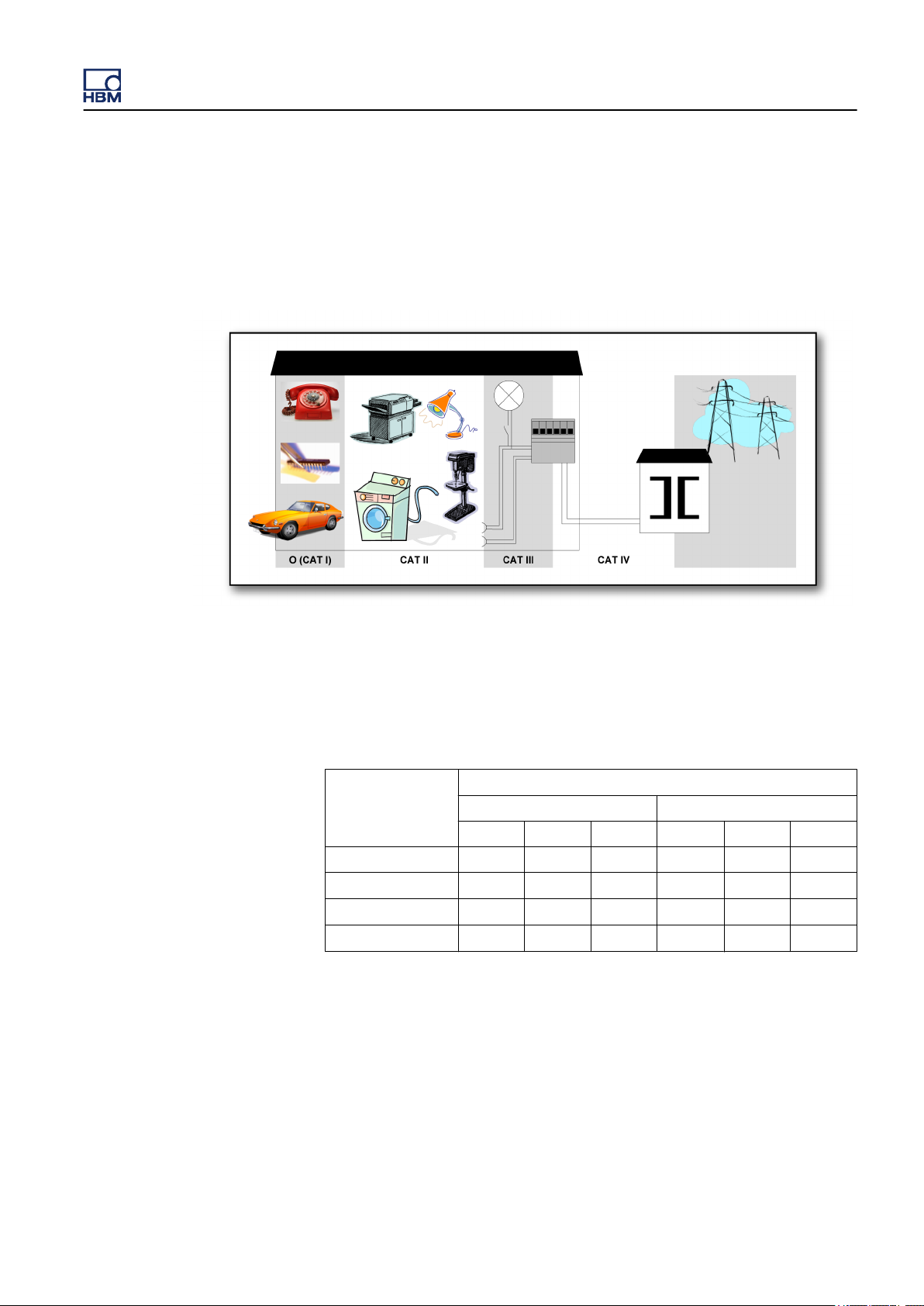
measurement. (See Figure 1.1).
CAT III: This category is for measurements directly connected to the distribution
part of a low-voltage mains installation. Think of measurement of: circuit
breakers, wiring, junction boxes etc. This category is expecting to have a
minimum of two levels of over current protection between the transformer and
connection point of the measurement. (See Figure 1.1).
2 HBM public
Page 3
GN610, GN611 Isolation and type testing
CAT IV:
a low-voltage mains installation. Think of measurement of: over current
protection devices, ripple control units etc. This category is expecting to have
a minimum of one level of over current protection between the transformer and
connection point of the measurement circuit. (See Figure 1.1).
Figure 1.1: Category indication according to IEC 61010-2-030:2010
This category is for measurements directly connected to the source of
Example:
voltage 1000 V DC.
Table 1.1: Insulation test voltages according to IEC 61010
Nominal Voltage
(V RMS or V DC)
≤ 150
> 150 ≤ 300
> 300 ≤ 600
> 600 ≤ 1 000
Using the above table one can deduct that this specification informs the user
the device passed the insulation tests;
4.000 V. The maximum operating input voltage is 1000 V DC. This device is to
be used to measure CAT II circuitry up to 600 V.
A measurement device is specified as 600 V CAT II, maximum input
-2-
030:2010
IEC 61010-2-030:2010
5 sec. AC test (V RMS) Impulse test (V)
CAT II CAT III CAT IV CAT II CAT III CAT IV
840 1.390 2.210 1.550 2.500 4.000
1.390 2.210 3.310 2.500 4.000 6.000
2.210 3.310 4.260 4.000 6.000 8.000
3.310 4.260 6.600 6.000 8.000 12.000
5 sec at 2.210 V RMS and impulse
HBM public 3
Page 4

GN610, GN611 Isolation and type testing
WARNING
Measurement inputs of this instrument should not be used to measure
high-energy signals of measurement categories
CAT IV (IEC 61010-2-30:2010) (e.g. mains measurements) , unless
specifically stated for the specific input.
CAT II, CAT III or
4 HBM public
Page 5
GN610, GN611 Isolation and type testing
1.2 Basic versus reinforced insulation
For reference below one can find the basic insulation and supplementary
insulation as well as the reinforced insulation test values for CATII.
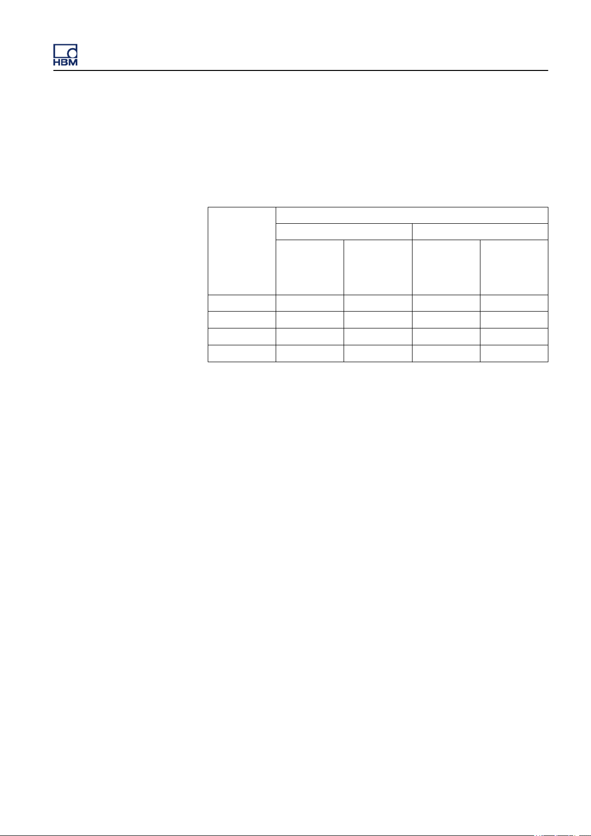
Table 1.2: Test voltages for testing electric strength of solid insulation in
measuring circuits of measurement category II (IEC 61010
-2-
30:2010)
Nominal
voltage line to
neutral a.c
r.m.s. or d.c. of
MAINS being
measured. (V)
≤ 150
> 150 ≤ 300
> 300 ≤ 600
> 600 ≤ 1000
To protect a user from hazardous voltages there are several means of
protection possible. As one can see below basic insulation + supplementary
insulation is a possibility but also reinforced isolation is a means of protection.
The test voltages are different per means as can be found in the above table.
Test voltage
5 s a.c. test V a.c. r.m.s. Impulse test V peak
Basic
insulation and
supplementary
insulation
840 1390 1550 2500
1390 2210 2500 4000
2210 3510 4000 6400
3310 5400 6000 9600
Reinforced
insulation
Basic
insulation and
suplementary
insulation
Reinforced
insulation
HBM public 5
Page 6
GN610, GN611 Isolation and type testing
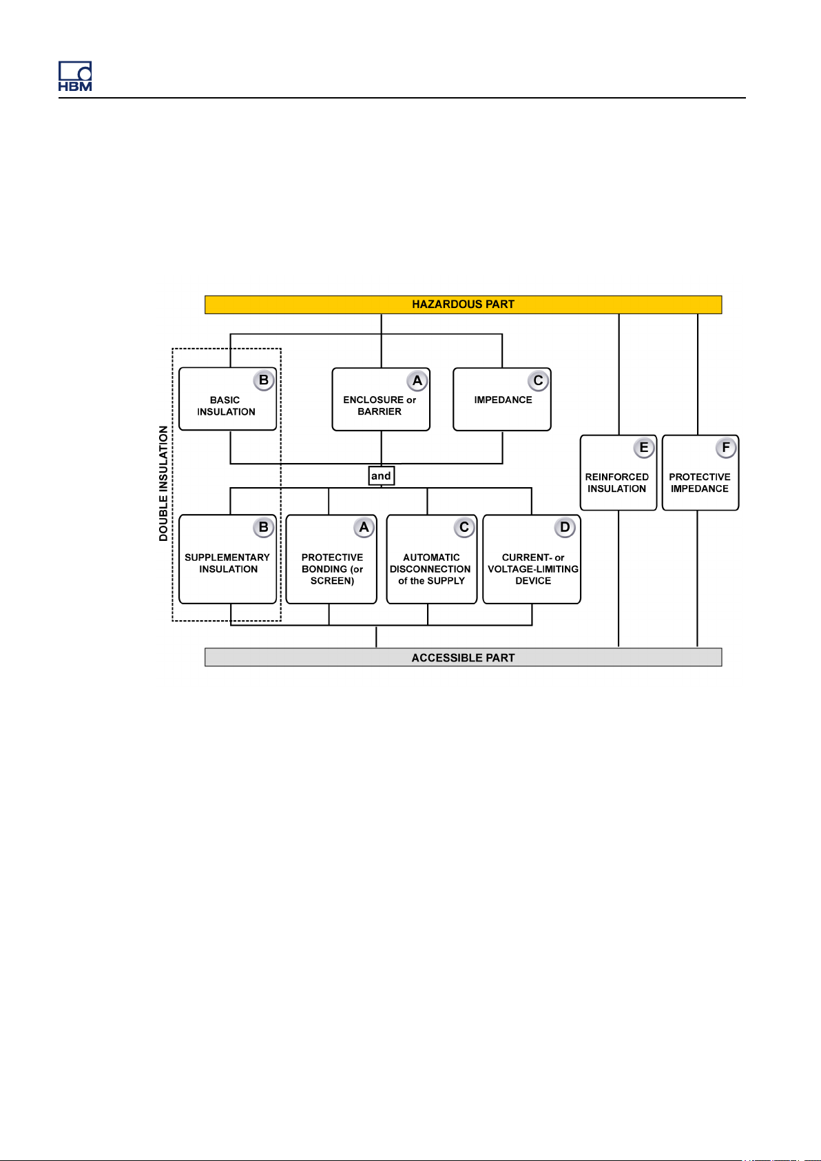
Additional means of protection in case of single fault conditions
Accessible parts shall be prevented from becoming HAZARDOUS LIVE IN
SINGLE FAULT CONDITION. The primary means of protection (see
Figure 1.2) shall be supplemented by one of A, B, C or D. Alternatively one of
the single means of protection E or F shall be used. See Figure 1.2
.
Figure 1.2: Acceptable
Example: A measurement device is specified as 600 V CAT II reinforced
insulation, maximum input voltage 1000 V DC.
Using the above information one can deduct that this specification informs the
user that the measurement device is tested on input to chassis ground 5 s at
3.510 V RMS and impulse 6.400 V. The maximum operating input voltage is
1000 V DC. This device is to be used to measure CAT II circuitry up to 600 V.
6 HBM public
arrangement of protective means against electric shock
Page 7
GN610, GN611 Isolation and type testing
2 GEN series 1 kV input cards GN610, GN611
2.1
Isolation and input of the GN610, GN611
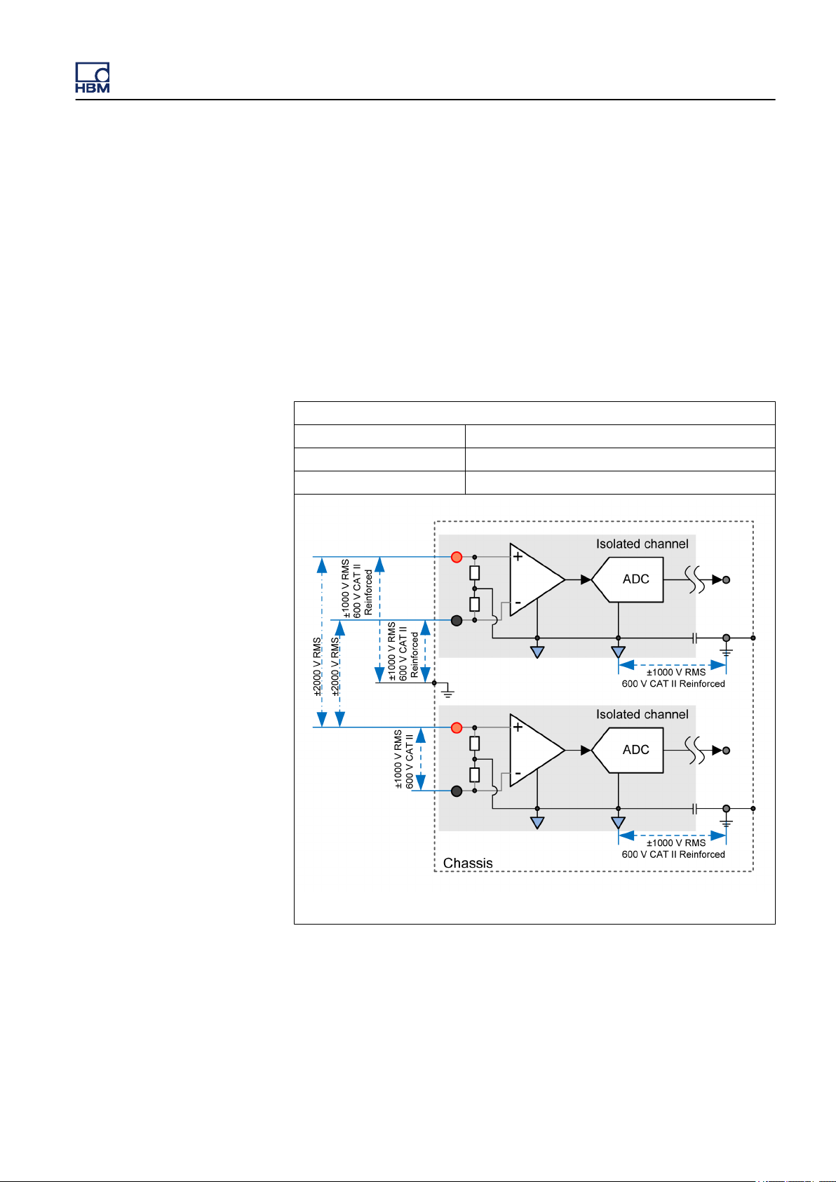
An overview of the GN610, GN611 card isolation and input is given below (see
Figure 2.1). The isolation of the channel to chassis is 1000 V RMS and is also
qualified as 600 V CAT II (or 300 V CAT III). The common mode of the
differential input channel (isolated GND) can be 1000 V RMS with respect to
the chassis. If one channel has common mode at +1000 V and one at
-1000 V (with respect to chassis), the voltage between the two channels is
2000 V. The standards at which the card is certified is IEC61010-1:2010 and
IEC61010-2-30:2010.
Isolation
Input signal to chassis 1000 V RMS, 600 V CAT II (REINFORCED)
Channel to chassis 1000 V RMS, 600 V CAT II (REINFORCED)
Channel to channel 2000 V RMS, (BASIC)
Figure 2.1: Isolation 1kV card overview
l The isolation between channel and chassis is classified as
REINFORCED. This can be seen as double isolation, which is necessary
because the chassis might be accessible (conductive parts can be touched)
to users (personal safety).
HBM public 7
Page 8

GN610, GN611 Isolation and type testing
l Isolation between channels is BASIC, since a channel is not accessible
and there is therefore no direct risk for a user (product safety).
l REINFORCED or DOUBLE isolation has higher test values than BASIC
isolation.
8 HBM public
Page 9

3 Type testing
GN610, GN611 Isolation and type testing
3.1
Channel to chassis isolation test
To qualify the isolation as 1000 V RMS and 600 V CAT II (REINFORCED),
certain tests are performed on some cards during the engineering design
qualification phase. These tests are known as type tests. These tests are
described in the IEC61010-1:2010 and IEC61010-2-30:2010 standards. The
principle of the tests is given below.
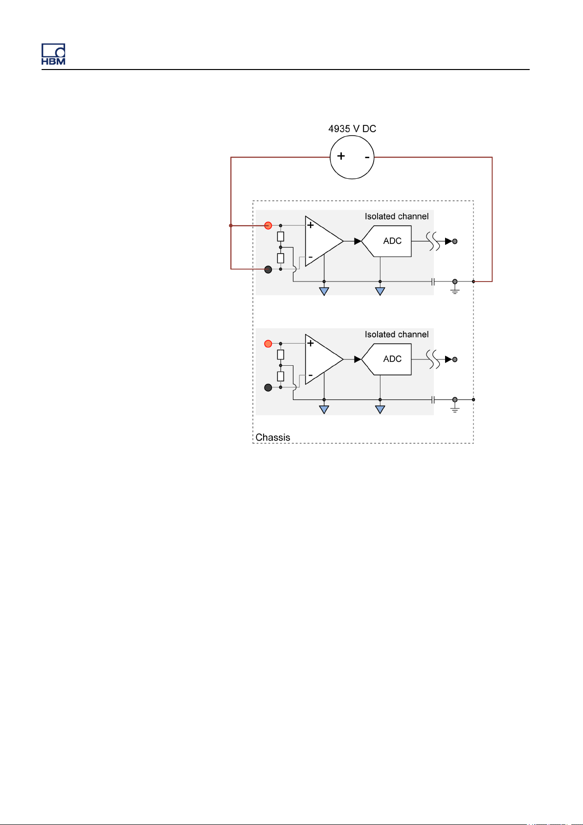
For the isolation barrier test, both the DC and AC tests below (see Figure 3.1
and Figure 3.2) are used with DC voltage √2 higher than the AC voltage. The
test value meets the requirements for 600 V CAT II REINFORCED, the test
value for 1000 V RMS is lower and therefore also covered with this test. Tests
are conducted for one minute, see IEC61010 for details.
Figure 3.1: AC Type test Channel to Chassis
HBM public 9
Page 10
GN610, GN611 Isolation and type testing
Figure 3.2: DC Type test Channel to Chassis
10 HBM public
Page 11

GN610, GN611 Isolation and type testing
3.2 Channel to channel isolation test
For the channel to channel test, both the DC and AC tests below (see
Figure 3.3 and
voltage. The test value meets the requirements for 600 V CAT II REINFORCED,
the value for 2000 V RMS BASIC is lower and therefore also covered with this
test. Tests are conducted for one minute, see IEC61010-1 for details.
Figure 3.4) are used with DC voltage √2 higher than the AC
Figure 3.3: DC Type test Channel to Channel
HBM public 11
Page 12

GN610, GN611 Isolation and type testing
Figure 3.4: AC Type test Channel to Channel
12 HBM public
Page 13

GN610, GN611 Isolation and type testing
4 Production tests
4.1
High potential test
The type tests are performed on a selection of cards to prove the design. Every
produced card will undergo a production test, to verify the correct construction
and safety of the card. The tests called “hipot” (high potential) tests (see
Figure 4.1 and Figure 4.2).
The test are performed in two steps to make sure the channels that are side by
side on the card can with stand the high potential voltages.
1 The inputs of channel 1, 3 and 5 are tested using a 1500 V RMS common
mode signal with ground attached to chassis ground and the inputs of
channel 2, 4 and 6 all connected to chassis ground.
2 The inputs of channel 2, 4 and 6 are tested using a 1500 V RMS common
mode signal with ground attached to chassis ground and the inputs of
channel 1, 3 and 5 all connected to chassis ground.
Figure 4.1: Hipot testing channels 1, 3 and 5
HBM public 13
Page 14

GN610, GN611 Isolation and type testing
Figure 4.2: Hipot testing channels 2, 4 and 6
14 HBM public
Page 15

GN610, GN611 Isolation and type testing
5 Engineering tests
5.1
Overview
Besides the type tests and the production tests, HBM has also performed
several engineering tests to verify the robustness of the design during the
engineering design qualification phase.
Component tests
Every component crossing the isolation barrier is tested and/or examined to
make sure it will pass the type test. The test voltage used is the same high
voltage
up to 6 kV, using a 1.2 μs rise time and an amplitude reduction to 50 % of the
maximum peak voltage in 50 μs after the peak has been reached.
DC as used for the type tests as well as an additional impulse voltage
Figure 5.1: Example of 1.2/50 µs impulse
HBM public 15
Page 16

GN610, GN611 Isolation and type testing
Active input switch test
To guarantee the stability of the channels, the input relays are tested with the
maximum
switched from isolated GND to DC by the input relay, resulting in the 1000 V
being applied to the input as a step pulse.
This test is done with the highest input range (± 1000 V) and also repeated with
the lowest input range (± 20 mV), both with an input voltage of 1000 V and
repeated for over 1000 times. These tests all passed successfully.
input voltage (1000 V) applied. The inputs of the channels have been
Figure 5.2: Engineering test input switching
16 HBM public
Page 17

GN610, GN611 Isolation and type testing
6 GN610, GN611 Protection mechanisms
6.1
Overview
Overvoltage and current protection
All signal inputs are protected against voltage overload. This is specified at
± 1000 V for all ranges except for the ± 1000 V range that is limited to
± 1250 V. Exceeding these limits can damage the input card.
GN610 and GN611 input overload protection
The input section has several methods to protect against voltage overload on
the input.
Every selected input range allows a 200 % overload without any change of input
resistance or auto ranging. This 200 % overrange is designed to allow for
smaller voltage overloads without effecting the measurement. Within this
200 % overload the amplifier is also able to respond with normal rise/fall times
to signal being restored within the standard selected range.
When exceeding the 200 % overload condition, the input impedance might start
to increase. The impedance increase will lower the input current with the
positive effect of lowering the dissipated heat. It is the excessive heat
dissipation that typically damages the input channel.
The first action of the system will be to add an additional current load on the
input signal to create an extra voltage drop on the input series resistance. The
actual additional current depends on several factors and is therefore not
predictable. A negative side effect of this additional current is the extra power
dissipated in the input section which in turn results in additional heat dissipation.
Secondly, within the lower ranges of the amplifier (≤ ± 5 V ranges) the input
section will start switching to disconnect from the input signal to reduce the
power dissipated.
HBM public 17
Page 18

GN610, GN611 Isolation and type testing
Figure 6.1: Input Overload protection - Schematic diagram
Thermal monitor of the input channels
Any overload condition has the same end result: extra heat generated within
the
channel. Not only because of the extra current through the input resistance,
but also because internal amplifier sections will be driving their local output to
maximum levels creating excessive heating within the amplifier.
As a third protective mechanism every input is equipped with a thermal sensor
to monitor the local temperature. When the local temperature reaches
maximum levels the system will automatically start changing the user selected
input range to reduce the dissipated heat. As the heat dissipation will not
immediately start the auto ranging, short overloads will not results in auto
ranging. Longer overload conditions will lead to higher local temperature and
this will start the auto ranging process.
Whenever an overload condition pushes local temperature to above the
maximum level, the input range will be adapted to a factor 10 less sensitive
range. E.g. User selected ± 40 mV range, when required the system will change
the range to ± 400 mV. As this might not be enough due to an even higher
overvoltage, the system keeps on monitoring the local temperature. If the local
temperature doesn’t reduce within the expected response time, the system will
automatically increase the input range with a factor of 10 for a second, third or
how many times required to reach a safe condition not to increase local
temperature anymore.
18 HBM public
Page 19

GN610, GN611 Isolation and type testing
Every one of the automatic range changes will be identified within the
measurement data. Not only will the measured input be scaled correctly with
the adapted input range, but also the exact moment the automatic range
change happens is identified within Perception software.
the highest selectable range is ± 1 kV the ultimate protection for the system
As
will be to disconnect the input from the external signal source. This step will
only be executed if the system is in the ± 1 kV range and local temperature is
still outside maximum operating limits. Disconnecting from the external signal
source is done by grounding the input. When inputs are grounded, the only
connections to the external signal are the input connectors and the input pin of
the ground relay.
Thermal shutdown in critical conditions
This protective scheme allows for any overload condition the input would be
confronted with during normal operation. For any other failure condition that
would result in excessive heat dissipation, the GEN series mainframe has a last
protective stage built in. When local temperatures reach a critical condition the
system will turn-off the mains power automatically to prevent damage to the
system or other systems near the GEN series system. Maximum and critical
temperature conditions are defined as such that it is very unlikely the system
will ever reach this critical condition when operating within its specified
conditions.
HBM public 19
Page 20

GN610, GN611 Isolation and type testing
Figure 6.2: Automatic thermal overload response
Automatic restore of user selected range
As the GEN series system is designed to measure 24 hours per day, 7 days
per week, the automatic ranges switching has the negative side effect of
reduced sensitivity of the amplifier. During the actual overload condition the
channel will not be able to measure the input signal anyhow, so no extra
negative side effects are introduced. If the overload condition disappears and
the system is running unattended, the automatic selected input range will not
be the best measurement range. Therefore the amplifier will remember the
original selected user range and restore this user selection as soon as regular
thermal conditions are restored. Temporary large overload conditions will then
only result in temporary adjusted input sensitivity.
It is expected that the thermal conditions might only be restored because of the
automatic range adaption of the input channel. So the actual overload condition
might not have disappeared yet. If this would be the case, the thermal increase
would re-trigger the automatic range adaption process and the overload is
handled exactly the same way as before.
20 HBM public
Page 21

GN610, GN611 Isolation and type testing
In case the overload condition is permanent, the system keeps on automatic
ranging to reduce the dissipated heat, then restores the user selected range
with the effect of overheating again therefore restarting the automatic ranging
process again. This cycle will repeat forever until the overload condition
disappears.
HBM public 21
Page 22

Index
B
GN610, GN611 Isolation and type testing
Basic versus reinforced insulation
C
Categories according to IEC 61010-2-030:2010 .... 2
Channel to channel isolation test ......................... 11
Channel to chassis isolation test ............................ 9
G
GN610 and GN611 Input Overload protection ..... 17
GN610, GN611 Protection mechanisms
Overvoltage and current protection ................. 17
H
High potential test ................................................. 13
I
Isolation and input of the GN610, GN611 .............. 7
.......................... 5
M
Measurement categories ........................................ 2
22 HBM public
Page 23

Page 24

Head Office
HBM
Im Tiefen See 45
64293 Darmstadt
Germany
Tel: +49 6151 8030
Email: info@hbm.com
France
HBM France SAS
46 rue du Champoreux
BP76
91542 Mennecy Cedex
Tél:+33 (0)1 69 90 63 70
Fax: +33 (0) 1 69 90 63 80
Email: info@fr.hbm.com
UK
HBM United Kingdom
1 Churchill Court, 58 Station Road
North Harrow, Middlesex, HA2 7SA
Tel: +44 (0) 208 515 6100
Email: info@uk.hbm.com
USA
HBM, Inc.
19 Bartlett Street
Marlborough, MA 01752, USA
Tel : +1 (800) 578-4260
Email: info@usa.hbm.com
PR China
HBM Sales Office
Room 2912, Jing Guang Centre
Beijing, China 100020
Tel: +86 10 6597 4006
Email: hbmchina@hbm.com.cn
© Hottinger Baldwin Messtechnik GmbH. All rights reserved.
All details describe our products in general form only.
They are not to be understood as express warranty and do
not constitute any liability whatsoever.
measure and predict with confidence
HBM public
 Loading...