

HBM FS22 SI User Manual
User Manual
English
FS22 SI
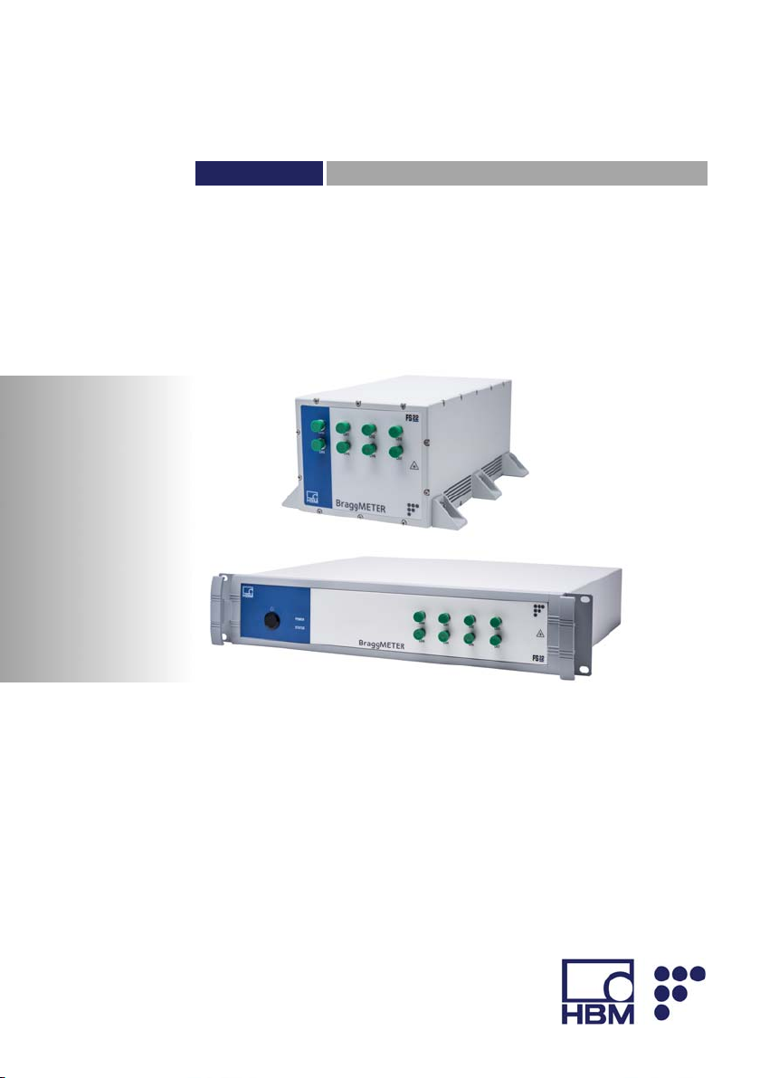
Industrial BraggMETER SI

Hottinger Baldwin Messtechnik GmbH
Im Tiefen See 45
D-64239 Darmstadt
Tel. +49 6151 803-0
Fax +49 6151 803-9100
info@hbm.com
www.hbm.com
HBM FiberSensing, S.A.
Optical Business
Rua Vasconcelos Costa, 277
4470-640 Maia
Portugal
Tel. +351 229 613 010
Fax +351 229 613 020
fibersensing@hbm.com
www.hbm.com/fs
Mat.: 7-2002.4249
DVS: A4249-8.0 HBM: public
10.2017
Interrogator version: v3.0
SW version: v2.4
E Hottinger Baldwin Messtechnik GmbH.
Subject to modifications.
All product descriptions are for general information only.
They are not to be understood as a guarantee of quality or
durability.

English
1 Technical Details 6.........................................
1.1 General Information 6........................................
1.2 System Components 7.......................................
1.3 Technical Data 8............................................
2 Regulatory and Certification Considerations 11................
2.1 Environment Considerations 11.................................
2.1.1 Disposal of your Old Appliance 11...............................
2.2 Laser Safety 12..............................................
2.2.1 Symbols 12..................................................
2.2.2 Class 1 Laser 12..............................................
2.2.3 General Precautions Considerations 13..........................
2.2.4 Certification 14...............................................
3 Operation 15................................................
3.1 Connectors 15................................................
3.1.1 Standard 15..................................................
3.1.2 Rack-Mountable 16...........................................
3.2 Setting Up 17................................................
3.2.1 Power Supply 17.............................................
3.2.2 Optical Connectors 17.........................................
3.2.3 Ethernet Connection 17........................................
3.3 Switching On 18..............................................
3.4 Switching OFF 19.............................................
3.5 Operating the Interrogator 20...................................
3.5.1 Network Properties 20.........................................
3.5.2 Resetting the IP Address of the Interrogator 24...................
3.5.3 Synchronization 25............................................
3.5.4 Operation 28.................................................
4 Measuring 36................................................
4.1 Typical Configuration 36.......................................
FS22 SI A4249-8.0 HBM: public 3

4.1.1 HBM FS Wavelengths 37......................................
4.2 Definitions 38................................................
4.2.1 Wavelength 38...............................................
4.2.2 Power 39....................................................
4.3 Measurement Methods 39.....................................
4.3.1 Conventional 40..............................................
4.3.2 Smart Peak Detection (SPD) 41................................
4.4 Common Measuring Difficulties 43..............................
4.4.1 Dirty Connector 43............................................
4.4.2 Broken Connector 46..........................................
4.4.3 Reflective Fiber Ending 46.....................................
4.4.4 Cut Fiber 47.................................................
4.4.5 Fuse Failure 49...............................................
5 Remote Communications 51..................................
5.1 Communication Protocol Syntax 51.............................
5.1.1 Command Syntax 51..........................................
5.1.2 Common Commands 54.......................................
5.1.3 System Commands 55........................................
5.1.4 Status Commands 57.........................................
5.1.5 Acquisition Commands 57.....................................
5.1.6 Memory Commands 73........................................
6 BraggMONITOR SI Software Details 75........................
6.1 Software Version 75...........................................
6.2 Install and Uninstall Software 76................................
6.2.1 System Requirements 76......................................
6.2.2 Software Installation 77........................................
6.2.3 Software Uninstall 78..........................................
6.3 Running the Software 79.......................................
6.3.1 Network Properties 79.........................................
6.3.2 Regional Settings 79..........................................
4 A4249-8.0 HBM: public FS22 SI

6.3.3 Run as Administrator 80.......................................
7 BraggMONITOR SI User Interface 82..........................
7.1 General Bar 82...............................................
7.1.1 Date and Time 83.............................................
7.1.2 Connecting to the Interrogator 86...............................
7.1.3 Acquisition 88................................................
7.1.4 Software and Interrogator Information 94.........................
7.1.5 Exit Application 94............................................
7.2 Graphical Area 94............................................
7.2.1 Graphical View 95............................................
7.2.2 Numerical View 97............................................
7.2.3 Spectral View 98..............................................
7.2.4 Configuration 107..............................................
7.2.5 SCPI Interface 114.............................................
FS22 SI A4249-8.0 HBM: public 5

Technical Details
1 Technical Details
1.1 General Information
The FS22 - Industrial BraggMETER SI with real time
embedded Smart Peak Detection (SPD) is a continuous
swept laser scanning interrogator specifically designed to
interrogate Fiber Bragg Grating (FBG) based sensors in
industrial environments.
BraggMETER interrogators include a NIST traceable
wavelength reference that provides continuous calibra
tion to ensure system accuracy over long term operation.
The high dynamic range and high output power com
bined with the Smart Peak Detection (SPD) allow high
resolution to be attained even for long fiber leads and
lossy connections.
Multiple sensors can be connected in series in each opti
cal fiber, in combination with one, four or eight optical
channels with parallel acquisition. The FS22 - Industrial
BraggMETER SI is particularly suitable for large scale
sensing networks acquiring a large number of sensors
simultaneously and providing 1 S/s acquisition rates with
sub picometer resolution.
The BraggMETER is available either in Standard and
Rack-mountable formats. This Manual applies to the fol
lowing equipment:
Standard
K-FS22-01-010-120 FS22 – Industrial BraggMETER SI Single channel
K-FS22-03-010-120 FS22 – Industrial BraggMETER SI Single channel
K-FS22-01-010-420 FS22 – Industrial BraggMETER SI Quad channel
K-FS22-03-010-420 FS22 – Industrial BraggMETER SI Quad channel
6 A4249-8.0 HBM: public FS22 SI

Technical Details
K-FS22-01-010-820 FS22 – Industrial BraggMETER SI Octo channel
K-FS22-03-010-820 FS22 – Industrial BraggMETER SI Octo channel
Rack-Mountable
K-FS22-11-010-120 FS22 – Industrial BraggMETER SI Single channel
K-FS22-13-010-120 FS22 – Industrial BraggMETER SI Single channel
K-FS22-11-010-420 FS22 – Industrial BraggMETER SI Quad channel
K-FS22-13-010-420 FS22 – Industrial BraggMETER SI Quad channel
K-FS22-11-010-820 FS22 – Industrial BraggMETER SI Octo channel
K-FS22-13-010-820 FS22 – Industrial BraggMETER SI Octo channel
HBM FiberSensing interrogators are compatible with
catman software, a powerful tool for data acquisition and
processing.
1.2 System Components
The FS22 - Industrial BraggMETER SI set includes:
Standard format Rack-mountable format
- Interrogator
- Power cord
- Power adapter
- Ethernet cable (L ~2 m)
- Mounting blocks with M6
screws
- Connector protection caps
- Quick guide
- Digital support material
- Calibration certificate
- Interrogator
- Power cord
- Ethernet cable (L ~2 m)
- Connector protection caps
- Quick guide
- Digital support material
- Calibration certificate
FS22 SI A4249-8.0 HBM: public 7

Technical Details
1.3 Technical Data
Wavelength Measurement
Range 100 nm (1500 to 1600 nm)
Resolution/Repeatability
Stability/Reproducibility
Optical channels
2)
Maximum sensors Operation mode Conventional With SPD
Sample rate 1 S/s
Optical detection Logarithmic
Dynamic range
3)
Laser Source
Optical output power
Single 0 dBm
Quad -3 dBm
Octo -6 dBm
Linewidth < 500 MHz
Connectors
Optical FC/APC and SC/APC
Electrical Standard: Weidmüller Terminal Block
Communication RJ45 Ethernet
Control
Interface Ethernet (TCP/IP)
Commands SCPI (ASCII textual strings)
Synchronization NTP
1)
1)
<0.5 pm
1 pm
1, 4 or 8
Per OC 125 125
Total 500 1000
> 50 dB
4)
SLDF 5.08 2-way supplied with 100-230 V power
adapter and Type F plug cable
5)
Rack-Mountable: C14 (IEC/EN 60320-1) supplied
with Type F plug cable
5)
6)
8 A4249-8.0 HBM: public FS22 SI

Technical Details
Features
OSA trace Continuous (wavelength, absolute power)
Sleep mode Yes
Local data logging Yes
Storage capacity
8)
2 GB
Environmental
Operation temperature 10 to 40 ºC
Operation humidity < 90% at 40 ºC
Storage temperature -20 to 70 ºC
Storage humidity <95% (non-condensing)
Shock Resistance 20 g; 11 ms (EN60068-2-27)
Vibration Resistance
9)
2.5 g (EN60068-2-6)
Mechanical
Dimensions (w x h x d) Standard: 155 x 125 x 275 mm
Rack-Mountable: 483 x 88 x 400 mm
Mounting Standard: 6 screws M6
Rack-Mountable: 19" rack mountable (2U)
Enclosure Aluminum
Weight Standard: 4.5 kg (without mounting brackets)
Rack-Mountable: 7 kg
Power
Voltage Standard: 11-36 VDC
Rack-Mountable: 100-240 VAC 50-60 Hz
10)
4)
17.5 W
Consumption
Nominal
7)
FS22 SI A4249-8.0 HBM: public 9

Technical Details
Stand by 0.4 W
Sleep mode 0.4 W
1)
As per NIST Technical Note 1297: Repeatability [§D.1.1.2], σ of measurements carried out under
the same conditions; Reproducibility [§D.1.1.3], σ of measurements carried out under the full
operation conditions (temperature and power cycles). Above mentioned measurements accuracy
[§D.1.1.1] carried out using calibrated instrument against a NIST traceable gas cell. Further details
on HBM FiberSensing technical notes
2)
With simultaneous acquisition
3)
Considered as the ratio between the optical power emitted at an optical channel and the minimum
detectable optical power reflected by a fiber Bragg grating
4)
Typical values
5)
Different plug formats can be added upon request
6)
Standard Commands for Programmable Instruments
7)
Full spectrum trace with 20001 points acquired over the 100 nm range (sampled every 5 pm)
8)
Up to 6000 hours of data storage, considering 100 sensors
9)
Sinusoidal vibration
10)
Peak consumption may reach 38 W (during startup)
10 A4249-8.0 HBM: public FS22 SI
Regulatory and Certification Considerations
2 Regulatory and Certification Considerations
2.1 Environment Considerations
2.1.1 Disposal of your Old Appliance
When the attached symbol combination - crossed-out
wheeled bin and solid bar symbol is attached to a product
it means the product is covered by the European Direc
tive 2002/96/EC and is applicable in the European Union
and other countries with separate collection systems.
All electrical and electronic products should be disposed
of separately from the municipal waste stream or house
hold via designated collection facilities appointed by the
government or the local authorities. The correct disposal
of your old appliance will help prevent potential negative
consequences for the environment and human health.
For more detailed information about disposal of your old
appliance, please contact your city office, waste disposal
service or distributor that purchased the product.
HBM FiberSensing is a manufacturer registered in the
ANREEE - "Associação Nacional para o Registo de
Equipamentos Eléctricos e Electrónicos" under number
PT001434. HBM FiberSensing celebrated a "Utente"
type contract with Amb3E - "Associação Portuguesa de
Gestão de Resíduos de Equipamentos Eléctricos e Elec
trónicos", which ensures the transfer of Electrical and
Electronic appliance waste management, i.e. placing
Electronic and Electrical appliances in the Portuguese
market, from the manufacturer HBM FiberSensing to
Amb3E.
FS22 SI A4249-8.0 HBM: public 11
Regulatory and Certification Considerations
2.2 Laser Safety
The FS22 - Industrial BraggMETER SI contains a laser in
its core. A laser is a light source that can be dangerous
to people exposed to it. Even low power lasers can be
hazardous to a person's eyesight. The coherence and
low divergence of laser light means that it can be focused
by the eye into an extremely small spot on the retina,
resulting in localized burning and permanent damage.
The lasers are classified by wavelength and maximum
output power into the several safety classes: Class 1,
Class 1 M, Class 2, Class 2 M, Class 3R and Class 4.
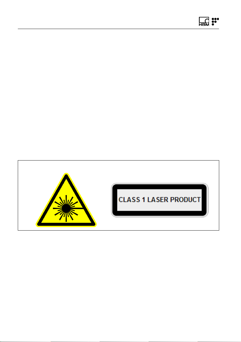
2.2.1 Symbols
Warning symbol Class 1 Laser symbol
2.2.2 Class 1 Laser
The FS22 - Industrial BraggMETER SI is a class 1 laser
product:
«Any laser or laser system containing a laser that cannot
emit laser radiation at levels that are known to cause eye
or skin injury during normal operation. »
12 A4249-8.0 HBM: public FS22 SI

Regulatory and Certification Considerations
It is safe under all conditions of normal use. No safety
requirements are needed to use Class 1 laser devices.
This product contains a laser within an enclosure that
prevents exposure to the radiation and that cannot be
opened without shutting down the laser.
2.2.3 General Precautions Considerations
Everyone who uses a laser equipment should be aware
of the risks.
The laser radiation is not visible to the human eye but it
can seriously damage user's eyesight.
The laser is enabled when the interrogator is turned on.
Users should never put their eyes at the level of the hori
zontal plane of the optical adapters of the interrogator or
uncovered optical connectors.
Adequate eye protection should always be required if
there is a significant risk for eye injury.
When an optical channel is not in use (no optical connec
tor plugged to the interrogator), a proper connector cap
must be used. The optical connectors are subjected to
maintenance and/or inspection. Please refer to
section 4.4.1 “Dirty Connector“ for maintenance
procedure.
Do not attempt to open or repair a malfunctioning inter
rogator. It must be returned to HBM FiberSensing for
repair and calibration.
FS22 SI A4249-8.0 HBM: public 13

Regulatory and Certification Considerations
2.2.4 Certification
This product carries the CE marking and complies with
the applicable international requirements for product
safety and electromagnetic compatibility, according to the
following Directives:
S Low Voltage Directive (LVD) 2014/35/EU - Electrical
Safety
S Electromagnetic Compatibility (EMC) Directive
2014/30/EU
It is in compliance with the EN61326/EN55011 Emission
Radiated Test Class A, under the Electromagnetic Com
patibility Standard.
The corresponding Declaration of Conformity is available
upon request.
14 A4249-8.0 HBM: public FS22 SI
3 Operation
Front view Back view
Operation
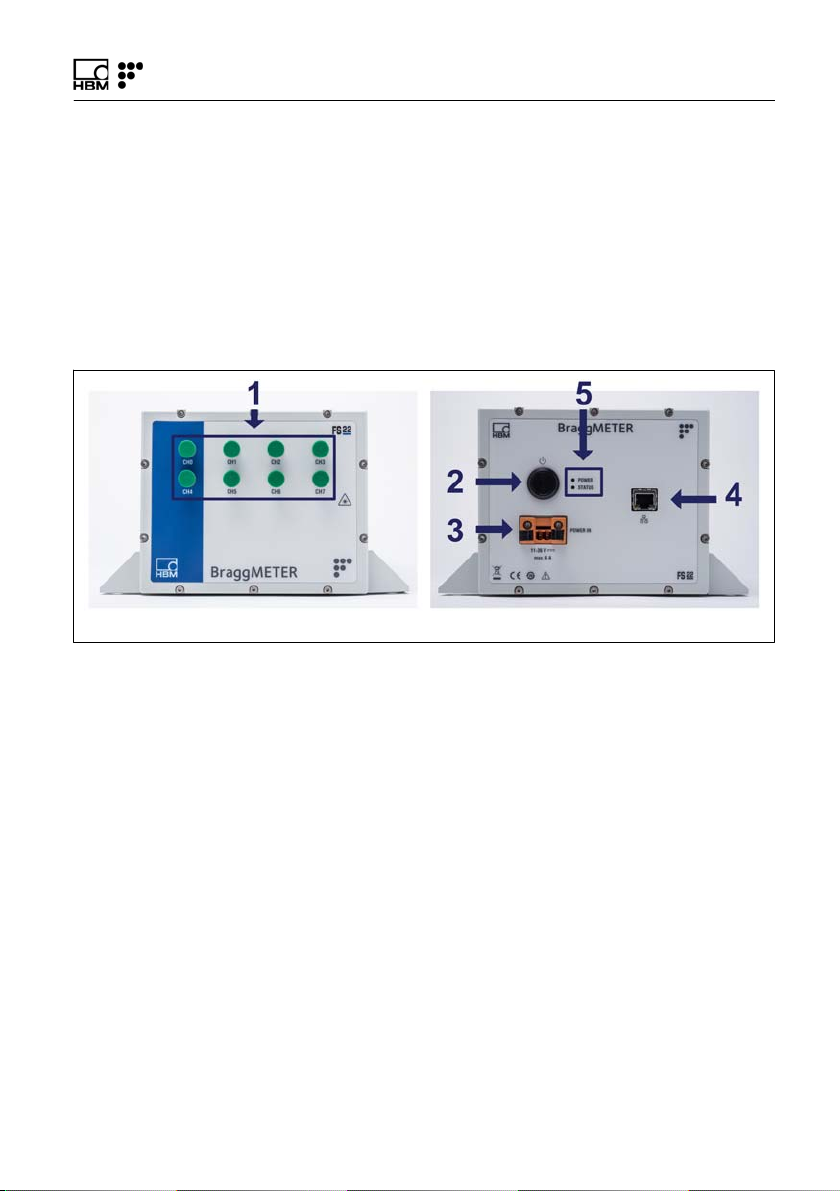
3.1 Connectors
3.1.1 Standard
Fig. 3.1
The connectors and buttons on Fig. 3.1 are:
1 Optical Output Connectors
2 ON/OFF Button
3 Power Connector
4 Ethernet Connector
5 POWER and STATUS LEDs
FS22 SI A4249-8.0 HBM: public 15
Operation
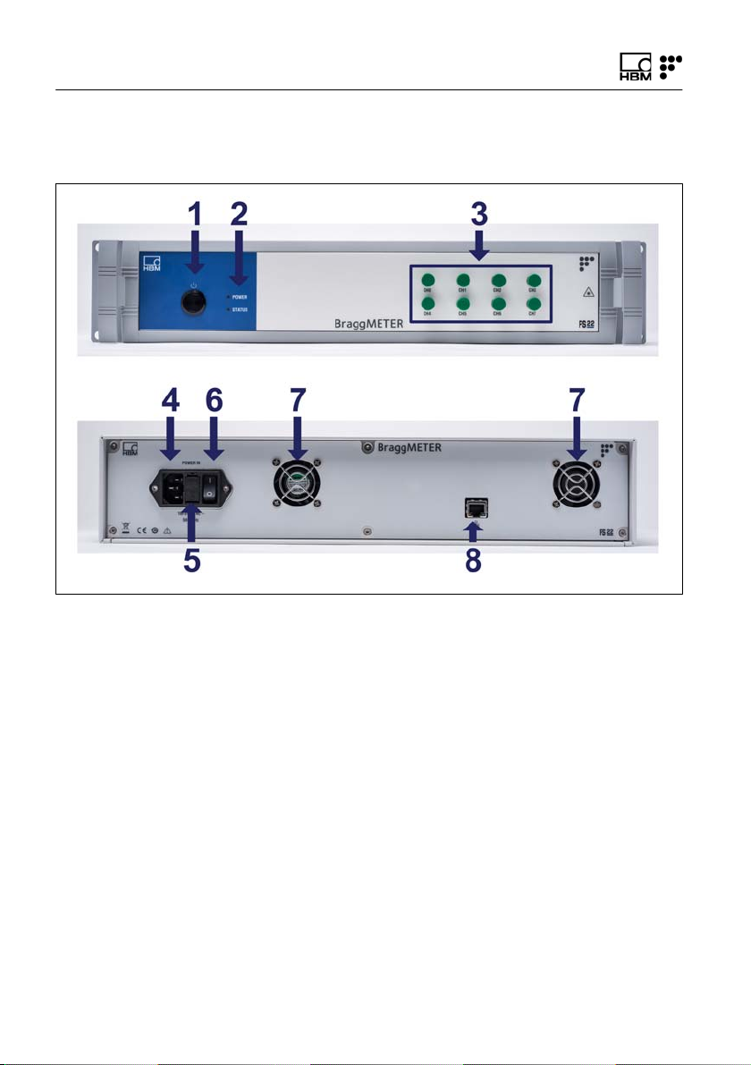
3.1.2 Rack-Mountable
Front view
Back view
Fig. 3.2
The connectors and buttons on Fig. 3.2 are:
1 ON/OFF Button
2 POWER and STATUS LEDs
3 Optical Output Connectors
4 Power Connector
5 Electric fuse
6 Safety Power Button
7 Fans
8 Ethernet Connector
16 A4249-8.0 HBM: public FS22 SI

Operation
3.2 Setting Up
3.2.1 Power Supply
To start the FS22 - Industrial BraggMETER SI interroga
tor connect the power cable to the interrogator Power
Connector (number 3 on Fig. 3.1 or number 4 on
Fig. 3.2). To acknowledge proper power supply, the
POWER LED will turn green during 2 seconds after con
necting the power supply.
3.2.2 Optical Connectors
The FS22 - Industrial BraggMETER SI can be purchased
either with FC/APC, or SC/APC optical connectors. num
ber 1 on Fig. 3.1 exemplifies FC/APC connectors.
Attention should be paid to the cleaning of the optical
connectors. A dirty connector can compromise the mea
surement and will degrade the interrogator performance.
It is advisable to frequently clean the connectors using
appropriate tools.
FS22 - Industrial BraggMETER SI can have one, four or
eight optical channels in parallel.
3.2.3 Ethernet Connection
Connect the Ethernet RJ45 connector directly to a PC
using a Ethernet cross-over cable, or to a network con
nector using a direct Ethernet cable (in this case, the
FS22 - Industrial BraggMETER SI must be in the same
subnet as your Local Network).
FS22 SI A4249-8.0 HBM: public 17
Operation
Important
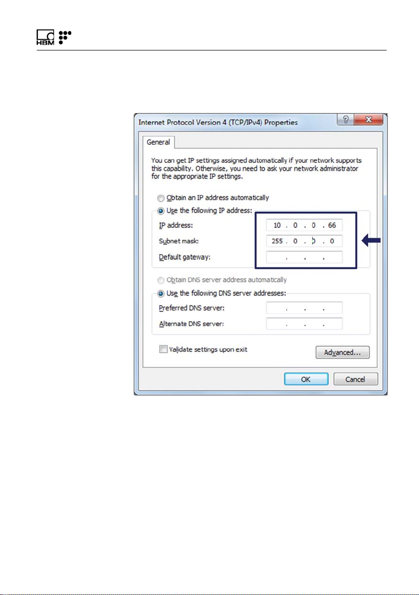
The interrogator default network configuration is
“10.0.0.10:255.0.0.0:0.0.0.0".
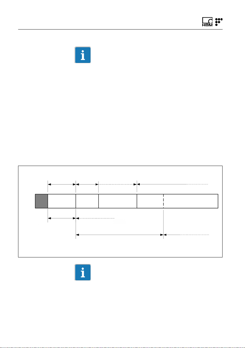
3.3 Switching On
Pressing the ON/OFF button will start the interrogator.
The STATUS LED will start blinking at 2 Hz. After
approximately 30 seconds it will start blinking at 1 Hz.
This means that the interrogator is already on and
responsive, but the optoelectronic module is still warming
up. After approximately 90 seconds it should stay on per
manently. This means that the interrogator is able to
measure.
Status LED
Blinking 2 Hz
CorrectWrong
ON(0s) ~10s >30s <90s ?s
Status LED
Blinking 2 Hz
Status LED
Blinking 1 Hz
(initialization issues)
Status LED
Blinking 1 Hz
Status LED
On
Status LED
Blinking 5 Hz
Status LED
Blinking 5 Hz
(measurement issues)
Information
If the interrogator does not start correctly, the STATUS
LED will blink faster. If this happens please contact HBM
FiberSensing technical support.
18 A4249-8.0 HBM: public FS22 SI
Operation
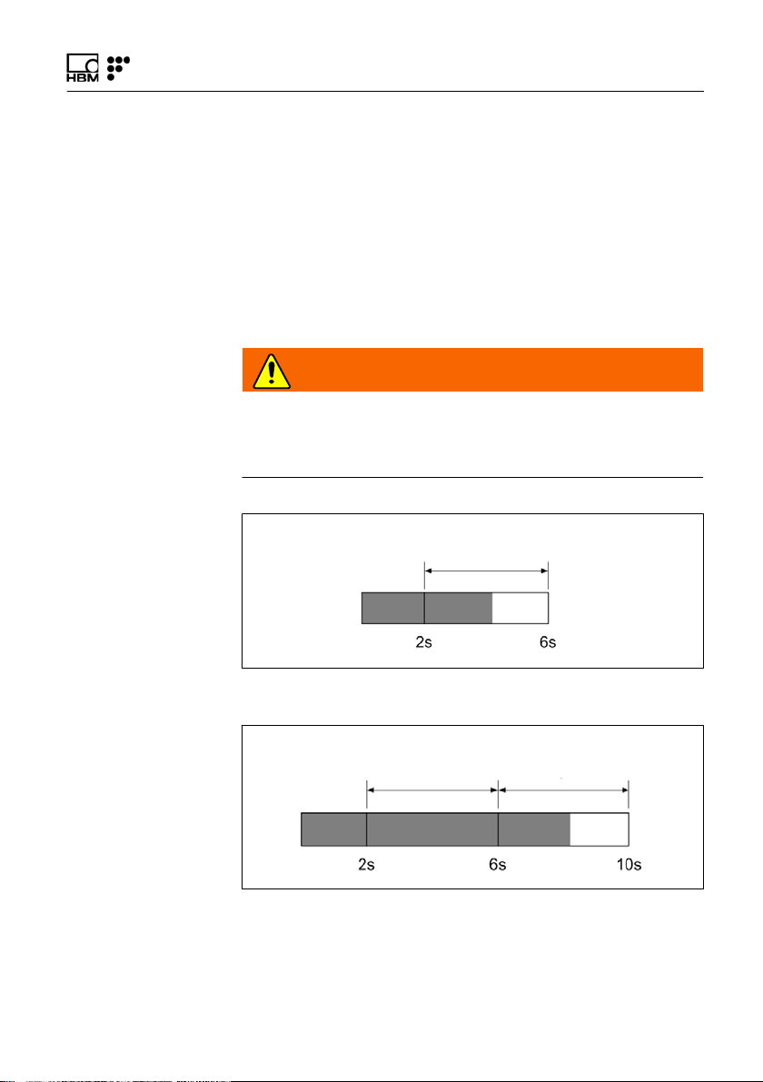
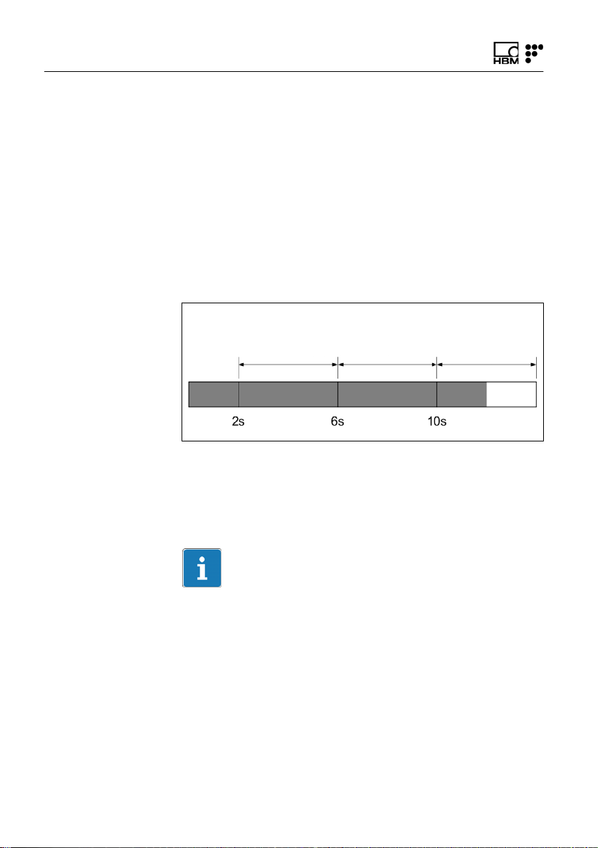
3.4 Switching OFF
To avoid accidental shut-down of the interrogator, it is
necessary to press the “ON/OFF" button between 2 and
6 seconds (Fig. 3.3).
If for some reason the 6 seconds are exceeded the user
can release the button before 10 seconds are reached
and the interrogator will remain ON (Fig. 3.4).
WARNING
If the ON/OFF button is pressed more than 10 seconds
irreversible changes on the interrogator configuration are
performed.
POWER LED
blinking at 1 Hz
Fig. 3.3
POWER LED
blinking at 1 Hz
Fig. 3.4
POWER LED
ON
FS22 SI A4249-8.0 HBM: public 19

Operation
3.5 Operating the Interrogator
3.5.1 Network Properties
To operate the FS22 - Industrial BraggMETER SI from a
personal computer, the PC network properties should be
set so that both elements are configured in the same
subnet.
To configure your personal computer so that it is on the
same subnet as the default for the interrogator, proceed
as follows:
► On the control panel choose Network Connections.
► Select the LAN connection. The window displayed in
Fig. 3.5 will appear. Click on Properties.
20 A4249-8.0 HBM: public FS22 SI

Operation
Fig. 3.5
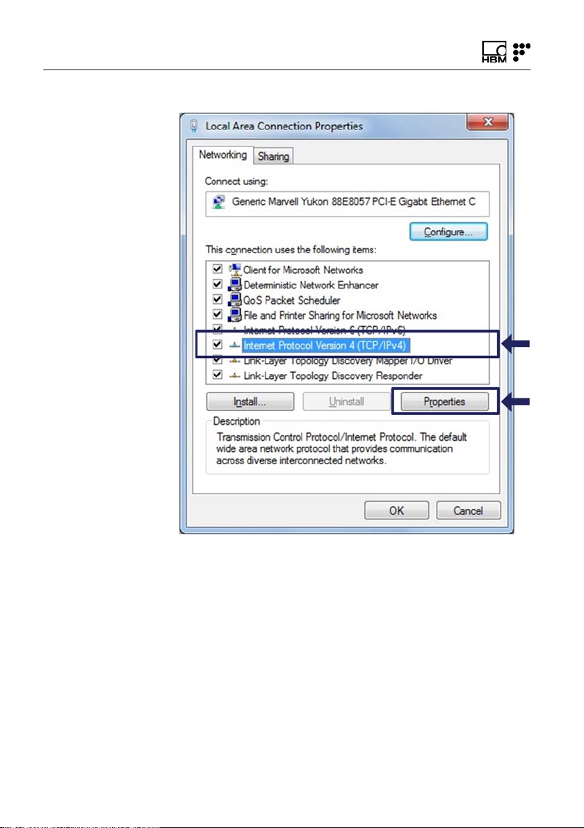
► Select the Internet Protocol (TCP/IP) and click on the
button Properties (Fig. 3.6).
FS22 SI A4249-8.0 HBM: public 21
Operation
Fig. 3.6
22 A4249-8.0 HBM: public FS22 SI
Operation
► Set the IP address and the subnet mask as in
Fig. 3.7.
Fig. 3.7
► Press OK.
FS22 SI A4249-8.0 HBM: public 23
Operation
3.5.2 Resetting the IP Address of the Interrogator
If for any chance there is the need to physically change
the IP address of the interrogator, there is a reset proce
dure that consists on pressing the ON/OFF button for
more than 10 seconds.
When the button is being pressed for 10 seconds the
POWER LED blinks 3 times and goes OFF. At this
moment the ON/OFF button can be released and the
reset of IP address will happen.
POWER LED
blinking at 1 Hz
Fig. 3.8
POWER LEDONPOWER LED
blinks 3 times
and goes OFF
This procedure resets the interrogator changing its IP
address to the default and its measuring settings to the
last stored.
Information
The interrogator default network properties are
“10.0.0.10:255.0.0.0:0.0.0.0".
24 A4249-8.0 HBM: public FS22 SI

Single interrogator
Operation
3.5.3 Synchronization
In order to achieve synchronous measurements between
different devices the NTP (Network Time Protocol) syn
chronization via Ethernet must be used.
Each optical Interrogator can synchronize its internal
clock with an NTP server. It is possible to achieve accu
racies of 1ms or higher, depending on whether or not a
dedicated NTP server is being used.
Further information about NTP can be found at
http://www.ntp.org
.
Measuring Systems Typology
A measurement system can be as simple as a single
interrogator or a bit more complex with combined inter
rogators with the same or different sampling rates, and
interrogators combined with other equipment.
For the usage of a single interrogator no special synchro
nization is needed.
BraggMONITOR SI software can only operate one inter
rogator at a time. If an NTP server is running on the
same PC as the BraggMONITOR SI, the interrogator
internal clock – hence BraggMONITOR SI – will sync.
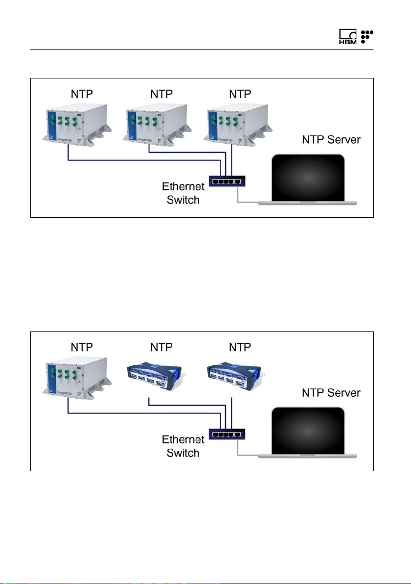
Multiple
interrogators
If more than one interrogator is used, synchronization
becomes important and if an NTP server is running the
equipment will start synching as soon as a first communi
cation from the server is received.
FS22 SI A4249-8.0 HBM: public 25
Operation
Fig. 3.9
Hybrid
A hybrid measurement system is a system composed by
different equipment types and technologies that can be
operated with different sampling rates. Taking the exam
ple of HBM families a hybrid system could be a combina
tion of Interrogators with QuantumX.
Fig. 3.10
26 A4249-8.0 HBM: public FS22 SI

Operation
Synchronization is again of extreme importance in such
systems. When an NTP server is running the Interrogator
will start synching as soon as a first communication from
the server is received.
For details on the other equipment please refer to their
respective user manuals.
Synchronization process
Each interrogator synchronizes its internal clock with the
NTP server. Upon starting, all devices and the NTP
server need some settling time to achieve the best syn
chronism possible.
The following features for NTP synchronization are avail
able:
Number of devices
to be synchronized
Synchronization
accuracy
Synchronization
settling time
Synchronization
master
Unlimited
10 μs to 10 ms
Up to 30 min during first start, up to 2 min during restart
External SyncMaster, e.g. PC
For a good synchronization, the dedicated NTP server
should run continuously. The accuracy is described by
the two values:
S Offset: average deviation from time server
S Jitter: typical variation range of the offset value
The clock synchronization is classified using the following
offset intervals:
S <500 μs: excellent
S <1 ms: very good
FS22 SI A4249-8.0 HBM: public 27

Operation
S <2 ms: good
S <5 ms: acceptable
S <10ms: poor
S >10ms: not acceptable
A successful NTP Sync is achieved if the offset between
the internal clock of the device and the NTP server is
below 5ms.
The quality of the NTP synchronization can be queried
using the SCPI commands (please refer to section “Syn
chronization” on page 53 for further details).
3.5.4 Operation
The FS22 - Industrial BraggMETER SI interrogator can
be fully controlled using standard SCPI syntax com
mands (for a complete command list, please refer to sec
tion 5.1 “Communication Protocol Syntax” on page 51).
Using the Provided Drivers
These drivers can be used within the LabVIEWTM envi
ronment. To develop custom applications using this
language, copy the drivers' library supplied on the CD.
A set of ready to use examples to run on LabVIEWTM is
also provided.
Important
Before using the provided LabVIEWTM examples on a
PC, make sure the Regional and Language options (in
standards and formats) are defined as dot for decimal
symbol, comma for digit grouping symbol and dash for
date separation.
28 A4249-8.0 HBM: public FS22 SI

0 Error
1 Ready
2 Free acquisition
3 Continuous
acquisition
4 Scheduled
acquisition
5 Warming-up
Operation
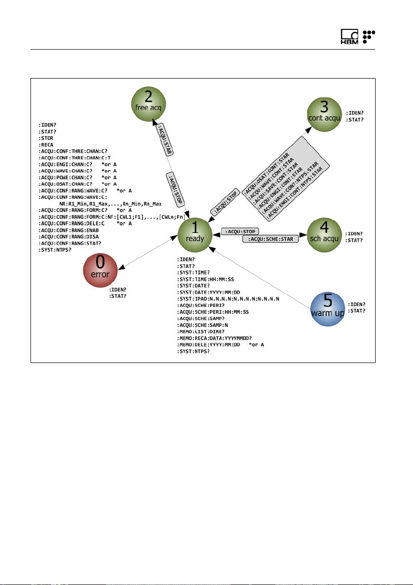
Operational States
The FS22 - Industrial BraggMETER SI interrogator has
six operational states:
The error state corresponds to a malfunction of the opto
electronic module of the interrogator. The system can
only recover from this state by resetting.
In the ready state, the FS22 - Industrial BraggMETER SI
is ready to start acquisition.
The free acquisition state enables the FS22 - Industrial
BraggMETER SI interrogator to perform single measure
ments on a specified optical channel. The interrogator
can be configured in terms of threshold and the corre
sponding configuration can be stored for further mea
surements.
The continuous acquisition state allows continuous wave
length acquisition over all optical channels and also per
forms continuous OSA trace acquisition at 1 S/s.
The scheduled acquisition state allows periodic data
acquisition with a pre-defined period and number of sam
ples while saving data to the internal interrogator mem
ory. Whenever the acquisition period minus the number
of samples (at 1 S/s rate) is higher than 10 minutes, the
interrogator will enter into sleep mode during inactive
time intervals, to reduce power consumption. The mini
mum period is 5 s and the number of samples (at 1 S/s)
cannot overcome the defined period.
The FS22 - Industrial BraggMETER SI interrogator starts
on the warming-up state that enables the settling of the
operation parameters and recall of the acquisition con
figuration.
FS22 SI A4249-8.0 HBM: public 29
Operation
Fig. 3.11
Commands for different Operational States
0 Error
In the error state, the FS22 - Industrial BraggMETER SI
only replies to the commands:
:IDENtification?
:STATus?
1 Ready
In the ready state, the FS22 - Industrial BraggMETER SI
replies to common commands:
:IDENtification?
30 A4249-8.0 HBM: public FS22 SI
 Loading...