

Page 1
User Manual
English
FS22 DI
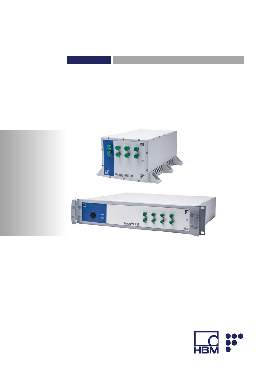
Industrial BraggMETER DI
Page 2

Hottinger Baldwin Messtechnik GmbH
Im Tiefen See 45
D-64239 Darmstadt
Tel. +49 6151 803-0
Fax +49 6151 803-9100
info@hbm.com
www.hbm.com
HBM FiberSensing, S.A.
Optical Business
Rua Vasconcelos Costa, 277
4470-640 Maia
Portugal
Tel. +351 229 613 010
Fax +351 229 613 020
fibersensing@hbm.com
www.hbm.com/fs
Mat.: 7-2002.4248
DVS: A4248-6.0 HBM: public
10.2017
Interrogator version: v2.0
SW version: v1.7
E Hottinger Baldwin Messtechnik GmbH.
Subject to modifications.
All product descriptions are for general information only.
They are not to be understood as a guarantee of quality or
durability.
Page 3

English
1 Technical Details 6.........................................
1.1 General Information 6........................................
1.2 System Components 7.......................................
1.3 Technical Data 8............................................
2 Regulatory and Certification Considerations 10................
2.1 Environment Considerations 10.................................
2.1.1 Disposal of your Old Appliance 10...............................
2.2 Laser Safety 11..............................................
2.2.1 Symbols 11..................................................
2.2.2 Class 1 Laser 11..............................................
2.2.3 General Precautions Considerations 12..........................
2.2.4 Certification 13...............................................
3 Operation 14................................................
3.1 Connectors 14................................................
3.1.1 Standard 14..................................................
3.1.2 Rack-Mountable 15...........................................
3.2 Setting Up 16................................................
3.2.1 Power Supply 16.............................................
3.2.2 Optical Connectors 16.........................................
3.2.3 Ethernet Connection 17........................................
3.3 Switching On 17..............................................
3.4 Switching Off 18..............................................
3.5 Operating the Interrogator 19...................................
3.5.1 Network Properties 19.........................................
3.5.2 Interrogator IP Address 23.....................................
3.5.3 Synchronization 24............................................
3.5.4 Operation 27.................................................
4 Measuring Examples 34......................................
4.1 Typical Configuration 34.......................................
FS22 DI A4248-6.0 HBM: public 3
Page 4

4.1.1 HBM FS Wavelengths 36......................................
4.2 Definitions and Operation Methods 37...........................
4.2.1 Wavelength 37...............................................
4.2.2 Power 38....................................................
4.2.3 Gain 39.....................................................
4.2.4 Threshold 40.................................................
4.3 Common Measuring Difficulties 41..............................
4.3.1 Dirty Connector 41............................................
4.3.2 Broken Connector 43..........................................
4.3.3 Reflective Fiber Ending 43.....................................
4.3.4 Cut Fiber 44.................................................
4.3.5 Fuse Failure 46...............................................
5 Remote Communications 48..................................
5.1 Communication Protocol Syntax 48.............................
5.1.1 Command Syntax 48..........................................
5.1.2 Common Commands 50.......................................
5.1.3 System Commands 51........................................
5.1.4 Acquisition Commands 54.....................................
6 BraggMONITOR DI Software Details 63........................
6.1 Software Version 63...........................................
6.2 Install and Uninstall Software 63................................
6.2.1 System Requirements 63......................................
6.2.2 Software Installation 64........................................
6.2.3 Software Uninstall 65..........................................
6.3 Running the Software 65.......................................
6.3.1 Network Properties 65.........................................
6.3.2 Run as Administrator 66.......................................
7 BraggMONITOR DI User Interface 68..........................
7.1 General Bar 69...............................................
7.1.1 Acquisition 70................................................
4 A4248-6.0 HBM: public FS22 DI
Page 5

7.1.2 Software and Interrogator Information 75.........................
7.1.3 Exit Application 75............................................
7.2 Graphical Area 75............................................
7.2.1 Graphical View 76............................................
7.2.2 Numerical View 77............................................
7.2.3 Spectral View 78..............................................
7.2.4 FFT View 80.................................................
7.2.5 Configuration 81..............................................
7.2.6 SCPI Interface 89.............................................
FS22 DI A4248-6.0 HBM: public 5
Page 6

Technical Details
1 Technical Details
1.1 General Information
The Industrial BraggMETER DI is a continuous swept
laser scanning interrogator for fiber Bragg grating (FBG)
sensors. It includes a traceable wavelength reference
that provides continuous calibration to ensure system
accuracy over long term operation. The high dynamic
range and high output power allow high resolution to be
attained even for long fiber leads and lossy connections.
Multiple sensors can be connected in series in each opti
cal fiber, which in combination with the eight optical chan
nels with parallel acquisition for the FS22 - Industrial
BraggMETER DI, makes it particularly suitable for large
scale sensing networks, acquiring a large number of sen
sors simultaneously, providing 1000 S/s acquisition rates
with sub picometer resolution.
The BraggMETER is available in Standard and Rackmountable format. This Manual applies to the following
equipment:
Standard
K-FS22-01-500-120 FS22 – Industrial BraggMETER DI Single channel
K-FS22-03-500-120 FS22 – Industrial BraggMETER DI Single channel
K-FS22-01-500-420 FS22 – Industrial BraggMETER DI Quad channel
K-FS22-03-500-420 FS22 – Industrial BraggMETER DI Quad channel
K-FS22-01-500-820 FS22 – Industrial BraggMETER DI Octo channel
K-FS22-03-500-820 FS22 – Industrial BraggMETER DI Octo channel
6 A4248-6.0 HBM: public FS22 DI
Page 7
Technical Details
Rack-Mountable
K-FS22-11-500-120 FS22 – Industrial BraggMETER DI Single channel
K-FS22-13-500-120 FS22 – Industrial BraggMETER DI Single channel
K-FS22-11-500-420 FS22 – Industrial BraggMETER DI Quad channel
K-FS22-13-500-420 FS22 – Industrial BraggMETER DI Quad channel
K-FS22-11-500-820 FS22 – Industrial BraggMETER DI Octo channel
K-FS22-13-500-820 FS22 – Industrial BraggMETER DI Octo channel
HBM FiberSensing interrogators are compatible with
catman® software, a powerful tool for data acquisition
and processing.
1.2 System Components
The Industrial BraggMETER DI set includes:
Standard format Rack-mountable format
- Interrogator
- Power cord
- Power adapter
- Ethernet cable (L ~2 m)
- Mounting blocks with M6 screws
- Connector protection caps
- Quick guide
- Digital support material
- Calibration certificate
- Interrogator
- Power cord
- Ethernet cable (L ~2 m)
- Connector protection caps
- Quick guide
- Digital support material
- Calibration certificate
FS22 DI A4248-6.0 HBM: public 7
Page 8

Technical Details
1.3 Technical Data
Wavelength Measurement
Range 100 nm (1500 to 1600 nm)
Resolution/Repeatability1)<1 pm
Stability/Reproducibility
Optical channels
Sample rate All available, user selectable
Possible values (S/s) 1000 500 200 100 50
Max. sensors/OC 31 63 127 127 127
Max. sensors total 48 96 200 400 600
Optical detection Linear (selectable gain steps)
Dynamic range
Laser Source
Optical output power
Single 0 dBm
Quad -3 dBm
Octo -6 dBm
Linewidth < 500 MHz
Connectors
Optical FC/APC or SC/APC
Electrical Standard: Weidmüller Terminal Block
Communication RJ45 Ethernet
Synchronization NTP
Control
Interface Ethernet (TCP/IP)
Commands SCPI (ASCII textual strings)
Features
OSA trace Continuous (1 S/s)
1)
5 pm
2)
3)
4)
1, 4 or 8
> 25 dB
SLDF 5.08 2-way supplied with 100-230V power adapter
and Type F plug cable
5)
Rack-Mountable: C14 (IEC/EN 60320-1) supplied with
Type F plug cable
(Wavelength, absolute power)
5)
6)
7)
8 A4248-6.0 HBM: public FS22 DI
Page 9
Technical Details
Environmental
Operation temperature 0 to 50 ºC
Storage temperature -20 to 70 °C
Operation humidity < 90% at 40 ºC
Storage humidity < 95% (non-condensing)
Shock resistance 20 g; 11 ms (EN60068-2-27)
Vibration resistance
Mechanical
Dimensions (w x h x d) Standard: 155 x 125 x 275 mm
Mounting Standard: 6 screws M6
Weight Standard: 4.5 kg (w/o mounting brackets)
Enclosure Aluminum (IP20)
Power
Voltage Standard: 11-36 VDC
Consumption
Nominal
9)
Stand by 2 W
1)
As described in HBM FiberSensing Technical Note "Definitions for Measurement Quality".
2)
With simultaneous acquisition.
3)
Considered as the ratio between the optical power emitted at an optical channel and the minimum
detectable optical power reflected by a fiber Bragg grating.
4)
Typical values.
5)
Different plug format can be added upon request.
6)
Standard Commands for Programmable Instruments.
7)
Full spectrum trace with 7050 points acquired over the 100 nm range.
8)
Sinusoidal vibration.
9)
Peak consumption may reach 50 W (during startup).
8)
2.5 g (EN60068-2-6)
Rack-Mountable: 483 x 88 x 400 mm
Rack-Mountable: 19" rack mountable (2U)
Rack-Mountable: 7 kg
Rack-Mountable: 100-240 VAC 50-60 Hz
4)
22.5 W
FS22 DI A4248-6.0 HBM: public 9
Page 10

Regulatory and Certification Considerations
2 Regulatory and Certification Considerations
2.1 Environment Considerations
2.1.1 Disposal of your Old Appliance
When the attached symbol combination - crossed-out
wheeled bin and solid bar symbol is attached to a product
it means the product is covered by the European Direc
tive 2002/96/EC and is applicable in the European Union
and other countries with separate collection systems.
All electrical and electronic products should be disposed
of separately from the municipal waste stream or house
hold via designated collection facilities appointed by the
government or the local authorities. The correct disposal
of your old appliance will help prevent potential negative
consequences for the environment and human health.
For more detailed information about disposal of your old
appliance, please contact your city office, waste disposal
service or distributor that purchased the product.
HBM FiberSensing is a manufacturer registered in the
ANREEE - "Associação Nacional para o Registo de
Equipamentos Eléctricos e Electrónicos" under number
PT001434. HBM FiberSensing celebrated a "Utente"
type contract with Amb3E - "Associação Portuguesa de
Gestão de Resíduos de Equipamentos Eléctricos e Elec
trónicos", which ensures the transfer of Electrical and
Electronic appliance waste management, i.e. placing
Electronic and Electrical appliances in the Portuguese
market, from the manufacturer HBM FiberSensing to
Amb3E.
10 A4248-6.0 HBM: public FS22 DI
Page 11
Regulatory and Certification Considerations
2.2 Laser Safety
The FS22 - Industrial BraggMETER DI interrogator con
tains a laser in its core. A laser is a light source that can
be dangerous to people exposed to it. Even low power
lasers can be hazardous to a person's eyesight. The
coherence and low divergence of laser light means that it
can be focused by the eye into an extremely small spot
on the retina, resulting in localized burning and perma
nent damage.
The lasers are classified by wavelength and maximum
output power into the several safety classes: Class 1,
Class 1M, Class 2, Class 2M, Class 3R and Class 4.
2.2.1 Symbols
Warning symbol Class 1 Laser symbol
2.2.2 Class 1 Laser
The FS22 - Industrial BraggMETER DI is a class 1 laser
product:
«Any laser or laser system containing a laser that cannot
emit laser radiation at levels that are known to cause eye
or skin injury during normal operation.»
FS22 DI A4248-6.0 HBM: public 11
Page 12

Regulatory and Certification Considerations
It is safe under all conditions of normal use. No safety
requirements are needed to use Class 1 laser devices.
This product contains a laser within an enclosure that
prevents exposure to the radiation and that cannot be
opened without shutting down the laser.
2.2.3 General Precautions Considerations
Everyone who uses a laser equipment should be aware
of the risks.
The laser radiation is not visible to the human eye but it
can damage user's eyesight.
The laser is enabled when the interrogator is turned on.
Users should never put their eyes at the level of the hori
zontal plane of the optical adapters of the interrogator or
uncovered optical connectors.
Adequate eye protection should always be required if
there is a significant risk for eye injury.
When an optical channel is not in use (no optical connec
tor plugged to the interrogator), a proper connector cap
must be used.
The optical connectors are subjected to maintenance
and/or inspection. Please refer to section 4.3.1 for main
tenance procedure.
Do not attempt to open or repair a malfunction interroga
tor. It must be returned to HBM FiberSensing for repair
and calibration.
12 A4248-6.0 HBM: public FS22 DI
Page 13

Regulatory and Certification Considerations
2.2.4 Certification
This product carries the CE marking and complies with
the applicable international requirements for product
safety and electromagnetic compatibility, according to the
following Directives:
S Low Voltage Directive (LVD) 2014/35/EU - Electrical
Safety
S Electromagnetic Compatibility (EMC) Directive
2014/30/EU
It is in compliance with the EN61326/EN55011 Emission
Radiated Test Class A, under the Electromagnetic Com
patibility Standard.
The corresponding Declaration of Conformity is available
upon request.
FS22 DI A4248-6.0 HBM: public 13
Page 14
Operation
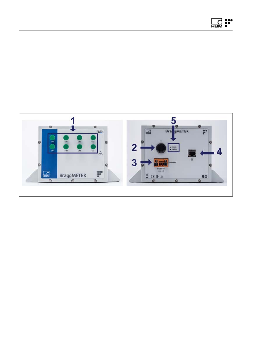
3 Operation
Front view Back view
3.1 Connectors
3.1.1 Standard
Fig. 3.1
The connectors and buttons in Fig. 3.1 are:
1 Optical Output Connectors (FC/APC)
2 ON/OFF Button
3 Power Connector
4 Ethernet Connector
5 POWER and STATUS LEDs
14 A4248-6.0 HBM: public FS22 DI
Page 15
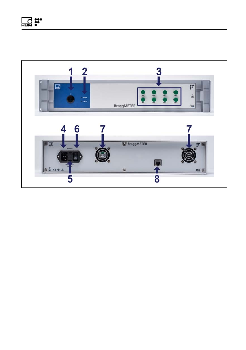
3.1.2 Rack-Mountable
Front view
Back view
Fig. 3.2
Operation
The connectors and buttons in Fig. 3.2 are:
1 ON/OFF Button
2 POWER and STATUS LEDs
3 Optical Output Connectors
4 Power Connector
5 Electric Fuse
6 Safety Power Button
7 Fans
8 Ethernet Connector
FS22 DI A4248-6.0 HBM: public 15
Page 16

Operation
3.2 Setting Up
3.2.1 Power Supply
To start the Industrial BraggMETER DI Standard inter
rogator connect the supplied power adaptor to a 100 240 V power line, or an 11-36 VDC power line directly, to
the interrogator power connector (number 3 in Fig. 3.1).
To start the Industrial BraggMETER DI Rack-Mountable
interrogator connect the supplied power cable from a
100 - 240 V power line to the interrogator (number 4 in
Fig. 3.2) and turn on the safety power button (number 6
in Fig. 3.2).
The interrogator must be used with a dedicated power
supply source and not shared with other equipment.
3.2.2 Optical Connectors
The Industrial BraggMETER DI can be purchased either
with FC/APC, or SC/APC optical connectors. Number 1
in Fig. 3.1 and number 3 in Fig. 3.2 exemplifies FC/APC
connectors.
Attention should be paid to the cleaning of the optical
connectors. A dirty connector can compromise the mea
surement and will degrade the performance of the inter
rogator. It is advisable to frequently clean the connectors
using appropriate tools.
FS22 - Industrial BraggMETER DI can have one, four or
eight optical channels in parallel.
16 A4248-6.0 HBM: public FS22 DI
Page 17

Operation
3.2.3 Ethernet Connection
Connect the Ethernet RJ45 connector directly to a PC
using a Ethernet cross-over cable, or to a network con
nector using a direct Ethernet cable (in this case, the
Industrial BraggMETER DI must be in the same subnet
as your Local Network).
Important
The interrogator default network configuration is
"10.0.0.150:255.0.0.0:0.0.0.0".
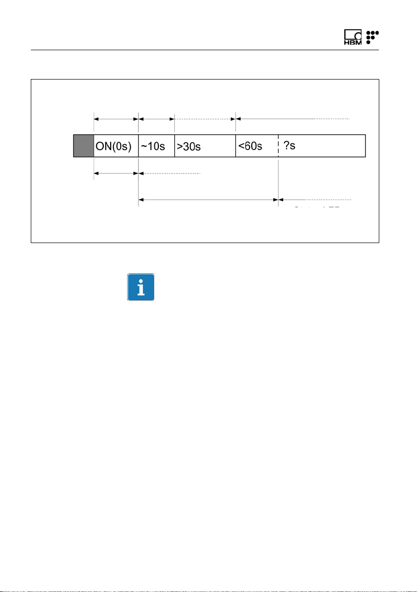
3.3 Switching On
Pressing the “ON/OFF" button (number 2 in Fig. 3.1 or
number 1 in Fig. 3.2) will start the interrogator. The STA
TUS LED (number 5 in Fig. 3.1 or number 2 in Fig. 3.2)
will start blinking at 2 Hz. After approximately 10 seconds
it will start blinking at 1 Hz. This means that the inter
rogator is already on and responsive, but the optoelec
tronic module is still warming up. After approximately
60 seconds it should stay on permanently. This means
that the interrogator is able to measure.
FS22 DI A4248-6.0 HBM: public 17
Page 18
Operation
CorrectWrong
Status LED
Blinking 2 Hz
Status LED
Blinking 2 Hz
Status LED
Blinking 1 Hz
Status LED
Blinking 5 Hz
(initialization issues)
Status LED
Blinking 1 Hz
Status LED
On
Status LED
Blinking 5 Hz
(measurement issues)
Fig. 3.3
Information
If the interrogator does not start correctly, the STATUS
LED will blink faster. If this happens, please contact HBM
FiberSensing technical support.
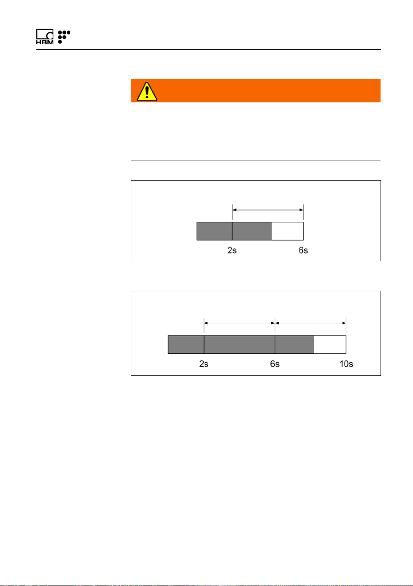
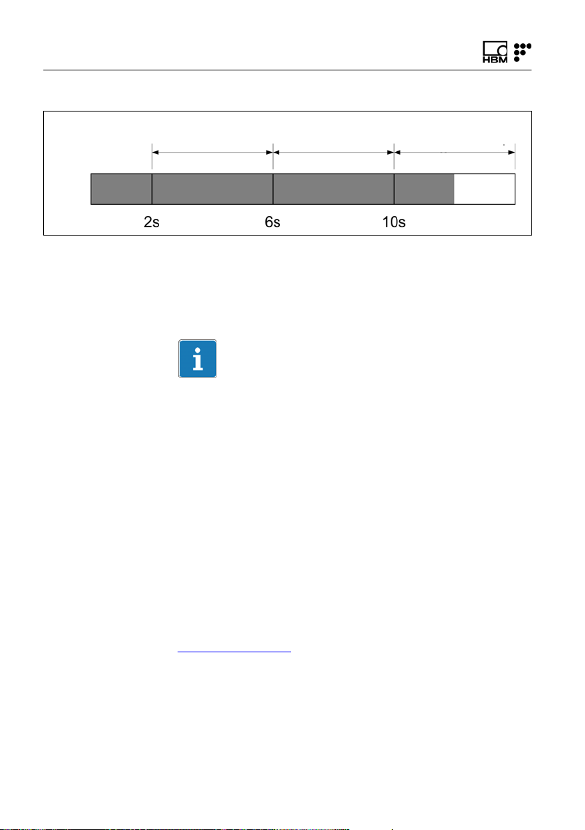
3.4 Switching Off
To avoid accidental shut-down of the interrogator, press
the "ON/OFF" button (number 2 in Fig. 3.1 or number 1
in Fig. 3.2) between 2 and 6 seconds (Fig. 3.4).
If for some reason the 6 seconds are exceeded and the
button is released before 10 seconds are over, the inter
rogator will remain ON (Fig. 3.5).
18 A4248-6.0 HBM: public FS22 DI
Page 19
Operation
WARNING
If the “ON/OFF” button is pressed more than 10 seconds,
changes on the interrogator configuration are performed
and connection might be lost. See section 3.5.2, under
Resetting IP to Default, for further details.
POWER LED
blinking at 1 Hz
Fig. 3.4
POWER LED
blinking at 1 Hz
Fig. 3.5
POWER LED
ON
3.5 Operating the Interrogator
3.5.1 Network Properties
To operate the FS22 - Industrial BraggMETER DI from a
personal computer, the PC network properties should be
set so that both elements are configured in the same
subnet.
FS22 DI A4248-6.0 HBM: public 19
Page 20
Operation
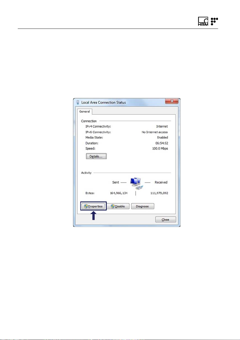
To configure your personal computer so that it is on the
same subnet as the default for the interrogator, proceed
as follows:
► On the control panel choose Network Connections
► Select the LAN connection. The window displayed in
Fig. 3.6 will appear. Click on Properties.
Fig. 3.6
20 A4248-6.0 HBM: public FS22 DI
Page 21
Operation
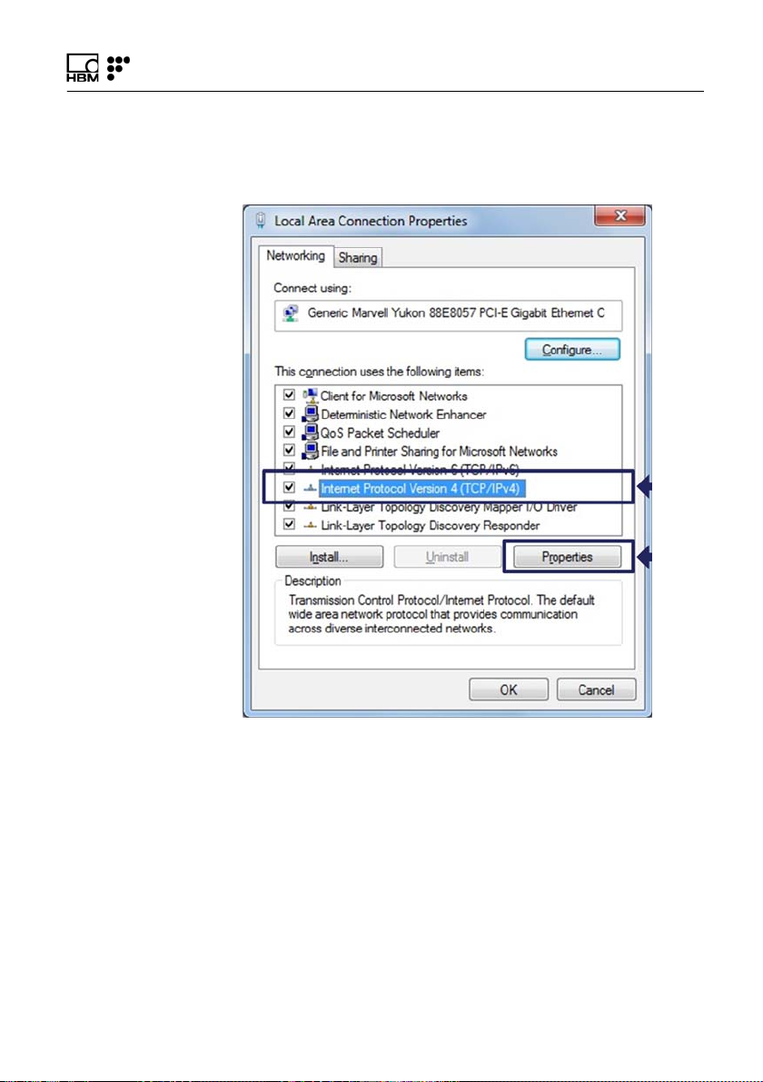
► Select the Internet Protocol (TCP/IP) and click on the
Properties button (Fig. 3.7).
Fig. 3.7
FS22 DI A4248-6.0 HBM: public 21
Page 22
Operation
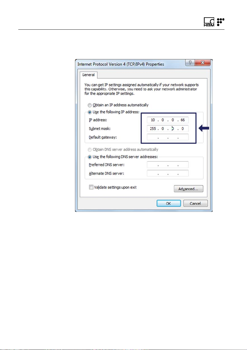
► Set the IP address and the Subnet mask (Fig. 3.8).
Fig. 3.8
► Press OK.
22 A4248-6.0 HBM: public FS22 DI
Page 23

Operation
3.5.2 Interrogator IP Address
Changing IP
The interrogator default network properties are
10.0.0.150:255.0.0.0:0.0.0.0. These can be changed
using the SCPI commands.
The interrogator proceeds with a change of these proper
ties when :SYST:IPAD:N.N.N.N:N.N.N.N:N.N.N.N com
mand is sent. See section 5.1.3 “System commands”
under IP Address for further details.
Information
The definition of the network properties shall comprise
three digits to define each number – e.g.,
010.000.000.150:255.000.000.000:000.000.000.000 –.
Default IP Address
The default network properties of the interrogator are
"10.0.0.150:255.0.0.0:0.0.0.0". These default network
properties cannot be changed.
Resetting IP to Default
If by any chance there is the need to physically change
the IP address of the interrogator, press the "ON/OFF"
button for more than 10 seconds to reset the interrogator.
When the button is being pressed for 10 seconds the
POWER LED blinks 3 times and goes OFF. The "ON/
OFF" button can then be released and the IP Address
will be reset.
This procedure will restart the interrogator automatically.
FS22 DI A4248-6.0 HBM: public 23
Page 24
Operation
POWER LED
blinking at 1 Hz
Fig. 3.9
POWER LED ON POWER LED blinks
3 times and goes OFF
This procedure resets the interrogator changing its IP
address to the default and its measuring settings to the
last ones stored.
Information
The interrogator default network properties are
"10.0.0.150:255.0.0.0:0.0.0.0".
3.5.3 Synchronization
In order to achieve synchronous measurements between
different devices the NTP (Network Time Protocol) syn
chronization via Ethernet must be used.
Each optical Interrogator can synchronize its internal
clock with an NTP server. It is possible to achieve accu
racies of 1ms or higher, depending on whether or not a
dedicated NTP server is being used.
Further information about NTP can be found at
http://www.ntp.org
24 A4248-6.0 HBM: public FS22 DI
Page 25
Single interrogator
Multiple
interrogators
Operation
Measuring systems typology
A measurement system can be as simple as a single
interrogator or a bit more complex with combined inter
rogators with the same or different sampling rates, and
interrogators combined with other equipment.
For the usage of a single interrogator no special synchro
nization is needed.
BraggMONITOR DI software can only operate one inter
rogator at a time. If an NTP server is running on the
same PC as the BraggMONITOR DI, the interrogator
internal clock – hence BraggMONITOR DI – will sync.
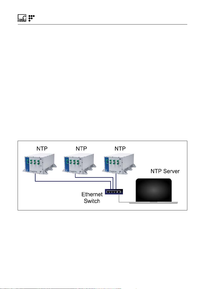
If more than one interrogator is used, synchronization
becomes important and if an NTP server is running the
equipment will start synching as soon as a first communi
cation from the server is received.
Fig. 3.10
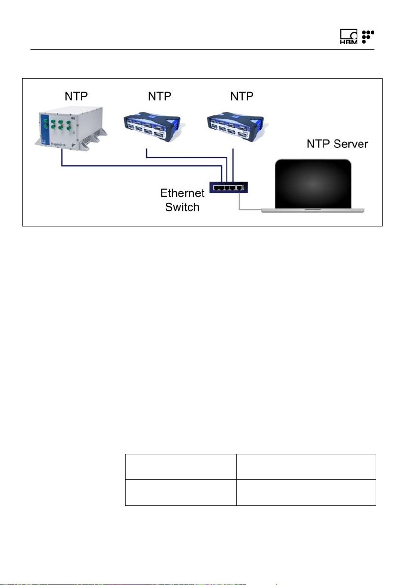
Hybrid
A hybrid measurement system is a system composed by
different equipment types and technologies that can be
operated with different sampling rates. Taking the exam
ple of HBM families a hybrid system could be a combina
tion of Interrogators with QuantumX.
FS22 DI A4248-6.0 HBM: public 25
Page 26
Operation
Fig. 3.11
Synchronization is again of extreme importance in such
systems. When an NTP server is running the Interrogator
will start synching as soon as a first communication from
the server is received.
For details on the other equipment please refer to their
respective user manuals.
Synchronization process
Each interrogator synchronizes its internal clock with the
NTP server. Upon starting, all devices and the NTP
server need some settling time to achieve the best syn
chronism possible.
The following features for NTP synchronization are avail
able:
Number of devices to
be synchronized
Synchronization
accuracy
Unlimited
100 μs to 10 ms
26 A4248-6.0 HBM: public FS22 DI
Page 27

Operation
Synchronization
settling time
Synchronization
master
Up to 30 min during first start,
up to 2 min during restart
External SyncMaster, e.g. PC
For a good synchronization, the dedicated NTP server
should run continuously. The accuracy is described by
the two values:
S Offset: average deviation from time server
S Jitter: typical variation range of the offset value
The clock synchronization is classified using the following
offset intervals:
S <500 μs: excellent
S <1 ms: very good
S <2 ms: good
S <5 ms: acceptable
S <10ms: poor
S >10ms: not acceptable
A successful NTP Sync is achieved if the offset between
the internal clock of the device and the NTP server is
below 5ms.
The quality of the NTP synchronization can be queried
using the SCPI commands (please refer to section “Syn
chronization” on page 53 for further details).
3.5.4 Operation
The FS22 - Industrial BraggMETER DI interrogator can
be fully controlled using standard SCPI syntax com
FS22 DI A4248-6.0 HBM: public 27
Page 28

Operation
mands (for a complete command list, please refer to sec
tion 5.1 “Communication Protocol Syntax” on page 40).
All valid answers to sent commands, start with :ACK.
Whenever there is a misspell or a wrong command sent,
an error message will be returned:
:NACK:INVALID COMMAND
That means that the command does not exist. Check if
the spelling is correct.
:NACK: COMMAND NOT ACCEPTED AT CURRENT
STATUS
It is not possible to execute the command sent at the cur
rent status.
Ask the current status of the interrogator (:STAT?) and
confirm with scheme from Fig. 3.12 to see how to change
it.
:NACK: '?' MUST BE THE LAST CHARACTER
The sent command should have a '?' at the end of the
command string.
Operational States
The FS22 - Industrial BraggMETER DI interrogator has
five operational states:
0 error
The error state corresponds to a malfunction of the opto
electronic module of the FS22 - Industrial BraggMETER
DI interrogator. The system can recover from this state
by resetting.
1 ready
In the ready state, the FS22 - Industrial BraggMETER DI
interrogator is ready to start acquisition.
28 A4248-6.0 HBM: public FS22 DI
Page 29

Operation
2 free acquisition
3 continuous
acquisition
5 warming-up
The free acquisition state enables the FS22 - Industrial
BraggMETER DI interrogator to perform single measure
ments on a specified optical channel. The FS22 - Indus
trial BraggMETER DI interrogator can be configured in
terms of gain, threshold and sampling rate. The corre
sponding configuration can be stored for future refer
ence.
The continuous acquisition state allows continuous wave
length acquisition over all optical channels at 50, 100,
200, 500 or 1000 S/s. The FS22 - Industrial BraggME
TER DI interrogator can also display continuous OSA
trace acquisition every second. For that the sampling rate
of the interrogator shall be set to 50 S/s.
The FS22 - Industrial BraggMETER DI interrogator starts
on the warming-up state that enables the settling of the
operation parameters and recall of the acquisition config
uration.
FS22 DI A4248-6.0 HBM: public 29
Page 30

Operation
Fig. 3.12
Commands for Different Operational States
0 error
In the error state, the FS22 - Industrial BraggMETER DI
interrogator only replies to the commands:
:IDENtification?
:STATus?
1 ready
In the ready state, the FS22- Industrial BraggMETER DI
interrogator replies to common commands:
:IDENtification?
:STATus?
:SYSTem:TIME?
:SYSTem:TIME:HH:MM:SS
30 A4248-6.0 HBM: public FS22 DI
Page 31

2 free acquisition
Operation
:SYSTem:DATE?
:SYSTem:DATE:YYYY:MM:DD
:SYSTem:NTPSync?
:SYST:IPAD:N.N.N.N:N.N.N.N:N.N.N.N
And is also responsive to start acquisition commands:
:ACQUisition:STAR
:ACQUisition:OSATrace:CONTinuous:STARt:X (com
mand is available at 50 S/s only)
:ACQUisition:WAVElength:CONTinuous:STARt
:ACQUisition:WAVElength:CONTinuous:NTP
Sync:STARt
The FS22 - Industrial BraggMETER DI interrogator runs
on the free acquisition state after receiving the :ACQUisi
tion:STARt command. In this state the, FS22 - Industrial
BraggMETER DI interrogator is responsive to all com
mands except:
:ACQUisition:WAVElength:CONTinuous:STARt
:ACQUisition:OSATrace:CONTinuous:STARt:X
:ACQUisition:WAVElength:CONTinuous:NTP
Sync:STARt
:SYSTem:TIME?
:SYSTem:TIME:HH:MM:SS
:SYSTem:DATE?
:SYSTem:DATE:YYYY:MM:DD
:SYST:IPAD:N.N.N.N:N.N.N.N:N.N.N.N
FS22 DI A4248-6.0 HBM: public 31
Page 32

Operation
3 continuous
acquisition
5 warm up
Important
The command :ACQUisition:OSATrace:CONTinu
ous:STARt:CHANnel:X is only available when the sam
pling rate is defined as 50 S/s.
The FS22 Industrial BraggMETER DI interrogator returns
to the ready state through the :ACQUisition:STOP com
mand.
The FS22 - Industrial BraggMETER DI interrogator runs
in the continuous acquisition state after receiving the
commands:
:ACQUisition:OSATrace:CONTinuous:STARt:CHANnel:X
(command is available at 50 S/s only)
:ACQUisition:WAVElength:CONTinuous:STARt
:ACQUisition:WAVElength:CONTinuous:NTP
Sync:STARt
The continuous acquisition commands can only be exe
cuted in the ready state.
In this operational state the FS22 - Industrial BraggME
TER DI interrogator only replies to the commands:
:ACQUisition:STOP
:IDENtification?
:STATus?
After receiving the :ACQUisition:STOP command, the
FS22 - Industrial BraggMETER DI interrogator returns to
the ready state.
In the warm up state, the FS22 - Industrial BraggMETER
DI interrogator only replies to the commands:
:IDENtification?
:STATus?
32 A4248-6.0 HBM: public FS22 DI
Page 33

Operation
Power Shortage
In case of power shortage when the FS22 - Industrial
BraggMETER DI interrogator is running in the ready, free
acquisition or continuous acquisition states, the opera
tional state will maintain the stored acquisition settings
once the power supply is reestablished.
FS22 DI A4248-6.0 HBM: public 33
Page 34

Measuring Examples
4 Measuring Examples
4.1 Typical Configuration
Typically, a fiber Bragg grating Sensing Network is
divided into branches of several sensors connected in
series. Fig. 4.1 shows a scheme of a possible fiber Bragg
grating sensing branch.
FS62 Strain
FS65 Acceleration Strain
Fig. 4.1
FS64 Tilt
A branch can accommodate sensors with wavelengths
corresponding to all standard HBM FS wavelengths. The
number of sensors in a channel can vary if there is previ
ous knowledge about the spectral range the sensors will
cover. The major concern is the overlap of adjacent sen
sors. The available optical channels have simultaneous
acquisition, meaning that the sensing network can have a
large number of fiber Bragg grating sensors interrogated
at the same time.
34 A4248-6.0 HBM: public FS22 DI
Page 35

Measuring Examples
The employed technology allows multi-functionality
meaning that on the same branch it is possible to mea
sure Strain, Temperature, Displacement, Pressure,
Acceleration, etc…
The sensing network can be placed up to 10 km from the
interrogator without significant losses on transmission
over the optical fiber, operating under EM/RF interfer
ences.
Each fiber Bragg grating sensor has a characteristic cen
tral wavelength (λ0) that depends only on the measurand.
This means that with this technology there is no need for
recalibrations every time the system is shut down. The
Industrial BraggMETER DI is a ruggedized interrogator
designed for 24/7 operation.
FS22 DI A4248-6.0 HBM: public 35
Page 36

Measuring Examples
4.1.1 HBM FS Wavelengths
The HBM FiberSensing standard wavelengths are:
FS Line OP Line
Central wavelength (nm)
N - 1503.3 1520
O - 1509.7 1525
K - 1516.1 1530
L - 1522.5 1535
A - 1528.9 1540
B - 1535.1 1545
C - 1541.5 1550
D - 1547.9 1555
E - 1554.3 1560
F - 1560.8 1565
G - 1567.2 1570
H - 1573.8 1575
I - 1580.2
J - 1586.6
36 A4248-6.0 HBM: public FS22 DI
Page 37

Measuring Examples
4.2 Definitions and Operation Methods
The following definitions are applicable to this equipment
only.
4.2.1 Wavelength
The Wavelength value corresponds to the wavelength at
the peak of the fiber Bragg grating reflection spectrum,
commonly referred as Bragg wavelength (Fig. 4.2).
FBG reflection spectrum
Wavelength
Power
Wavelength in nm
Fig. 4.2
FS22 DI A4248-6.0 HBM: public 37
Page 38

Measuring Examples
4.2.2 Power
The Power value corresponds to the optical power
reflected by the fiber Bragg grating at the peak wave
length (Fig. 4.3). It is a relative value from 0 to 4095.
FBG reflection spectrum
Power
Power
Wavelength in nm
Fig. 4.3
38 A4248-6.0 HBM: public FS22 DI
Page 39

Measuring Examples
4.2.3 Gain
The gain is an amplification value applied to the received
reflected signal in order to optimize the measured power.
It is a value from 0 to 255.
FBG reflection spectrum with Gain = 10
Power
FBG reflection spectrum
with Gain = 0
Wavelength in nm
Fig. 4.4
FS22 DI A4248-6.0 HBM: public 39
Page 40

Measuring Examples
Power
4.2.4 Threshold
The threshold value corresponds to the considered
power level for the FBG peak computation and can be
used to disregard side lobes and ground noise. It is a
value from 200 to 3200 definable for each optical channel
individually. It is measured bottom-up from the 0 (zero)
power value.
FBG reflection spectrum
Detected peaks
Disregarded peak
Threshold
Wavelength in nm
Fig. 4.5
40 A4248-6.0 HBM: public FS22 DI
Page 41

Measuring Examples
4.3 Common Measuring Difficulties
There may be the possibility of having measuring mal
functions due to problems in the sensing network or opti
cal connections. A list of some of the usual problems is
described below with the explanation for their occurrence
and correction.
4.3.1 Dirty Connector
It is very important that the connectors are cleaned prior
to any connection. Otherwise, dust and moister can be
deposited in the interrogator's optical adaptors, which will
compromise measurements. In Fig. 4.6 a picture of a
magnified connector is presented. The dark gray circle
corresponds to the fiber cladding and the small light gray
circle is the core of the fiber. One picture of a clean con
nector and one picture of a dirty connector are pre
sented.
Clean connector
Fig. 4.6
Dirty connector
The most common effect of dirt on the connections is a
large amount of broad band light being reflected at the
connection, in both directions, meaning that the dynamic
range for measurements becomes smaller.
FS22 DI A4248-6.0 HBM: public 41
Page 42

Measuring Examples
Power
clean connector trace
dirty connector trace
dynamic range
reduction
Wavelength in nm
Fig. 4.7
To clean an optical interrogator adapter, use an appropri
ate cotton swab (there are several cleaning swabs in the
market frequently used for telecom fibers) embedded in
isopropyl alcohol. Insert it in the optical adapter as in
Fig. 4.8 and rotate the swab always in the same direc
tion.
Fig. 4.8
42 A4248-6.0 HBM: public FS22 DI
Page 43

Measuring Examples
4.3.2 Broken Connector
It may also occur that the interrogator adapter sleeve
breaks. In this case, when an optical connector is
inserted, it will not get proper alignment and measure
ments will be compromised. A broken sleeve will look as
shown in Fig. 4.9.
Fig. 4.9
To solve this problem you should contact HBM
FiberSensing.
4.3.3 Reflective Fiber Ending
Even when all connections have been performed cor
rectly, it may occur that the interrogator does not find any
sensor on an array. One of the reasons may be the
excess of reflected light saturating the detectors.
When a fiber is perfectly cut (Fig. 4.10 on the left), a
large amount of light is reflected right back to the fiber
core in the right direction, heading to the interrogator
detectors. When this occurs, an index matching gel or an
angled termination must be used. If these are unavail
able, the tip of the fiber can be smashed with a metallic
tool. This will destroy the perfect geometry (Fig. 4.10 on
the right) and the light that is reflected at the surface will
take random directions ending up outside the core.
FS22 DI A4248-6.0 HBM: public 43
Page 44

Measuring Examples
Reflective Fiber Ending
Fig. 4.10
4.3.4 Cut Fiber
When the fiber, for any reason, is broken between two
sensors in series, the sensors that are after the fault may
disappear from the optical spectrum and may not be
detected.
There may also be the case that the fiber is cut, but not
completely spread apart (e.g. the fiber is damaged in an
area covered with glue). This will cause a Fabry-Pérot
effect – the light will suffer multiple reflections inside the
cavity creating sinusoidal background reflection.
Fig. 4.11 shows a schematic representation of the
reflected spectrum for the three presented cases.
Refractive Fiber Ending
44 A4248-6.0 HBM: public FS22 DI
Page 45

Measuring Examples
Fig. 4.11
FS22 DI A4248-6.0 HBM: public 45
Page 46

Measuring Examples
4.3.5 Fuse Failure
Electrical shorts on the power supply may cause prob
lems to the interrogators. The Industrial BraggMETER DI
on its RackMountable format is directly connected to the
100240 V power line meaning that it has no external pro
tection. Replaceable fuses are available on the interroga
tor's backside next to the power connector (number 5 in
Fig. 3.2). To replace the fuses, release the top and bot
tom springs of the fuses’ support (Fig. 4.12) and then
remove the piece (Fig. 4.13).
Fuse characteristics:
S Rated voltage: 250 Volt AC
S Interrupting rate: 2 Ampere
S Number of fuses: 2
Fig. 4.12
46 A4248-6.0 HBM: public FS22 DI
Page 47

Measuring Examples
Fig. 4.13
The Standard format of the interrogator is powered at
1136 VDC, which means that the electrical protection
should be granted by the power source or the adapter. If,
by any chance, the power supply is overcome, the inter
rogator might be damaged and needs repair at HBM
FiberSensing.
FS22 DI A4248-6.0 HBM: public 47
Page 48

Remote Communications
5 Remote Communications
5.1 Communication Protocol Syntax
The interrogator is controlled using standard SCPI syntax
commands.
5.1.1 Command Syntax
Each command is an ASCII string with arguments sepa
rated by ":" followed by the carriage return "\r" and line
feed "\n".
Fig. 5.1
Communication on FS22 - Industrial BraggMETER DI is
made via port 3500. Continuous data streaming is
received via port 3365.
48 A4248-6.0 HBM: public FS22 DI
Page 49

Remote Communications
The commands for the FS22 - Industrial BraggMETER DI
have the following correspondence:
X Optical
Channel
S Sensor Integer.
T Threshold Integer. From 200 to 3200.
G Gain Integer. From 0 to 255.
R Sampling
Rate
N Number Integer.
HH:MM:SS Time Integer.
YYYY:MM:DD Date Integer.
Q NTP Quality Integer.
String.
Integer to:
FS22 Single Channel : 0.
FS22 Quad Cahnnel: 0 to 3.
FS22 Octo Channel: 0 to 7.
Character:
A.
Integer. Valid Sampling Rates: 1000, 500,
200, 100, 50 (S/s).
HH – hour
MM – minutes
SS – seconds
YYYY – year
MM – month
DD – day
0 for “Not acceptable”
1 for “Acceptable”.
FS22 DI A4248-6.0 HBM: public 49
Page 50

Remote Communications
5.1.2 Common Commands
Identification
Store configuration
Recall
:IDEN?
Queries the FS22 - Industrial BraggMETER DI interrogator
type and firmware revision. The return string is a list sepa
rated by ":" consisting of Manufacturer, Unit Name and Revi
sion, Number of Channels, Serial Number and Date.
Example:
Command :IDEN?
Answer :ACK:HBM FiberSensing:FS22DI
v2.0:08:046 840 200 188:20150202
Configuration
:STOR
Stores FS22 - Industrial BraggMETER DI interrogator acqui
sition settings to the internal configuration file. The gain and
threshold values of each channel are stored. This command
can only be executed in the free acquisition state (see sec
tion Operational States for state description).
Example:
Command :STOR
Answer :ACK
:RECA
Recalls previously saved FS22 - Industrial BraggMETER DI
interrogator settings from the internal configuration file. The
command restores the gain and threshold values of each
channel of the FS22 - Industrial BraggMETER DI interrogator
to the values previously stored in the configuration file.
Example:
Command :RECA
Answer :ACK
50 A4248-6.0 HBM: public FS22 DI
Page 51

Status
Remote Communications
Status query
Time query
:STAT?
Queries the operation condition status of the FS22 - Indus
trial BraggMETER DI interrogator. Returns the current status
of the instrument:
0 error;
1 ready;
2 free acquisition;
3 continuous acquisition;
5 warming up.
Example:
Command :STAT?
Answer :ACK:2
5.1.3 System Commands
Time
:SYST:TIME?
Queries the FS22 - Industrial BraggMETER DI interrogator
time.
The interrogator returns hours, minutes and seconds sepa
rated by ":".
Example:
Command :SYST:TIME?
Answer :ACK:15:33:56
FS22 DI A4248-6.0 HBM: public 51
Page 52

Remote Communications
Time setting
Date query
Date setting
:SYST:TIME:HH:MM:SS
Sets the FS22 - Industrial BraggMETER DI interrogator time.
Sent format must be hours, minutes and seconds separated
by ":".
Example:
Command :SYST:TIME:14:26:10
Answer :ACK
Date
:SYST:DATE?
Queries the FS22 - Industrial BraggMETER DI interrogator
date.
The interrogator returns the year, month and day separated
by ":".
Example:
Command :SYST:DATE?
Answer :ACK:2011:09:23
:SYST:DATE:YYYY:MM:DD
Sets the FS22 - Industrial BraggMETER DI interrogator date.
Sent format must be year, month and day separated by ":".
Example:
Command :SYST:DATE:2011:09:23
Answer :ACK
52 A4248-6.0 HBM: public FS22 DI
Page 53

Synchronization
Remote Communications
NTP query
IP setting
:SYST:NTPS?
Queries for the NTP synchronization status. Retrieves infor
mation on three parameters separated by “:”
Q: NTP Quality:
0 = not acceptable if offset >= 10ms;
1 = acceptable if offset <10ms.
Offset: time difference in milliseconds between the server
clock and host clock.
Jitter: time difference in milliseconds between 2 samples.
Example:
Command :SYST:NTPS?
Answer :ACK:1:0.489:0.345
IP Address
:SYST:IPAD:N.N.N.N:N.N.N.N:N.N.N.N
Changes FS22 - Industrial BraggMETER DI interrogator IP
address, subnet mask and gateway. Address description
must have three characters to define each number. After this
command is successfully executed the FS22 will restart
automatically. The gateway content of this command (the
last set of N.N.N.N) is optional.
Example:
Command :SYST:IPAD:010.000.000.134:255.000.
000.000:000.000.000.000
Answer :ACK
FS22 DI A4248-6.0 HBM: public 53
Page 54

Remote Communications
5.1.4 Acquisition Commands
Aquisition start
Aquisition stop
Gain setting
:ACQU:STAR
Starts the acquisition of the fiber Bragg grating sensors in all
channels of the FS22 - Industrial BraggMETER DI. This
command can only be executed in the ready state (see sec
tion Operational States for state description).
Example:
Command :ACQU:STAR
Answer :ACK
:ACQU:STOP
Stops all types of acquisition of the fiber Bragg grating sen
sors in all channels of the FS22 - Industrial BraggMETER DI,
returning to the ready state.
Example:
Command :ACQU:STOP
Answer :ACK
Configuration
:ACQU:CONF:GAIN:CHAN:X:G
Sets the detection gain in the X channel of the FS22 - Indus
trial BraggMETER DI interrogator. The gain is a value from 0
to 255.
Example:
Command :ACQU:CONF:GAIN:CHAN:0:3
Answer :ACK
54 A4248-6.0 HBM: public FS22 DI
Page 55

Remote Communications
Gain query
Threshold setting
Threshold query
:ACQU:CONF:GAIN:CHAN:X?
Queries the detection gain in the X channel of the FS22 Industrial BraggMETER DI interrogator. The returned gain
value can range from 0 to 255.
Example:
Command :ACQU:CONF:GAIN:CHAN:0?
Answer :ACK:3
:ACQU:CONF:THRE:CHAN:X:T
Sets the threshold value for the peak detection algorithm in
the X channel of the FS22 - Industrial BraggMETER DI. The
threshold is a value from 200 to 3200.
Example:
Command :ACQU:CONF:THRE:CHAN:0:1000
Answer :ACK
:ACQU:CONF:THRE:CHAN:X?
Queries the threshold value for the peak detection algorithm
in the X channel of the FS22 - Industrial BraggMETER DI.
The threshold is a value from 200 to 3200.
Example:
Command :ACQU:CONF:THRE:CHAN:0?
Answer :ACK:1000
Rate setting
:ACQU:CONF:RATE:R
Sets the sampling rate value R of the FS22 - Industrial
BraggMETER DI for all channels. The sampling rate can
assume the following values: 1000, 500, 200, 100, 50 (S/s).
This parameter is automatically stored in the interrogator.
Example:
Command :ACQU:CONF:RATE:500
Answer :ACK
FS22 DI A4248-6.0 HBM: public 55
Page 56

Remote Communications
Rate query
Wavelength
acquisition
:ACQU:CONF:RATE:R?
Queries the sampling rate value of the FS22 - Industrial
BraggMETER DI. The sampling rate can assume the follow
ing values: 1000, 500, 200, 100, 50 (S/s).
Example:
Command :ACQU:CONF:RATE?
Answer :ACK:200
Free Acquisition
:ACQU:WAVE:CHAN:X?
Returns the peak wavelengths of the fiber Bragg grating
sensors in channel X of the FS22 - Industrial BraagMETER DI
interrogator according to the threshold settings. The central
wavelength values for different fiber Bragg sensors are separ
ated by a comma ",", the row of values ends with carriage
return "\r" and line feed "\n". The number of channels can be
"A" to retrieve the wavelength of all sensors in all channels
simultaneously. Wavelengths are presented in ascending
values.
Example:
Command
Answer
:ACQU:WAVE:CHAN:0?
:ACK:1560.0732,1554.9894,1547.8012,
1540.0954
56 A4248-6.0 HBM: public FS22 DI
Page 57

Remote Communications
Power aquisition
:ACQU:POWE:CHAN:X?
Queries the optical peak power of the fiber Bragg gratings in
channel X. Returns a value between 0 and 4095 for each
sensor on the channel. If the optical channel is saturated, a
value of 4095 will be returned. The peak power values for
different fiber Bragg sensors are separated by a comma ",",
the row of values ends with carriage return "\r" and line feed
"\n". The FS22 - Industrial BraggMETER DI does not reply, if
no sensor is detected. The number of channels can be "A" to
retrieve the power of all the sensors in all the channels
simultaneously.
Example:
Command :ACQU:POWE:CHAN:0?
:ACK:3875,3622,3161,3240
FS22 DI A4248-6.0 HBM: public 57
Page 58

Remote Communications
The following command is only available when the acqui
sition rate is set as 50 S/s.
Information
OSA acquisition
:ACQU:OSAT:CHAN:X?
Acquires the optical spectrum trace in the channel X of the
FS22 Interrogator. The acknowledged and data reply to this
command is sent through port 3500. The optical spectrum
trace reply is a list of power values and a list of wavelength
values separated by ":".There is a direct correspondence
between each power value and each wavelength value. The
wavelength data is sorted in descending order. Each power
value in arbitrary units is represented by a set of three hexa
decimal digits. For example, the value D13 represented with
hexadecimal digits corresponds to a power value of 3347 in
decimal notation. The wavelength values are separated by
"," and written in decimal notation (with 4 decimal digits and
"." for decimal separation). The reply string is terminated with
the carriage return "\r" and line feed "\n" characters. This
command can only be executed in the ready state with the
acquisition rate set to 50 S/s (see section 3.5.3 “Operation”,
subsection Operational States for state description).
Example:
Command :ACQU:OSAT:CHAN:1?
Answer Port 3500:
:ACK:...D13D03FA0B98...:...1563.1333,
1563.1194,1563.1054,1563.0915...\r\n
58 A4248-6.0 HBM: public FS22 DI
Page 59

Continuous Acquisition
Remote Communications
Continuous OSA
acquisition
:ACQU:OSAT:CONT:STAR:CHAN:X
Continuously acquires the optical spectrum trace in the
channel X of the FS22 interrogator. The acknowledged reply
to this command is sent through port 3500 while data is sent
through port 3365. The optical spectrum trace reply is a list
of power values and a list of wavelength values separated
by ":".There is a direct correspondence between each power
value and each wavelength value. The wavelength data is
sorted in ascending order. Each power value in arbitrary
units is represented by a set of three hexadecimal digits. For
example, the value D13 represented with hexadecimal digits
corresponds to a power value of 3347 in decimal notation.
The wavelength values are separated by "," and written in
decimal notation (with 4 decimal digits and "." for decimal
separation). The power and wavelength values are updated
every second. The consecutive data reply strings are termi
nated with the carriage return "\r" and line feed "\n" charac
ters. This command can only be executed in the ready state
with the acquisition rate set to 50 S/s (see section 3.5.3
“Operation”, subsection Operational States for state descrip
tion).
Example:
Command :ACQU:OSAT:CONT:STAR:CHAN:1
Answer Port 3500:
:ACK
Port 3365:
:...D13D03FA0B98...:...1563.1333,1563
.1194,1563.1054,1563.0915...\r\n
FS22 DI A4248-6.0 HBM: public 59
Page 60

Remote Communications
Continuous wave
length acquisition
:ACQU:WAVE:CONT:STAR
Continuous acquisition of the peak wavelengths of the fiber
Bragg grating sensors in all channels of the FS22 - Industrial
BraggMETER DI interrogator. Wavelength data is is sent
continuously with updated time data at every second.
On each second one data packet with time stamp informa
tion is sent, followed by the n data packets corresponding to
each sample within that second.
Each time stamp data packet starts with ":" followed by the
date and time with the format «YYYY.MM.DD:HH.MM.SS».
Sample data packets also start with ":" and the central wave
length values for different fiber Bragg sensors are separated
by a comma ",", being the information corresponding to dif
ferent channels separated by ":". The row of values is termi
nated by carriage return "\r" and line feed "\n". This com
mand can only be executed in the ready state (see sec
tion 3.5.4 “Operation”, subsection Operational States for
state description).
Example:
Command :ACQU:WAVE:CONT:STAR
Answer Port 3500:
:ACK
Port 3365:
:1554.9891,1560.0732:1547.8027:::
:TS:2017:02.20:11.13.25
:1554.9897,1560.0741:1547.8030:::
:1554.9894,1560.0727:1547.8029:::
:1554.9893,1560.0732:1547.8027:::
60 A4248-6.0 HBM: public FS22 DI
Page 61

Remote Communications
Continuous Wave
length Acquisition
with Binary Data
:ACQU:WAVE:CONT:NTP:STAR
Continuous acquisition of wavelengths of all the channels of
the interrogator. This command is sent via port 3500 and
corresponding data is received through port 3365. The
received data is in binary format and contains information on
Timestamp, Wavelength values of all sensors from all optical
channels with the following structure:
1) Fixed Header (30 bytes) [always sent independently of
the payload content (even without sensors)]:
a) 2 bytes (sync “#0”)
b) 4 bytes (remaining header length 24 bytes + payload
length)
c) 8 bytes (timestamp):
- LWORD1: seconds since 1.1.1970
- LWORD2: fraction of current second mapped to an
integer range of 32 bit (i.e. 0.5 s would correspond
to ½*2^32)
d) 2 bytes #sensors CH0 + 2 bytes #sensors CH1 + 2
bytes #sensors CH2 + 2 bytes #sensors CH3 + 2 bytes
#sensors CH4 + 2 bytes #sensors CH5 + 2 bytes
#sensors CH6 + 2 bytes #sensors CH7
2) Payload:
a) Payload on interrogator with 1 optical channel:
4 bytes CH0/wvl0 + 4 bytes CH0/wvl1 + (…)
b) Payload on interrogator with 4 optical channels:
4 bytes CH0/wvl0 + 4 bytes CH0/wvl1 + (…) +
CH3/wvl0 + CH3/wvl1 + (…)
c) Payload on interrogator with 8 optical channels:
4 bytes CH0/wvl0 + 4 bytes CH0/wvl1 + (…) +
CH7/wvl0 + CH7/wvl1 + (…)
with wavelengths in ascending order [wvl0 < wvl1 < (…) ].
FS22 DI A4248-6.0 HBM: public 61
Page 62

Remote Communications
Example:
Command :ACQU:WAVE:CONT:NTPS:STAR
Answer Port 3500 » :ACK
Port 3365 »
62 A4248-6.0 HBM: public FS22 DI
Page 63

BraggMONITOR DI Software Details
6 BraggMONITOR DI Software Details
6.1 Software Version
This document refers to BraggMONITOR DI Software
version v1.7.
6.2 Install and Uninstall Software
6.2.1 System Requirements
To operate the current version of BraggMONITOR, your
PC must have the following requirements:
S Intel Pentium or equivalent processor upwards from
1 GHz
S Windows® XP (32 Bit and 64 Bit versions), Windows
Vista® (32 and 64 Bit versions), Windows® 7 (32 Bit
and 64 Bit versions, Home, Professional or Ultimate
editions) or Windows® 8/8.1 (32 Bit and 64 Bit ver
sions) or Windows° 10 (32 Bit and 64 Bit versions)
S Main memory (RAM):
- at least 512 Mbyte for Windows® XP
- at least 1,024 Mbyte for Windows Vista®
- at least 2,048 Mbyte for Windows®7 or higher
S Graphics card (and screen) with a resolution of
1,024 x 768 pixel or higher
S Approx. 1 GByte of free storage capacity for the pro
gram installation; at least a further 1 GByte is needed
FS22 DI A4248-6.0 HBM: public 63
Page 64

BraggMONITOR DI Software Details
for the temporary storage of data; however you can
also use a different drive for this.
S Ethernet interface (100/1000 MBit)
The above requirements are sufficient if you use low
sample rates and some sensors. You must use a more
powerful PC if you wish to use a large number of sensors
with high sample rates.
Information
Using windows display settings with the size of text not
set to 100% might compromise the correct visualization
of BraggMONITOR DI software.
6.2.2 Software Installation
To install HBM FiberSensing BraggMONITOR DI Soft
ware on a PC, please follow the described steps:
► Insert the provided disk with software in the PC;
► Run Setup.exe;
Information
When the operating system is Windows Vista or higher,
open setup.exe as an Administrator with a right-click
(see Fig. 6.1).
64 A4248-6.0 HBM: public FS22 DI
Page 65

BraggMONITOR DI Software Details
Fig. 6.1
► Follow the described steps and press finish.
The installation is now completed. You will need to
restart the computer before using the application.
6.2.3 Software Uninstall
To uninstall the application use the Add and Remove pro
grams tool in Windows
► Go to the Control Panel
► Select Programs and Features
► Select BraggMONITOR DI Software
► Click Uninstall/Change Option and follow the steps.
6.3 Running the Software
6.3.1 Network Properties
To operate the interrogator, the PC network properties
should be set so that both elements are configured in the
same subnet.
FS22 DI A4248-6.0 HBM: public 65
Page 66

BraggMONITOR DI Software Details
To configure your personal computer so that it is on the
same subnet as the default for the interrogator, proceed
as described on section 3.5.1 “Network Properties" on
page 19.
6.3.2 Run as Administrator
The BraggMONITOR DI Software should run with full
administrator privileges. To have these privileges when
the operating system is Windows Vista or higher, rightclick the BraggMONITOR DI Software icon and then
select the "Run as administrator" option (see Fig. 6.2).
To configure the application to always open with Adminis
trator privileges, right-click on the software icon and
select "Properties > Compatibility". Check the box "Run
this program as administrator" (see Fig. 6.2).
66 A4248-6.0 HBM: public FS22 DI
Page 67

BraggMONITOR DI Software Details
Fig. 6.2
FS22 DI A4248-6.0 HBM: public 67
Page 68

BraggMONITOR DI User Interface
7 BraggMONITOR DI User Interface
The BraggMONITOR DI Software graphical interface is
divided in two different areas (Fig. 7.1):
1 General Bar
2 Graphical Area
Fig. 7.1
68 A4248-6.0 HBM: public FS22 DI
Page 69

BraggMONITOR DI User Interface
7.1 General Bar
The General Bar, which is always active, is where the
main acquisition actions can be performed.
The current date and time are shown on the left (num
ber 1 in Fig. 7.2).
Before starting acquisition, it is necessary to establish
connection between the interrogator and the software.
For that, press the “connect” button (number 2 in
Fig. 7.2). If the software finds the device, the “connect”
button changes to “disconnect", as shown in Fig. 7.3, and
the “start” button (number 3 in Fig. 7.2) becomes active.
Fig. 7.2
Fig. 7.3
If a interrogator is not found in the previously used IP
Address, a window will pop up (Fig. 7.4) and a new IP
Address has to be defined (number 1 in Fig. 7.4), tested
(number 2 in Fig. 7.4) and confirmed (number 3 in
Fig. 7.4) by the user.
FS22 DI A4248-6.0 HBM: public 69
Page 70

BraggMONITOR DI User Interface
Fig. 7.4
Information
The FS22 – Industrial BraggMETER DI interrogators
default IP is 10.0.0.150 which is the IP Address used in
the first connection with the BraggMONITOR DI Soft
ware.
7.1.1 Acquisition
Start Acquisition
Press the “start” button (number 3 in Fig. 7.2) to start
acquisition. This will start the acquisition and representa
tion of the measured values for all optical channels. The
button will change from start to stop status (Fig. 7.5).
Fig. 7.5
70 A4248-6.0 HBM: public FS22 DI
Page 71

BraggMONITOR DI User Interface
Information
Before starting acquisition make sure that the network
configuration on «Configuration» tab is up to date. For
more details refer to section 7.2.5, page 81.
Save Data
To start saving data, select the file path to define the
folder where data is to be stored (see section 7.2.3,
page 78).
The naming of the file is automatic and corresponds to
the timestamp of the last measurement recorded (ex.
BraggMONITOR DI Data [2015.07.16.14.48.40;
2015.07.16.14.49.06].txt).
Saved data file collects the data between the instant the
save button is pressed and the instant it is pressed back.
Data files are divided in accordance to a predefined max
imum size. To define the maximum size of the data files,
see section 7.2.5, page 81.
The first row of data files indicates the acquisition rate
and the second row indicates the columns meaning. The
data file is organized in columns as follows, see Fig. 7.6.
1 1st column – UTC Date: «DD-MM-YYYY»
nd
2 2
column – UTC Time: «HH:MM:SS.SSS»
rd
3 3
column – Sample: Sample number
4 Following columns – Sensor Name (Formula): mea
sured values (formula computed) ordered by optical
channel, then by wavelength.
FS22 DI A4248-6.0 HBM: public 71
Page 72

BraggMONITOR DI User Interface
Fig. 7.6
Open Data in Microsoft Excel
To import the data file to a Microsoft Office Excel Work
book proceed as follows:
Once Microsoft Excel is opened, press button “From
Text" from menu Data>Get External Data (see Fig. 7.7)
and select the file data file.
Fig. 7.7
Then it is necessary to complete text import wizard. All
options must be set as shown in Fig. 7.8, Fig. 7.9,
Fig. 7.10, Fig. 7.11 and Fig. 7.12.
72 A4248-6.0 HBM: public FS22 DI
Page 73

Fig. 7.8
BraggMONITOR DI User Interface
Fig. 7.9
FS22 DI A4248-6.0 HBM: public 73
Page 74

BraggMONITOR DI User Interface
Fig. 7.10
Fig. 7.11
74 A4248-6.0 HBM: public FS22 DI
Page 75

BraggMONITOR DI User Interface
Fig. 7.12
Stop Acquisition
To stop acquisition, press the “stop” button (number 3 in
Fig. 7.2).
7.1.2 Software and Interrogator Information
General information about the software and the inter
rogator can be displayed by pressing the “info" button
(number 5 in Fig. 7.2).
7.1.3 Exit Application
To exit BraggMONITOR DI Software application, press
the “exit” button (number 6 in Fig. 7.2).
7.2 Graphical Area
The graphical area is divided into six tabs:
S Graphical View
S Numerical View
S Spectral View
S FFT View
FS22 DI A4248-6.0 HBM: public 75
Page 76

BraggMONITOR DI User Interface
S Configuration
S SCPI Interface
7.2.1 Graphical View
On the Graphical View, graphical representation of 1000
measured values can be found every second (number 1
in Fig. 7.13).
Fig. 7.13
Select the sensors to be displayed using the drop-down
arrow next to the legend (number 2 in Fig. 7.13). Tick the
channel box to enable or disable their representation.
76 A4248-6.0 HBM: public FS22 DI
Page 77

BraggMONITOR DI User Interface
Zoom In and Zoom Fit
To adjust the graphical representation, use the zoom in
and zoom fit functions. Zoom in by selecting an area on
the displayed graph and zoom fit by pressing number 3 in
Fig. 7.13. Alternatively, scale numbers can be edited.
Clear Graph
All displayed data can be deleted from the graph by
pressing the “clear” button (number 4 in Fig. 7.13).
7.2.2 Numerical View
The Numeric View shows the acquired values (in accor
dance to the configuration formula - see table Tab. 7.1 on
page 85) for each optical channel, organized in columns
as in Fig. 7.14.
Fig. 7.14
FS22 DI A4248-6.0 HBM: public 77
Page 78

BraggMONITOR DI User Interface
7.2.3 Spectral View
The Spectral View tab is only accessible when data
acquisition is stopped.
This tab represents the spectral response of the sensors
connected to the interrogator. The full spectrum contains
approx. 7020 data points corresponding to the reflected
optical power in dBm from 1500 nm to 1600 nm with an
approx. 15 pm sampling resolution (number 1 in
Fig. 7.15). For each detected FBG peak the pair of wave
length and power values are represented in a table for
mat (number 10 in Fig. 7.15)
Fig. 7.15
The Spectral View can only represent one channel at a
time. Channel selection can be performed on number 9 in
Fig. 7.15.
78 A4248-6.0 HBM: public FS22 DI
Page 79

Gain
Threshold
BraggMONITOR DI User Interface
The number of FBGs identified in the selected channel is
represented in number 11 in Fig. 7.15.
Information
The number of detected peaks per channel is limited in
accordance to the sampling rate. In case there are more
peaks than the limit, the lower wavelengths will be elimi
nated from the list.
Measurement Configuration
Measurement settings can influence sensor readings.
Gain and Threshold values should be defined according
to the FBG sensing network status, so that peak ampli
tude is around 3000 and no FBG side lobes are detected
as peaks. These settings can be configured indepen
dently for each optical channel.
Gain is directly related to the optical power used on the
measurement of the optical channel. The gain value
should be raised to overcome losses on the network.
Gain is an integer value between 0 and 255. The current
gain value can be found using the get gain button (num
ber 3 in Fig. 7.15). The gain value is updated every time
the Spectral View tab is selected or a new channel is
defined. To define a new gain value, write it on the gain
box (number 4 in Fig. 7.15) and press “set gain” button
(number 5 in Fig. 7.15).
Threshold defines the line between usable signals and
noise. It is an integer value between 200 and 3200.
Operations for getting and defining threshold values can
be performed on a similar way to the gain, but using the
threshold buttons (number 6, 7 and 8 in Fig. 7.15). The
threshold value is updated every time the Spectral View
tab or a new channel are selected. This value is also rep
FS22 DI A4248-6.0 HBM: public 79
Page 80

BraggMONITOR DI User Interface
resented graphically as a horizontal line on the power bar
graph.
7.2.4 FFT View
FFT View tab shows the Fast Fourier Transform (FFT)
graph of the acquired measurements. This computation
is based on a predefined FFT function, considering the
measured values exponential weighted (with no averag
ing), being the latest signals more significant for the cal
culations.
Once the “start” button is pressed, all previous measure
ments are erased from the FFT temporary memory. FFT
is shown for the active sensors on the sensors list (num
ber 4 in Fig. 7.16) as defined on the Graphical View tab.
This list of sensors cannot be edited on the FFT View
tab. To enable/disable any sensor, tick the sensor tick
box.
Information
To choose sensors that are not present in the sensors
list, edit the list on the Graphical View tab.
80 A4248-6.0 HBM: public FS22 DI
Page 81

Fig. 7.16
BraggMONITOR DI User Interface
7.2.5 Configuration
Acquisition configuration allows sensors' configuration for
the acquisition of engineering values to be performed. To
accomplish this step correctly, the sensors' calibration
sheets might be needed.
The BraggMONITOR DI allows editing, saving and open
ing sensor configurations. The configuration corresponds
to the identification and the definition of the calibration
formula that converts measured wavelengths into engi
neering values of the sensors.
The easiest way to start measuring and creating a config
uration is to perform an auto-scan (refer to section
«AutoScan» on page 82).
FS22 DI A4248-6.0 HBM: public 81
Page 82

BraggMONITOR DI User Interface
Fig. 7.17
Clear Configuration
If an old configuration is set, it is possible to clear it and
start a new configuration by pressing the “new” button
(number 8 in Fig. 7.17). Be aware this operation will dis
card all previous unsaved configurations of all channels.
AutoScan
When autoscan (number 2 in Fig. 7.17) is performed for
the first time, the interrogator executes a measuring
sweep and the BraggMONITOR DI defines a new config
uration with all the found sensors. This configuration sets
the current measured wavelength as central wave
length (λ0) with a default range of 2.5 nm.
82 A4248-6.0 HBM: public FS22 DI
Page 83

BraggMONITOR DI User Interface
Important
Confirm that gain and threshold values are correctly
defined so that no sensor is left out and that no noise is
configured as a sensor (see section «Measurement Con
figuration»).
Sensor Names are set by default as CHxSzzz, where x is
the optical channel and zzz is the number of the sensor
on that optical channel ordered by wavelength.
Example: CH0S001 corresponds to the 1st sensor of opti
cal channel 0.
Add and Edit Configuration
In order to add new sensors to an existing configuration,
repeat the autoscan and tick the checkbox “Update only
the new or deleted sensors on the network" as shown in
Fig. 7.18. If this option is not selected, all sensors config
urations (including formulas) will be lost and new
autoscan configurations will be created.
Fig. 7.18
FS22 DI A4248-6.0 HBM: public 83
Page 84

BraggMONITOR DI User Interface
To configure a sensor individually, select its cell and click
on the “edit” button (number 11 in Fig. 7.17). A dialog box
will pop up (Fig. 7.19). Additional info about this dialogue
box might be found at Tab. 7.1.
Fig. 7.19
Sensor Name
Central Wave
length (CWL)
Range Safety bands defined to avoid crosstalk between sensors.
Sensor's identification field. It is not possible to have two
sensors with the same name.
Reference wavelength from which wavelength shift (Δλ=x) is
calculated.
Each sensor has its own operation range. For instance, if we
have a central wavelength of 1522.659 nm and a range
spanning 3 nm, only wavelength values between 1525.659
and 1519.659 are accepted. Wavelength values out of the
defined bands are returned as -998.
84 A4248-6.0 HBM: public FS22 DI
Page 85

BraggMONITOR DI User Interface
Formula Function defining the correlation between the wavelength
shift (Δλ=x) and the engineering values.
x corresponds to the difference between the measured
wavelength (λ) at each instant and the defined central wave
length (λ
Here it is possible to set a formula manually, although it is
also possible to copy and paste from other locations. If the
desired output is wavelength shift, insert x on formula
textbox.
Do Do Not
-11.3*x -11.3x
-11.3*x^2+105.4*x+30 =-11.3*x^2+105.4*x+30
Note: For decimal separation, use comma or dot according to
the regional settings of the computer.
Tab. 7.1
).
0
Test Configuration
Test configuration (number 3 on Fig. 7.17) allows the
user to check the current values from each sensor
according to their configuration.
Information
Error code will be displayed as -998 when no sensor is
found within the defined range.
Save and Load configuration
Acquisition configuration can be saved in .txt extension
file by pressing the “save” button (number 10 in Fig. 7.17)
and choosing a save path as shown in Fig. 7.20.
FS22 DI A4248-6.0 HBM: public 85
Page 86

BraggMONITOR DI User Interface
Fig. 7.20
In the configuration file the information is divided by opti
cal channel identified between brackets (number 1 in
Fig. 7.21). For each sensor there are four columns,
namely: Sensor's Name, Central wavelength (nm),
Range (nm) and Formula separated by semicolons (as in
numbers 2, 3, 4 and 5 in Fig. 7.21).
86 A4248-6.0 HBM: public FS22 DI
Page 87

Fig. 7.21
BraggMONITOR DI User Interface
This file might be edited in Notepad or Excel (see «Open
ing Data in Microsoft Excel» section on page 72) and
saved as .txt extension file after editing.
Configuration file can always be loaded by pressing the
“load” button (number 9 in Fig. 7.17) and picking the con
figuration file (see Fig. 7.22).
FS22 DI A4248-6.0 HBM: public 87
Page 88

BraggMONITOR DI User Interface
Fig. 7.22
File Options
Data Path
Saved data files are named automatically (refer to sec
tion "Save Data" in section 7.1.1). Measured data is
recorded in the directory defined on the Data Folder box
(number 7 in Fig. 7.17). To choose this directory, write on
the box or press the folder button next to the box, drive to
the right directory and then press the “current folder" but
ton.
File Length
Each saved file has a limited length defined by time. The
maximum time interval for each data file can be defined
on number 5 in Fig. 7.17. When this interval is over, the
data file is created and named with the timestamp of the
last recorded measurement.
Sampling Rate
The sampling rate can be defined in samples/second on
number 6 in Fig. 7.17.
88 A4248-6.0 HBM: public FS22 DI
Page 89

BraggMONITOR DI User Interface
7.2.6 SCPI Interface
This tab allows the user to send Standard Commands for
Programmable Instruments (SCPI) to the equipment.
Please refer to section 5 “Remote Communications” on
page 48 for a list of the commands available to communi
cate with the interrogator.
Commands are inserted on the command line (number 3
in Fig. 7.23) and sent by pressing Enter or the
“send cmd” button (number 2 in Fig. 7.23). The interroga
tor's answers appear on the command board (number 1
in Fig. 7.23).
Each time new answers are displayed, older ones are
pushed down. To delete the previous answers, press the
“clear” button (number 4 in Fig. 7.23).
Fig. 7.23
FS22 DI A4248-6.0 HBM: public 89
Page 90

BraggMONITOR DI User Interface
Each time a new command is sent, a shortcut at the
scroll down box is created, as shown in Fig. 7.24.
Fig. 7.24
Important
When the user leaves the SCPI Interface tab, the inter
rogator status is changed and scheduled acquisitions are
disabled.
90 A4248-6.0 HBM: public FS22 DI
Page 91

BraggMONITOR DI User Interface
FS22 DI A4248-6.0 HBM: public 91
Page 92

HBM Test and Measurement
Tel. +49 6151 803-0
Fax +49 6151 803-9100
info@hbm.com
www.hbm.com
measure and predict with confidence
A4248-6.0 7-2002.4248 HBM: public
 Loading...