

Page 1
Operating Manual
Display and Control Unit
DT85
A1704-1.1 en
Page 2

Page 3

DT85
Contents Page
Safety information 4 . . . . . . . . . . . . . . . . . . . . . . . . . . . . . . . . . . . . . . . . . . . . . . .
1 Scope of supply 7 . . . . . . . . . . . . . . . . . . . . . . . . . . . . . . . . . . . . . . . . . . . . .
2 Application notes 8 . . . . . . . . . . . . . . . . . . . . . . . . . . . . . . . . . . . . . . . . . . . .
3 Connecting the DT85 9 . . . . . . . . . . . . . . . . . . . . . . . . . . . . . . . . . . . . . . . . .
3.1 Establish the measurement chain 10 . . . . . . . . . . . . . . . . . . . . . . . . . . . .
3.2 Pin assignment 10 . . . . . . . . . . . . . . . . . . . . . . . . . . . . . . . . . . . . . . . . . . .
4 Setup and operation 11 . . . . . . . . . . . . . . . . . . . . . . . . . . . . . . . . . . . . . . . . . .
4.1 Set the baud rate 12 . . . . . . . . . . . . . . . . . . . . . . . . . . . . . . . . . . . . . . . . . .
4.2 Startup 13 . . . . . . . . . . . . . . . . . . . . . . . . . . . . . . . . . . . . . . . . . . . . . . . . . . .
4.3 Operating philosophy 14 . . . . . . . . . . . . . . . . . . . . . . . . . . . . . . . . . . . . . .
4.4 Communication with the PME Assistant 16 . . . . . . . . . . . . . . . . . . . . . .
3
4.5 ZOOM function 17 . . . . . . . . . . . . . . . . . . . . . . . . . . . . . . . . . . . . . . . . . . . .
4.6 Passcode query 17 . . . . . . . . . . . . . . . . . . . . . . . . . . . . . . . . . . . . . . . . . . .
4.7 Overview of display readings 18 . . . . . . . . . . . . . . . . . . . . . . . . . . . . . . . .
4.8 DT85 menu navigation 19 . . . . . . . . . . . . . . . . . . . . . . . . . . . . . . . . . . . . .
5 Typical measurement mode displays 27 . . . . . . . . . . . . . . . . . . . . . . . . . .
6 Explanations for the fundamental display parameters 29 . . . . . . . . . . .
7 Explanation of the main setup parameters 31 . . . . . . . . . . . . . . . . . . . . .
8 Error messages 33 . . . . . . . . . . . . . . . . . . . . . . . . . . . . . . . . . . . . . . . . . . . . . .
9 Specifications (VDI/VDE2638) 34 . . . . . . . . . . . . . . . . . . . . . . . . . . . . . . . . .
HBMA1704-1.1 en
Page 4

4
DT85
Safety information
Appropriate use
The DT85 with its connected amplifiers must only be used for measurement
tasks and directly associated control tasks. Use for any purpose other than
the above shall be deemed to be inappropriate.
In the interests of safety, the device should only be operated as described in
the Operating Manual. It is also essential to observe the appropriate legal and
safety regulations for the application concerned during use. The same applies
to the use of accessories.
General dangers of failing to follow the safety instructions
The DT85 is a state of the art unit and as such is fail-safe. The device may
give rise to further dangers if it is inappropriately installed and operated by
untrained personnel.
Any person instructed to carry out installation, commissioning, maintenance or
repair of the device must have read and understood the Operating Manual
and in particular the technical safety instructions.
Conditions on site
Protect the device from direct contact with water (IP52 at the front, IP20 at the
back).
Maintenance and cleaning
The DT85 is maintenance-free. Please note the following points when
cleaning the housing:
- Before cleaning, disconnect the device from the power supply.
- Clean the housing with a soft, slightly damp (not wet!) cloth. You should
never use solvent, since this could damage the labeling on the front panel
and the display itself.
- When cleaning, ensure that no liquid gets into the device or the
connections.
Remaining dangers
The scope of supply and performance of the DT85 covers only a small area of
measurement technology. In addition, equipment planners, installers and
operators should plan, implement and respond to the safety engineering
considerations of measurement technology in such a way as to minimize
remaining dangers. Prevailing regulations must be complied with at all times.
There must be reference to the remaining dangers connected with
measurement technology.
HBM A1704-1.1 en
Page 5
DT85
Any risk of remaining dangers when working with the DT85 is pointed out in
these instructions by means of the following symbols:
5
Symbol:
Meaning: Dangerous situation
Warns of a potentially dangerous situation in which failure to comply with
safety requirements can lead to death or serious physical injury.
Symbol:
Meaning: Potentially dangerous situation
Warns of a potentially dangerous situation in which failure to comply with
safety requirements could lead to damage to property and slight or moderate
physical injury.
Symbols for operating instructions and useful information:
Symbol:
WARNING
CAUTION
NOTE
Means that important information about the product or its handling is being
given.
Symbol:
Meaning: CE mark
The CE mark enables the manufacturer to guarantee that the product
complies with the requirements of the relevant EC directives (see Declaration
of Conformity at http://www.hbm.com/support/dokumentation).
Working safely
Error messages must only be acknowledged once the cause of the error has
been eliminated and the danger no longer exists.
The device complies with the safety requirements of DIN EN 61010 Part 1
(VDE 0411 Part 1); protection class I.
HBMA1704-1.1 en
Page 6

6
DT85
To ensure adequate immunity from interference, the bus lines must be
shielded cables.
The power supply connection cables only need to be shielded if the cables
are longer than 30 m or are routed outside closed buildings.
When connecting the cables (attaching and detaching terminals), action must
be taken to prevent electrostatic discharge which could damage the
electronics.
The DT85 must be operated on a safety extra-low voltage (supply voltage
18...30 V DC), which usually supplies power to one or more consumers within
a control cabinet.
1)
Should the device be operated on a dc voltage network
, additional
precautions must be taken to discharge excess voltages.
Conversions and modifications
The DT85 display must not be modified from the design or safety engineering
point of view except with our express agreement. Any modification shall
exclude all liability on our part for any damage resulting there from. In
particular, any repair or soldering work on motherboards is prohibited. When
exchanging complete modules, use only original parts from HBM.
Qualified personnel
This device is only to be installed and used by qualified personnel strictly in
accordance with the technical data and with the safety rules and regulations
which follow. It is also essential to observe the appropriate legal and safety
regulations for the application concerned during use. The same applies to the
use of accessories.
Qualified personnel means persons entrusted with the installation, assembly,
commissioning and operation of the product who possess the appropriate
qualifications for their function.
Maintenance and repair work on an open device with the power on must only
be carried out by trained personnel who are aware of the dangers involved.
1)
Distribution system for electrical energy with greater spatial expansion (e.g. over a number of control
cabinets) that may even supply consumers with large nominal currents.
HBM A1704-1.1 en
Page 7

DT85
1 Scope of supply
• DT85 display and control unit
• DT85 operating manual
• 3-pin connector for the supply voltage
• Two 4-pin connectors for the CAN connection
Accessories (not included in scope of supply):
• Plug-in screw terminal, CAN and supply voltage for the MP85 and the
MP85DP
• 3-pin socket
Supplier : Phönix
Designation: MSTB 2.5/3 - ST5.08 Order no.: 1757022
7
• 4-pin socket
Supplier : Phönix
Designation: MSTB 2.5/4 - ST5.08 Order no.: 1757035
HBMA1704-1.1 en
Page 8

8
DT85
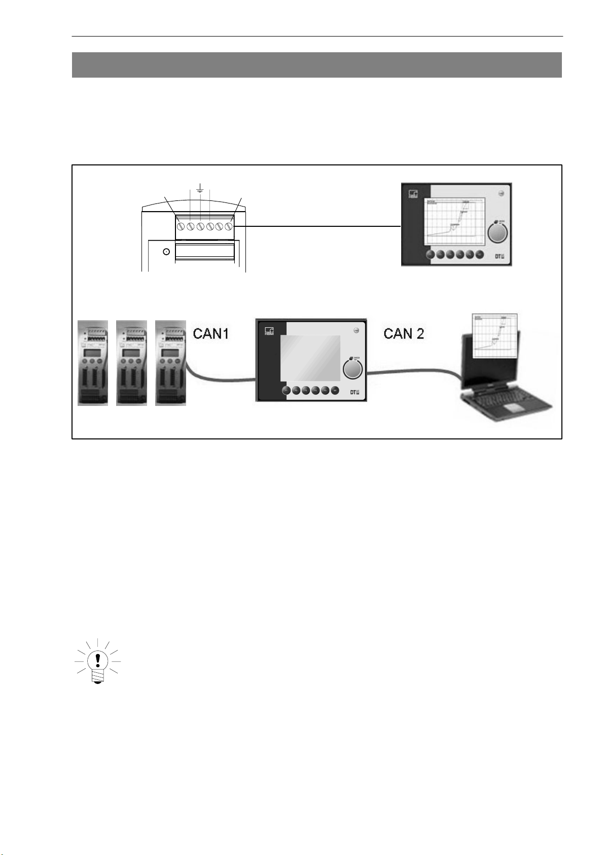
2 Application notes
The DT85 is an add-on for the twin-channel MP85 and MP85DP amplifiers of
the PME product family.
Most important applications of the DT85:
• Graphical representation of all measured values, evaluation windows and
press-fit curves with OK / NOK decision-making
• Displaying status information
• Viewing all the important MP85 settings
• Loading and storing parameter sets in/from flash or MMC memory
• Setting the most important parameters (e.g. tolerance windows) and
functions (sensor test)
• The DT85 is not suitable as a display for tolerance band mode, as an
evaluation criterion
NOTE
Measurement acquisition, analysis and curves/results storage
take place in the connected PME device. The DT85 serves as
a display and control unit.
HBM A1704-1.1 en
Page 9
DT85
9
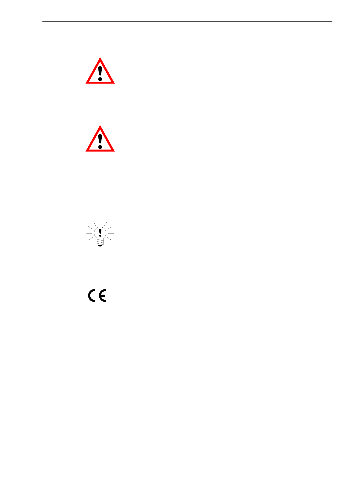
3 Connecting the DT85
Information is exchanged between the DT85 and the MP85(DP) modules via
the CAN bus.
Up to 10 MP85 modules can be connected and parameterized. The DT85 can
be supplied with voltage via the screw terminal of the MP85 module.
Low High
0V
+UB
X 2
Voltage supply and
CAN
CAN gateway
X 2
. . . . .max. 10
active
X 3
There are two possible applications:
• Connecting the DT85 display via the CAN bus on the MP85(DP) module
• Linking the PC with the DT85 via the second CAN interface (if necessary,
use a dongle at the PC, CAN-USB)
As soon as the PC is connected and the PME Assistant has been started up,
the display is muted and works as a gateway between the MP85 and the PC.
After closing the PME Assistant, the DT85 can be re-activated by the “DT85”
function.
NOTE
The DT85 can be both connected to the MP85(DP) module and
disconnected from the MP85(DP) module while measuring
mode is running, without detriment. This also applies to
connecting a PC to the PME Assistant.
HBMA1704-1.1 en
Page 10
10
3.1 Establish the measurement chain
PC with ”PME
Assistant” software
e.g. PLC
DT85
CAN
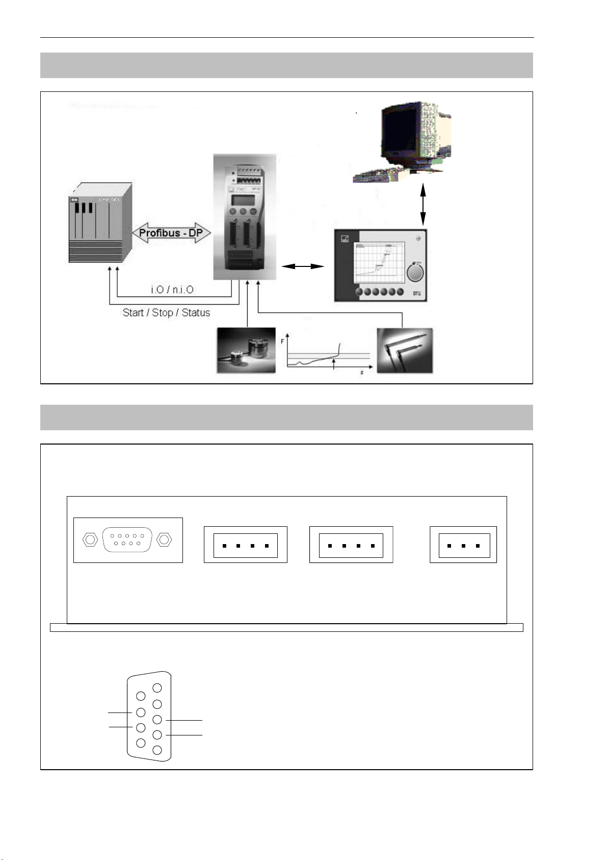
3.2 Pin assignment
Underneath the DT85 device
X4 X3 X2 X1
CAN
Sensors
CAN PC CAN MP85
External Display
DT85
RS232 programming
interface
1)
CAN
SCREEN
CAN GND
CAN L
CAN H
CAN
SCREE
N
CAN GND
CAN L
CAN H
+UB
GND
SCREEN
RS232 interface assignment 1):
GND
9
CTS
RTS
6
1)
Interface for service purposes: monitor, update, configuration
HBM A1704-1.1 en
5
TxD
RxD
1
Page 11
DT85
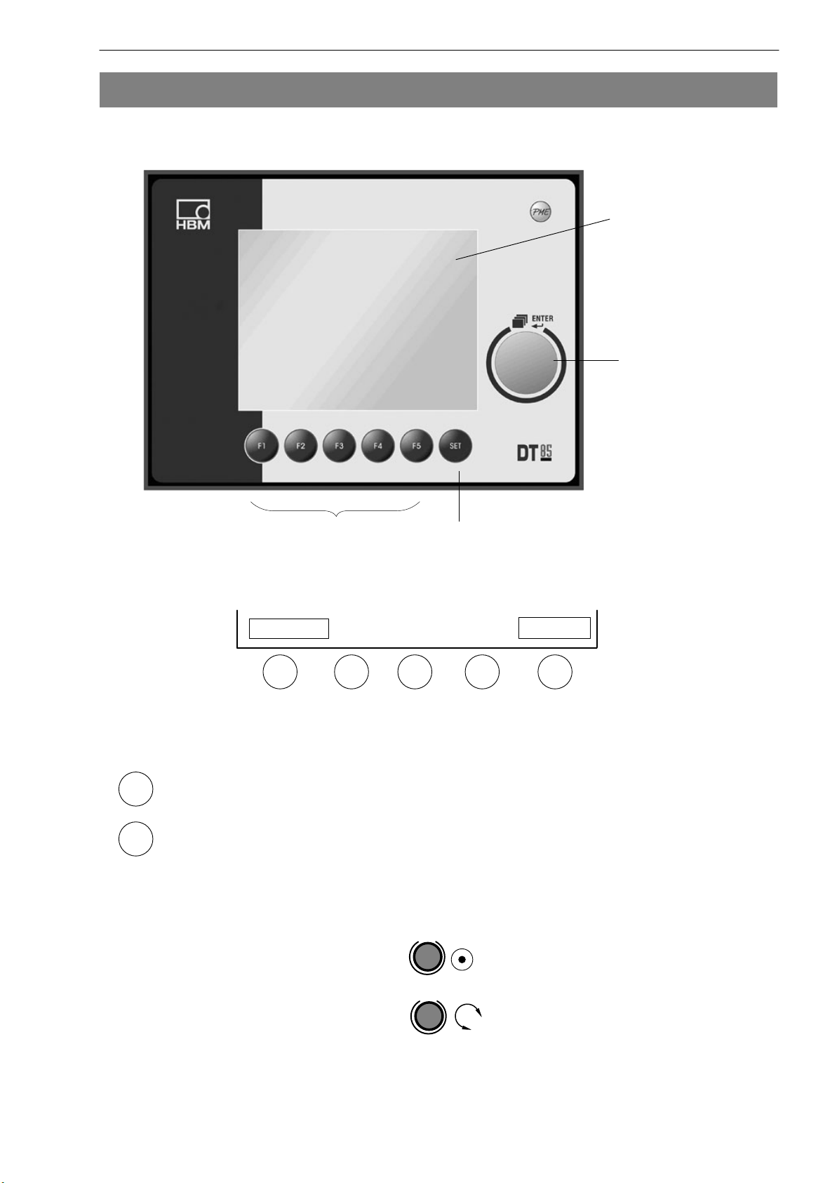
4 Setup and operation
Functions of the keys:
11
Display window
Rotary knob
with ENTER
key
F1 to F5 SET key
F1 to F5:
Example:
F1
- Key: Switching from setup level to display level
SET
- Key:
only assigned if shown in the display window
Measure
F1
In this example, keys F2 to F4 are not assigned.
Key F1 is assigned with MEASURE, key F5 with
PREVIOUS.
Switching from display level to setup level and navigating within setup
level
The following symbols are used below:
F2 F3 F4
Previous
F5
press:
rotate:
HBMA1704-1.1 en
Page 12

12
4.1 Set the baud rate
• Connect the DT85 to the MP85(DP) amplifier
• Switch on the devices
• Press keys F2 and F3 on the DT85 simultaneously
Display:
Main System
User Settings
CAN baud rate
Enter baud rate
Save and Exit
Exit
DT85
After exiting the system menu, the DT85 must be briefly disconnected from the
power supply (power-down-reset).
NOTE
The chosen baud rate must match the baud rate of the
connected PME device.
Factory setting 1 MBaud
HBM A1704-1.1 en
Page 13

DT85
4.2 Startup
Startup:
• Connect the DT85 to the MP85(DP) amplifier
• Switch on the devices
- DT85 performs a scan and displays all modules on the bus
Display (example):
NodeScan: 1 node found
113 MP85DP Ident. number of the detected device
.. (all the connected MP85(DP)s are shown)
13
• Rotate:
• Press ENTER:
Display:
- The DT85 is now in Display mode.
NOTE
Choose the required module
When several MP85(DP) modules are operated with one DT85, the SCAN
button can be used to display an overview of all devices on the bus and
switch the DT85 to another module.
HBMA1704-1.1 en
Page 14

14
4.3 Operating philosophy
Display level:
When it is switched on, the DT85 is in the display level.
Use to select the following display menus:
MEASURED VALUE DISPLAY – STATUS DISPLAY – GRAPHIC WINDOW LAST MEASUREMENT RESULT - STATISTICS
You cannot enter or set values at this level.
SET
Use to move to the main setup level menu from any window
Setup level:
Located under MAIN MENU. You can enter or set values here
(recognizable by text(figures) with a black background).
DT85
Example: MAINMEN
CHARACT. CURVE – ENTER CURVE – Zero pt.. electr. -0040.000
NOTE
Text marking at setup level:
Italics mean: read out only
non-italics: can be set with the ENTER key (see Page 21)
U - PREPARE MEASUREMENT - AMPLIFIER -
HBM A1704-1.1 en
Page 15

DT85
• Change setup values (black background):
Navigation with the ENTER key
15
- Select number
-
- Change last digit:
+0040.000
+0040.000
+0040.004
- Double-click
- Select previous digit:
- Double-click: Change digit
+0040.004
+0040.024
- Double-click: Change previous digit or use
- to exit change mode
Alternative way of changing setup values:
Navigation with keys F3 and F4
< - >
ƞ
Ɵ
(use F2 to change the sign)
- Select number
-F3
- Change digit:
+0040.000
(use F2 to change the sign)
+0040.004
- F3
- Select previous digit:
+0040.004
-F4
- Change digit
+0040.024
- F3 Select previous digit or use
- to exit change mode
Exit setup level:
Key F1 (MEASURE) will always take you to the last selected display mode.
HBMA1704-1.1 en
Page 16

16
4.4 Communication with the PME Assistant
NOTE
Gateway communication is also possible while measuring
mode is running.
• Connect the PC to the DT85 (connector X3)
X 2
X 3
DT85
• Start the PME Assistant
Display:
- The DT85 is bypassed, the MP85(DP) communicates directly with the
PME Assistant program
1)
• Back to the DT85 display:
Close the PME Assistant.
- Press key F1 on the DT85
1)
PME Assistant functionality is described in detail in its online Help.
HBM A1704-1.1 en
Page 17

DT85
4.5 ZOOM function
17
Use the ZOOM function to scale the graphic window (magnifying glass
function). In the factory setting, the display detail corresponds to the set range
window. The ZOOM range can be moved to any of the four pages.
Use the PREVIOUS key to transfer the set ZOOM range to the graphic
window, which also sets it up for all further measurements. The ZOOM Off key
resets the screen detail back to the size of the range window.
To zoom the window, you must first use the keys to select the required page,
for example, X1. You can then use the ENTER key (rotary knob) to modify the
view. Should further changes be necessary, you can now select and modify
the next page.
4.6 Passcode query
Factory setting 0000
Activate passcode:
0: disabled
1: active, that is to say, the passcode will be queried
If the passcode has been forgotten:
Code 1703 will always take you to the setup level.
See Page 21 for further details.
HBMA1704-1.1 en
Page 18

18
4.7 Overview of display readings
MAIN MENU (Setup level)
SYSTEM
MP85 default settings View only
DT85 default settings View only
PREPARE
MEASUREMENT
Amplifier
Transducer Display only
Characteristic curve Enter zero point and sensitivity
Signal preparation Run a zero balance
DT85
Passcode input, language change-
over
Transducer test Run a transducer test
Evaluation criteria Enter the range window
Enter the tolerance window
Enter the control settings
Data storage Specify storage medium and stor-
age parameters
Additional functions
Limit values 1-4 Modifiable numerical values
Digital inputs/outputs View only
SAVE AND LOAD
PARAMETERS
MEASUREMENT AND VISUALIZATION (Display level)
MEASURED VALUE
DISPLAY
STATUS DISPLAY Process status, status of Digital I/Os, alert notices
x/y channel with limit values, measurement status,
Saving and loading flash and MMC
equipment scan
GRAPHIC DISPLAY Measurement curve, tolerance window, graphic output
with units and zoom function, measurement results, rea-
son for ending measurement
LAST MEASUREMENT
RESULT
STATISTICS Displaying OK and NOK results per tolerance window,
HBM A1704-1.1 en
Measurement result with tolerance window output in
table form and window results of the last measurement
and process number, display of the entry and exit condi-
tions, status and evaluation method of each tolerance
window
can be switched for each parameter set with process
counter
Page 19

4.8 DT85 menu navigation
Display level
SET
key
MAIN MENU
Passcode query
(see Page 17)
SYSTEM
PREPARE MEASUREMENT
SAVE / LOAD PARAMETERS
Main menu
(setup level)
ENTER key
Measured value display Status display Graphic display Last measurement result Statistics
x/y measured values x/y measured values Parameter set Measurement result: Process counter
x/y measurement channel
status
Limit values Process status
Digital I/O status Process counter Process counter
MEASURE
Number of measurement
points
Display level
Reason for ending Window results
Display level
MEASURE key (F1)
Setup level
(each menu of the
main menu)
Parameter set (next parameter set: F1;
previous parameter set: F2)
Equipment scan / Equipment
selection
Alarm cause
Readings in the display
use
A1704-1.1 de DT85
SET
to move to setup level (MAIN MENU)
Measurement curve and eval-
uation window
Result Window name / Result
Process status
Reason for ending
Reason for alarm
Zoom (key F5)
UnZoom
Window results Window name / number / OK / NOK
Window entry and exit
conditions
Window status and evaluation
method
19
Page 20

20
A
Display level:
SET
Main menu
Measured value display
Status display
Graphic display
Last measurement result
Statistics
SYSTEM PREPARE MEASUREMENT SAVE/LOAD PARAMETERS
MP85 (DP) default
settings
DT85 default
settings
Setup level
Amplifier
Evaluation criteria
Transducer
Characteristic curve
Signal preparation
Transducer test
Alarm range window
Tolerance window
Control settings
Chart mapping
SET
SET
Loading flash
Saving in flash
Loading from MMC
DT85
Load parameters
from flash
SET
Save parameters
in flash
SET
Load parameters
from MMC
SET
Data storage
Additional
functions
1704-1.1 en
Results
Curves
Statistical data
LV1 + 2
LV 3 + 4
Dig. outputs
Dig. inputs
SET
SET
Saving to MMC
Save parameters
to MMC
SET
Page 21

SET
Main menu
SYSTEM
Setup level: SYSTEM
DEFAULT SETTINGS MP85
CAN + ID :
Device name :
Amplifier type :
Program version :
Hardware version :
Serial number :
Date/Time :
DT85
Note
italic: read out only
non-italic: adjustable with
and
A1704-1.1 de
MP85 (DP) default
settings
DT85 default
settings
Hardware synchronization: Master
MEASURE PREVIOUS
DEFAULT SETTINGS DT85
CAN baud rate :
Program version :
Specify passcode :
Activate passcode :
CHANGE OVER TO English language
Current language :
Program version :
MEASURE PREVIOUS
< - >
ƞ
Ɵ
NEXT
SYSTEM
SET
NEXT
SYSTEM
21
Page 22

Main menu
PREPARE MEASUREMENT
Setup level: PREPARE MEASUREMENT
22
DT85
Amplifier
Transducer
Characteristic
curve
Signal preparation
Transducer test
TRANSDUCER ID: 109
Channel x Channel y
Channel name Displacement Force
Transducer type Half bridge Full bridge
Measuring range
Decimal point
Unit
MEASURE
F5
Use to return to AMPLIFIER
PREVIOUS
NEXT
Transducer
Characteristic curve
Signal preparation
Transducer test
ENTER CURVE
ID 109
Zero pt. electr.
Zero pt. phys.
Sensitiv. electr.
Nom. val.. phys.
MEASURE
+ / -
Channel x Channel y
[mm ] [kN ]
< - >
ƞ
Ɵ
PREVIOUS
Transducer
Characteristic curve
Signal preparation
Transducer test
SIGNAL PREPARATION
ID 109
Channel x Channel y
[mm ] [kN ]
Zero balance START
Zero value
Zero reference
Low-pass filter.
NEXT NEXT
MEASURE PREVIOUS
START
TRANSDUCER TEST ID: 109
Channel x Channel y
[mm ] [kN ]
Setpoint
Deviation
Actual value=setpoint Yes
Yes
Transducer
Characteristic
curve
Signal preparation
Transducer test
A1704-1.1 en
Run test Start Start
Test ok?
MEASURE
PREVIOUS
NEXT
SET
TRANSDUCER
Page 23

Main menu
PREPARE MEASUREMENT
Setup level: PREPARE MEASUREMENT
DT85
Alarm and range windows
Evaluation criteria
Tolerance windows 1-3
Tolerance windows 4-6
Tolerance windows 7-9
Control setup
ENTER ALARM AND RANGE WINDOWS
ID: 109
Alarm window range window
Top right:
Channel X [mm] :
Channel Y [kN] :
Bottom left:
Channel X [mm] :
Channel Y [kN] :
MEASURE PREVIOUS
Use to return to
+ / -
F5
< - >
ƞ
Ɵ
EVALUATION CRITERIA
K
A1704-1.1 en
Alarm and range
windows
Tolerance windows 1-3
Tolerance windows 4-6
Tolerance windows 7-9
Control setup
NEXT
Alarm and range
windows
Tolerance windows 1-3
Tolerance windows 4-6
Tolerance windows 7-9
Control setup
TOLERANCE WINDOWS 1-3
Tol. wind: top/lft top/rt bot/lft bot/rt
#1 X[mm]:
#1 X[kN]:
#2X[mm]:
#2 X[kN]:
#3 X[mm]:
#3 X[kN]:
+ / -
PREVIOUS
CONTROL SETUP
ID: 109
Start condition: external
Start condition: external
Delta Channel X: mm
Delta Channel Y: kN
Max. meas. duration: s
MEASURE PREVIOUS
< - >
ƞ
Ɵ
NEXT
SET
Alarm and range
windows
Tolerance windows 1-3
Tolerance windows 4-6
Tolerance windows 7-9
Control setup
Alarm and range
windows
Tolerance windows 1-3
Tolerance windows 4-6
Tolerance windows 7-9
Control setup
TOLERANCE WINDOWS 4-6
Tol. wind: top/lft top/rt bot/lft bot/rt
#4 X[mm]:
#4 X[kN]:
#5X[mm]:
#5 X[kN]:
#6 X[mm]:
#6 X[kN]:
+ / -
PREVIOUS
TOLERANCE WINDOWS 7-9
Tol. wind: top/lft top/rt bot/lft bot/rt
#7 X[mm]:
#7 X[kN]:
#8X[mm]:
#8 X[kN]:
#9 X[mm]:
#9 X[kN]:
+ / -
ALARM AND RANGE WINDOWS
PREVIOUS
to K
23
Page 24

Main menu
PREPARE MEASUREMENT
Setup level: PREPARE MEASUREMENT
24
DT85
Data storage
F5
Use to return to
PREPARE MEASUREMENT
DATA STORAGE ID: 109
Target memory on MMC MMC:
on MMC via CAN
Storage method without loss of data
without loss of data Optimized to process
Save results: all
none all NOK only OK only
Save curves : all
none all NOK only OK only
Save statistical data: Save
MEASURE PREVIOUS
NEXT
SET
ADDITIONAL FUNCTIONS
A1704-1.1 en
Page 25

Main menu
PREPARE MEASUREMENT
Setup level: PREPARE MEASUREMENT
DT85
Additional
functions
Limit values 1+2
Limit values 3+4
Digital outputs
Digital inputs
LIMIT VALUE 1+2 ID: 109
Limit value 1: Channel x Channel y
Monitoring: On Off
Switching direction Overshoot Overshoot
Level:
Hysteresis:
Limit value 2: Channel x Channel y
Monitoring: Off Off
Switching direction Overshoot Overshoot
Level:
Hysteresis:
< - >
MEASURE PREVIOUS
Use to return to
+ / -
F5
ƞ
Ɵ
ADDITIONAL FUNCTIONS
A1704-1.1 en
Limit values 1+2
Limit values 3+4
Digital outputs
Digital inputs
LIMIT VALUE 3+4 ID: 109
Limit value 3: Channel x Channel y
Monitoring: Off Off
Switching direction Undershoot Undershoot
Level:
Hysteresis:
Limit value 4: Channel x Channel y
Monitoring: Off Off
Switching direction Undershoot Undershoot
Level:
Hysteresis:
< - >
NEXT NEXT
MEASURE PREVIOUS
+ / -
ƞ
Ɵ
DIGITAL INPUTS
Input Channel X Channel Y
Zero balance
Shunt calibr.
Load par. Bit 0
Load par. Bit 1
Load par. Bit 2
Load par. Bit 3
Load par. Bit 4
Start/Stop
Transducer test
Clear stats
Save stats
MEASURE PREVIOUS
NEXT
SET
Limit values 1+2
Limit values 3+4
Digital outputs
Digital inputs
Limit values 1+2
Limit values 3+4
Digital outputs
Digital inputs
DIGITAL OUTPUTS
Output Function Level
Output 1: LV 1x positive
Output 2:
Output 3:
Output 4:
Output 5:
Output 6:
Output 7:
Output 8:
MEASURE PREVIOUS
LIMIT VALUE 1+2
NEXT
25
Page 26

Main menu
SAVE/LOAD
PARAMETERS
Setup level: SAVE / LOAD PARAMETERS
26
DT85
SAVE AND
LOAD
PARAMETERS
Loading from flash
Saving in flash
Loading from MMC
Saving to MMC
LOAD PARAMETERS FROM FLASH
ID: 109
Load parameter set : 01
0 Factory setting
MEASURE PREVIOUSLOAD CANCEL
Loading from flash
Saving in flash
Loading from MMC
Saving to MMC
SAVE PARAMETERS IN FLASH
ID: 109
Save parameter set : 01
NEXT NEXT NEXT
MEASURE PREVIOUSSAVE CANCEL
Loading from flash
Saving in flash
Loading from MMC
Saving to MMC
Loading from flash
Saving in flash
Loading from MMC
Saving to MMC
LOAD PARAMETERS FROM MMC
ID: 109
Load parameter set : 01
MEASURE PREVIOUSLOAD CANCEL
SAVE PARAMETERS TO MMC
ID: 109
F5
Use to return to SAVE
AND LOAD PARAMETERS
A1704-1.1 en
Save parameter set : 01
MEASURE PREVIOUSSAVE CANCEL
NEXT
SET
LOAD PARAMETERS FROM FLASH
Page 27

DT85
5 Typical measurement mode displays
27
Device name of the selected PME
Device number of the selected PME
- Measurement channels displayed
as a numerical value with error
status. Error message output as
”plain text”.
- The other PME modules are
displayed and selected via the
Scan function.
- Status display of the digital
inputs/outputs (1=active / 0 =
inactive).
- Status display of the entire process
and of the possible alarm cause.
HBMA1704-1.1 en
Page 28

28
corresponds to the range window and can be modified with the ZOOM function
- Graphical representation of the
entire process with results display
and status messages.
- In a case of NOK, the screen is
switched to inverse, to make the
NOK processes easier to recognize.
- The upper X axis is used to display
the coordinates for relative
(dynamic) windows.
See Section 4.5 for a description of the
ZOOM function
DT85
- Detailed result display for each
tolerance window and of the overall
result.
This allows conclusions to be drawn
about the course and the status of
the production process.
- Exact statistics for each tolerance
window.
Statistics can be called up for each
parameter set (Use PS+ and PS- to
select the next or the previous
parameter set). PS = parameter set
HBM A1704-1.1 en
Page 29

DT85
6 Explanations for the fundamental display parameters
Display Parameters Meaning
29
MEASURED
VALUE DIS-
PLAY
Display Parameters Meaning
STATUS
DISPLAY
Display Parameters Meaning
GRAPHIC
DISPLAY
x/y measured
values
Limit values
SCAN Equipment scan looks for connected MP85 modules
Digital I/O status Switching status of the digital I/Os
Process status Status of the measurement process
Alarm cause Alarm window message
PS: Parameter
set
PN: Process
counter
MP: Number of
measurement
points
Measured value display for channels x and y with the
measurement status in plain text
Limit values 1-4; F = active, f = inactive
1: ON; 0: OFF
Active parameter set in the selected MP85 module
Current process number
Number of measurement curve measurement points
Measurement
curve and evalu-
ation window
Result Overall measurement result (OK / NOK)
Process status Status of the measurement process
End Reason for ending measurement
Alarm cause Alarm window message
Zoom Setting scaling for the x and y axes (detail function)
Course of the curve display with a set tolerance window
and an alarm and range window;
As a default, the display range is set to the size of the
range window; use the ZOOM function to modify the
display range.
HBMA1704-1.1 en
Page 30

30
Display Parameters Meaning
DT85
LAST MEASUREMENT
RESULT
Measurement
Overall measurement result (OK / NOK)
result:
Process number Current process number
Reason for end-
Reason for ending measurement
ing
Window 1... 9 Plain text display of the tolerance window with window
name and curve evaluation in this tolerance window
Display Parameters Meaning
STATISTICS Process number Current process number
Parameter set Selected parameter set for the statistics display; select
with ”PS+ and ”PS-”.
Number of pro-
cesses
Total number of processes on which the statistics dis-
play is based; since the last time the statistics were
cleared.
Windows 1...9 Plain text display of the tolerance window with the win-
dow name and the number of OK and NOK processes.
Window parame-
ters
En
Ex
St
Ev
En = entry ( from the left, from the right)
Ex = exit ( from below, from above)
St = window status (A = activ / I = inactiv)
Ev = evaluation method (A = absolute, R = relative,
AV = mean value, Rt = real-time window)
HBM A1704-1.1 en
Page 31

DT85
7 Explanation of the main setup parameters
SYSTEM Parameters Meaning
31
MP85 (DP)
default set-
tings
DT85 default
settings
PREPARE
MEA-
SUREMENT
Device ID
Device name
Hardware and
firmware ver-
sions
Serial number
Program
version
Passcode speci-
fication
Language
changeover
Parameters Meaning
Specifying and activating the 4-digit passcode (1=ac-
When the passcode is active, the setup level pages are
disabled; should the passcode have been forgotten,
use the master passcode 1703 to enable them.
Changing the language used by the DT85 and the
MP85(DP) settings
Display ONLY
DT85 program version display
tive / 0=inactive);
MP85(DP)
Amplifier Transducer Display of selected transducers for both measurement
channels
Characteristic
curve
Signal
preparation
Transducer test Running a transducer test for both measurement
Evaluation
criteria
Data storage Target memory Choice of storage medium; display of available
Alarm range
window
Tolerance
window
Control settings Display of the start and stop conditions for
Adjustment of the transducer characteristic for both
measurement channels
Running a zero balance for both measurement
channels
Display of zero value and the set low-pass filter
channels
Display of the range and alarm window coordinates;
the range window can be modified
Display and adaptation of the coordinates of tolerance
windows 1 to 9
measurement;
Displaying and setting the increment for the measure-
ment points of the curve and the max. sampling time
memory when MMC card inserted
Results curves Choice of results and curves that are to be stored
HBMA1704-1.1 en
Page 32

32
DT85
Statistical data Save statistical data in the MP85(DP)
Additional
functions
SAVE/LOAD
PARAME-
TERS
LV1 + 2
LV3 +4
Digital outputs Display of the set digital output functions of the
Digital inputs Display of the set digital input functions of the
Parameters Meaning
Loading flash Loading a parameter set (full device setup) of the
MP85(DP) from flash memory in the RAM of the
The process only starts once the ”Load” key is
Saving flash Saving a parameter set (full device setup) of the
MP85(DP) from the RAM to the flash memory of the
The process only starts once the ”Save” key is
Display of limit value settings,
level and hysteresis can be adjusted
MP85(DP)
MP85(DP)
MP85(DP);
(00 = factory setting).
pressed.
MP85(DP);
pressed.
Loading MMC Loading a parameter set (full device setup) of the
MP85(DP) from the MMC card in the RAM of the
MP85(DP).
The process only starts once the ”Load” key is
pressed.
Saving to MMC Saving a parameter set (full device setup) of the
MP85(DP) from the RAM to the MMC card.
The process only starts once the ”Save” key is
pressed.
HBM A1704-1.1 en
Page 33

DT85
33
8 Error messages
The messages displayed as status messages on the DT85 result from the
MP85. Therefore, MP85 settings have to be changed accordingly or the errors
must be corrected.
Error message Cause Remedy
TransdErr. Input signal overflow
Transducer not connected
Transducer wrongly connected
Amplifier not adapted to transducer
type
No sensor circuits connected
ADC ovfl. Input signal of the A/D converter too
high
Grs ovfl. Gross value overflow Reduce display by one decimal
Scal.Err Input characteristic too steep Modify input characteristic
Connect transducer
See pin assignment
Connect sensor circuits
Adjust hardware measuring
range
place
Flash error An error occurred when reading out
the Flash EOROM.
This can be a one-off read error,
please repeat the operation. If
the error occurs again, please
contact HBM Service.
For more details, please refer to the MP85 online help and operating manual.
If CAN bus communication between DT85 and MP85 does not work
properly, the below message is displayed:
The MP85 still remains operative and will not be affected.
If the interruption has been only temporary, press the ENTER key
or F1
for acknowledgement. Otherwise, the wiring has to be checked or the devices
must be restarted.
HBMA1704-1.1 en
Page 34

34
DT85
9 Specifications (VDI/VDE2638)
DT85
Display Backlit LCD-Display, monochrome background
illumination with auto contrast function
Resolution Pixels 320 x 240 (1/4 VGA)
Active display area mm 120 x 90
Faceplate Plexiglas
Operation 6 function keys with tactile touch
Password Certain levels can be assigned password protection
Dialog Can be changed to German or English
Supply voltage V
Power consumption W 5
Electrical connections 2 x CAN bus (elec. isolated), COMBICON connector,
Nominal (rated) temperature
range
Storage (rated) temperature
range
Relative humidity % 20 ... 80 (non-condensing)
Shock (11 ms), max. G 5
Vibration (5-65 Hz), max. G 0,5
Dimensions mm 216 x 158 x 45 (W x H x D)
Mounting 6 x M3 fastening bolts
Cutout in panel frame mm 185 x 130 (W x H)
Degree of protection IP52 at the front
Weight g 800
C
C
DC
1 x power supply / COMBICON connector, 3-pin
1 x RS232 for service
o
o
18 ... 30
4-pin
0 ... +50
-20 ... +70
HBM A1704-1.1 en
Page 35

DT85
35
HBMA1704-1.1 en
Page 36

pp
A1704-1.1 en
Modifications reserved.
All details describe our products in general form only. They are
not to be understood as express warranty and do not constitute
any liability whatsoever. and constitute no form of liability.
Hottinger Baldwin Messtechnik GmbH
Postfach 10 01 51, D-64201 Darmstadt, Germany
Im Tiefen See 45, D-64293 Darmstadt, Germany
Tel.: 061 51/ 8 03-0; Fax: 061 51/ 8039100
E-mail: su
ort@hbm.com www.hbm.com
 Loading...