

HBM DIS2116 Quick Start Manual
Quick Start Guide
Kurzanleitung
Scale electronics
Waagenelektronik
DIS2116
A2540-1.1 en/de

2
DIS2116
Contents Page
Typographical conventions 5 . . . . . . . . . . . . . . . . . . . . . . . . . . . . . . . . . . . . .
Important information 5 . . . . . . . . . . . . . . . . . . . . . . . . . . . . . . . . . . . . . . . . . .
Safety instructions 6 . . . . . . . . . . . . . . . . . . . . . . . . . . . . . . . . . . . . . . . . . . . . .
1 Introduction and appropriate use 7 . . . . . . . . . . . . . . . . . . . . . . . . . . . . .
2 Special features 7 . . . . . . . . . . . . . . . . . . . . . . . . . . . . . . . . . . . . . . . . . . . . .
3 Mechanical construction and scope of supply 8 . . . . . . . . . . . . . . . . .
3.1 Scope of supply 8 . . . . . . . . . . . . . . . . . . . . . . . . . . . . . . . . . . . . . . . .
3.2 Accessories, to be ordered separately 9 . . . . . . . . . . . . . . . . . . . . .
4 Scale commissioning overview 9 . . . . . . . . . . . . . . . . . . . . . . . . . . . . . . .
4.1 Initial commissioning 10 . . . . . . . . . . . . . . . . . . . . . . . . . . . . . . . . . . .
4.2 NAWI application 10 . . . . . . . . . . . . . . . . . . . . . . . . . . . . . . . . . . . . . .
4.3 NAWI application (vehicle scale) 11 . . . . . . . . . . . . . . . . . . . . . . . . .
5 Electrical connections 12 . . . . . . . . . . . . . . . . . . . . . . . . . . . . . . . . . . . . . .
5.1 Notes 12 . . . . . . . . . . . . . . . . . . . . . . . . . . . . . . . . . . . . . . . . . . . . . . . .
5.2 Cable connection 12 . . . . . . . . . . . . . . . . . . . . . . . . . . . . . . . . . . . . . .
5.3 Cable preparation 12 . . . . . . . . . . . . . . . . . . . . . . . . . . . . . . . . . . . . . .
5.3.1 Connecting DIS2116 with C16i 13 . . . . . . . . . . . . . . . . . . . . . .
5.3.2 Connecting VKD2R-8 with DIS2116 and C16i 14 . . . . . . . . .
5.4 Load cell connection 15 . . . . . . . . . . . . . . . . . . . . . . . . . . . . . . . . . . .
5.5 Supply voltage 15 . . . . . . . . . . . . . . . . . . . . . . . . . . . . . . . . . . . . . . . .
5.6 Voltage outputs 15 . . . . . . . . . . . . . . . . . . . . . . . . . . . . . . . . . . . . . . . .
5.7 RS485 interface (Terminal block K1) 16 . . . . . . . . . . . . . . . . . . . . . .
5.8 Terminal block K1 assignments 16 . . . . . . . . . . . . . . . . . . . . . . . . . .
5.9 RS232 interface (COM2) 17 . . . . . . . . . . . . . . . . . . . . . . . . . . . . . . . .
5.10 RS232 interface (COM3) 18 . . . . . . . . . . . . . . . . . . . . . . . . . . . . . . . .
5.11 RS-232 interface (COM4) 18 . . . . . . . . . . . . . . . . . . . . . . . . . . . . . . .
5.12 PS2 keyboard interface 18 . . . . . . . . . . . . . . . . . . . . . . . . . . . . . . . . .
5.13 USB printer interface 18 . . . . . . . . . . . . . . . . . . . . . . . . . . . . . . . . . . .
5.14 Interface-Schnittstelle (COM5) 18 . . . . . . . . . . . . . . . . . . . . . . . . . . .
6 Control and display functions 19 . . . . . . . . . . . . . . . . . . . . . . . . . . . . . . .
6.1 Device view 19 . . . . . . . . . . . . . . . . . . . . . . . . . . . . . . . . . . . . . . . . . . .
6.2 Operator controls 20 . . . . . . . . . . . . . . . . . . . . . . . . . . . . . . . . . . . . . .
6.3 Display 20 . . . . . . . . . . . . . . . . . . . . . . . . . . . . . . . . . . . . . . . . . . . . . . .
HBM A2540-1.1 en/de

DIS2116
7 Basic scale functions 22 . . . . . . . . . . . . . . . . . . . . . . . . . . . . . . . . . . . . . . .
7.1 Zero setting the scale 22 . . . . . . . . . . . . . . . . . . . . . . . . . . . . . . . . . .
7.2 Switching on and off 23 . . . . . . . . . . . . . . . . . . . . . . . . . . . . . . . . . . . .
7.3 Gross/net selection 24 . . . . . . . . . . . . . . . . . . . . . . . . . . . . . . . . . . . .
7.4 10-fold resolution 24 . . . . . . . . . . . . . . . . . . . . . . . . . . . . . . . . . . . . . .
7.5 Taring 24 . . . . . . . . . . . . . . . . . . . . . . . . . . . . . . . . . . . . . . . . . . . . . . . .
7.6 Manual tare function 25 . . . . . . . . . . . . . . . . . . . . . . . . . . . . . . . . . . .
7.7 Zero on start-up 25 . . . . . . . . . . . . . . . . . . . . . . . . . . . . . . . . . . . . . . .
7.8 Error displays 26 . . . . . . . . . . . . . . . . . . . . . . . . . . . . . . . . . . . . . . . . .
7.9 Standstill recognition 26 . . . . . . . . . . . . . . . . . . . . . . . . . . . . . . . . . . .
8 Vehicle scale 27 . . . . . . . . . . . . . . . . . . . . . . . . . . . . . . . . . . . . . . . . . . . . . . .
8.1 Activate “VEHICLE SCALE” operating mode 27 . . . . . . . . . . . . . . .
8.2 Edit database 27 . . . . . . . . . . . . . . . . . . . . . . . . . . . . . . . . . . . . . . . . .
8.2.1 Editing vehicle data 28 . . . . . . . . . . . . . . . . . . . . . . . . . . . . . . .
3
8.2.2 x Delete vehicle 29 . . . . . . . . . . . . . . . . . . . . . . . . . . . . . . . . . .
8.2.3 V Create vehicle 29 . . . . . . . . . . . . . . . . . . . . . . . . . . . . . . . . .
8.3 Vehicle weighing mode Check-in/Check-out 29 . . . . . . . . . . . . . . .
9 Alibi and calibration memory 32 . . . . . . . . . . . . . . . . . . . . . . . . . . . . . . . .
9.1 Reading the stored files 32 . . . . . . . . . . . . . . . . . . . . . . . . . . . . . . . . .
10Graphic display 33 . . . . . . . . . . . . . . . . . . . . . . . . . . . . . . . . . . . . . . . . . . . . .
10.1 Oscilloscope 33 . . . . . . . . . . . . . . . . . . . . . . . . . . . . . . . . . . . . . . . . . .
10.2 Center of gravity 34 . . . . . . . . . . . . . . . . . . . . . . . . . . . . . . . . . . . . . . .
11Parameter factory settings 36 . . . . . . . . . . . . . . . . . . . . . . . . . . . . . . . . . .
12Monitoring functions and error messages 37 . . . . . . . . . . . . . . . . . . . .
12.1 Monitoring functions 37 . . . . . . . . . . . . . . . . . . . . . . . . . . . . . . . . . . . .
12.2 Error messages 37 . . . . . . . . . . . . . . . . . . . . . . . . . . . . . . . . . . . . . . .
13Specifications 41 . . . . . . . . . . . . . . . . . . . . . . . . . . . . . . . . . . . . . . . . . . . . . .
Specifications (Continuation) 42 . . . . . . . . . . . . . . . . . . . . . . . . . . . . . . . .
14Dimensions (in mm; 1 mm = 0.03937 inches) 44 . . . . . . . . . . . . . . . . . .
14.1 DIS2116 and cutout in the panel-frame 44 . . . . . . . . . . . . . . . . . . .
14.2 Desktop housing, also for wall mounting 44 . . . . . . . . . . . . . . . . . .
15Operator dialog and setup parameters 45 . . . . . . . . . . . . . . . . . . . . . . .
HBMA2540-1.1 en/de
4
DIS2116
Typographical conventions
For clear identification and improved legibility, the following conventions have
been used in this documentation:
NOTE
Important paragraphs are marked with a symbol to draw attention to
them.
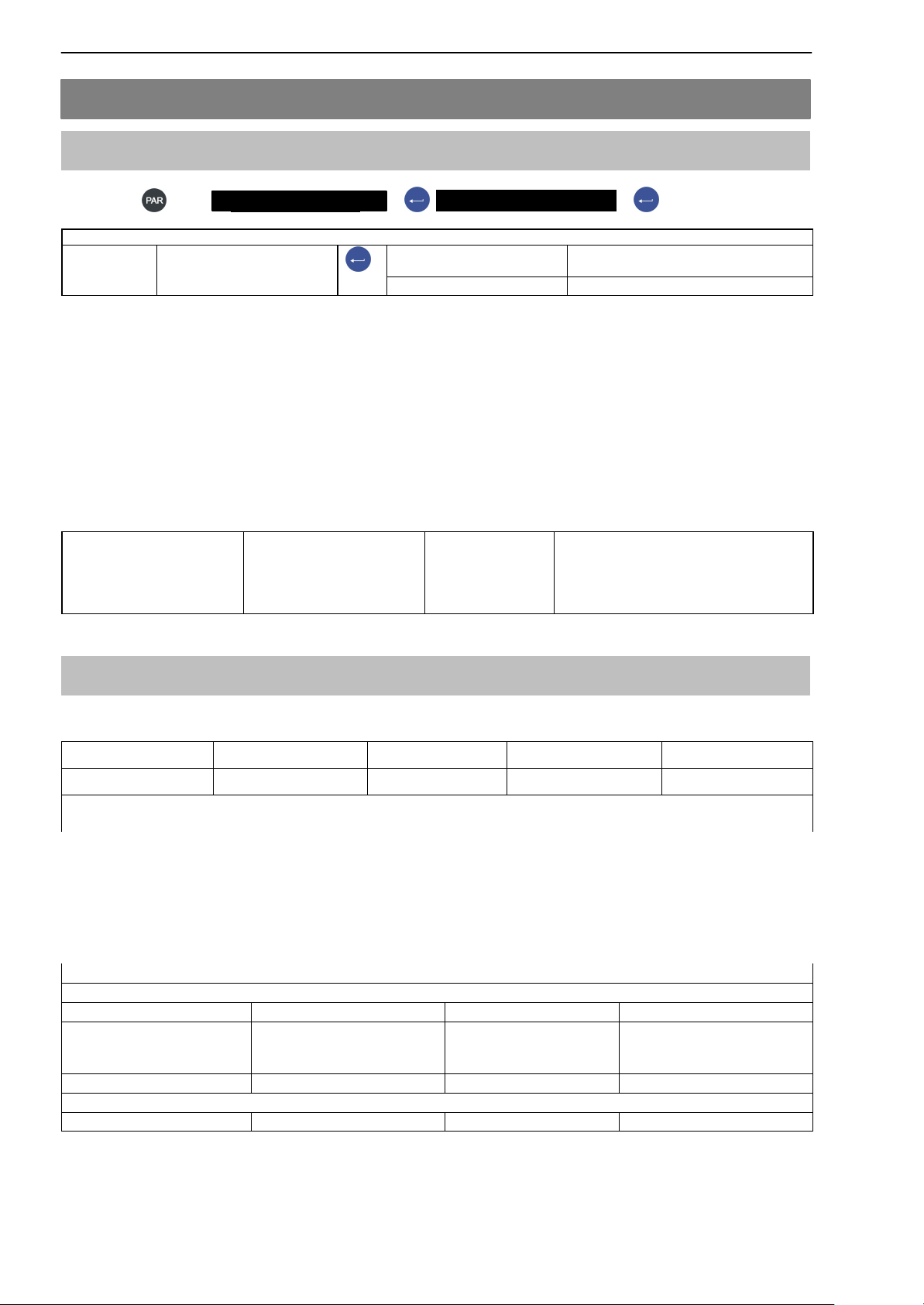
Italics Indicates external documents and files
“MODE” All menus and menu commands appear in quotes, here the
main menu “MODE”.
“ENTER” Quotes and italics are used for keys, input fields and user
input.
TAR Bold is used for communication commands.
Er1250
Underlined normal print is used for error messages.
Important information
NOTE
Neither the design of the device nor any technical safety aspects may be modified without the express permission of Hottinger Baldwin Messtechnik
GmbH. Any modification excludes Hottinger Baldwin Messtechnik GmbH from
any and all liability for any damage resulting therefrom.
When replacing the battery for the real-time clock, the device must be disconnected from the power supply (service life y 5 years).
It is strictly forbidden to carry out any repairs and soldering work on the motherboards or to replace any components. Repairs may only be carried out by
persons authorized by Hottinger Baldwin Messtechnik GmbH.
The production number set at the factory cannot be changed.
When connecting the cables, the device must be disconnected from the vol-
tage supply.
HBM A2540-1.1 en/de

DIS2116
Safety instructions
• There are not normally any hazards associated with the product, provided
the notes and instructions for project planning, installation, appropriate operation and maintenance are observed.
• It is essential to comply with the safety and accident prevention regulations
specific to the particular application.
• Installation and start-up must only be carried out by suitably qualified personnel.
• Do not allow damp and dirt to get inside the device when connecting the
cables.
• When connecting the cables, take action to prevent electrostatic discharge
as this may damage the electronics.
• The required power supply for the device is an extra-low voltage (10...30 V)
with safe disconnection from the mains.
5
• When connecting additional devices, comply with the safety requirements.
• The ground connections of the supply voltage, the interface and the load
cell cable shield are interconnected in the device. If the potentials of the devices to be connected are different, suitable steps must be taken to isolate
the signals (such as using an optocoupler).
• Shielded cables must be used for all connections apart from the supply voltage (see note below). The shield must be connected to the provided terminals (Chapter 5.3, page 11).
• The use of unshielded cables for the voltage supply is only permissible for
cables with a maximum length of 30 m, laid inside buildings. If cables are
longer or are installed outside buildings, shielded cables must be used (as
per EN 61326−1).
• To compensate for potential differences, the metal housing of the DIS2116
must be connected to the scale structures as well as to the ground potential of the connected devices by a low-resistance equalizing conductor. This
is unnecessary if a potential difference of 35 V is not exceeded.
• In the device, the reference ground (GND) of all the signals and the supply
voltage is connected directly to the cable shield connection but not to the
housing.
• Connection to a wide-ranging supply network is not permitted as this often
causes interfering voltage peaks to be coupled into the electronics. Instead,
a local supply must be provided for the DIS2116 (even when grouped).
• The front foil is made from high-quality materials, providing a service life
appropriate to the external conditions. The keys must only be operated by
hand; under no circumstances must pointed objects be used to press them.
HBMA2540-1.1 en/de

6
DIS2116
1 Introduction and appropriate use
This Operating Manual contains detailed information both on operation and on
the setting options of the DIS2116 weighing electronics.
The DIS2116 is designed for use in industrial applications, for example
• as a legal-for-trade main display for up to 24 digital load cells (e.g. C16i) as
components of a non-automatic scale (NAWI)
• as a vehicle scale with max. 3 segments as a compound weighing machine
Use for any purpose other than the above is deemed to be inappropriate.
In the case of legal-for-trade use, national legal and safety regulations must
be complied with.
1)
NAWI – non automatic weighing instrument
1)
2 Special features
The DIS2116 is a digital display unit for connection to digital load cells.
The DIS2116 has available:
D RS485 4-wire connection for up to 24 digital load cells
D Menu for a vehicle scale with up to 3 segments and max. 8 load cells per
segment
D Encrypted transmission of measured values between DIS2116 and load
cells in legal-for-trade mode
D COM port for serial communication with a PC / PLC (RS232)
D COM port for a printer (RS232 or USB)
D COM port for external large-scale display (RS232)
D COM port for connection to fieldbuses
D PS2 connection for external keyboard
D Internal SD card as alibi memory for print data and settings
D Real-time clock with battery buffering
D Supply voltage range 10...30 V
DC
D Voltage output for supply of digital load cells
The electronics are set and parameterized via keyboard or interface.
HBM A2540-1.1 en/de
DIS2116
Additional features:
D Use as 1, 2 or 3-range scale
D Disabling/enabling of menu functions
D Filter selection
D Max. capacity adjustment, partial load adjustment
D Zero on start-up
D Automatic zero tracking
D Weighing range linearization
D Different print functions
D Numerous monitoring and error detection functions
3 Mechanical construction and scope of supply
7
3.1 Scope of supply
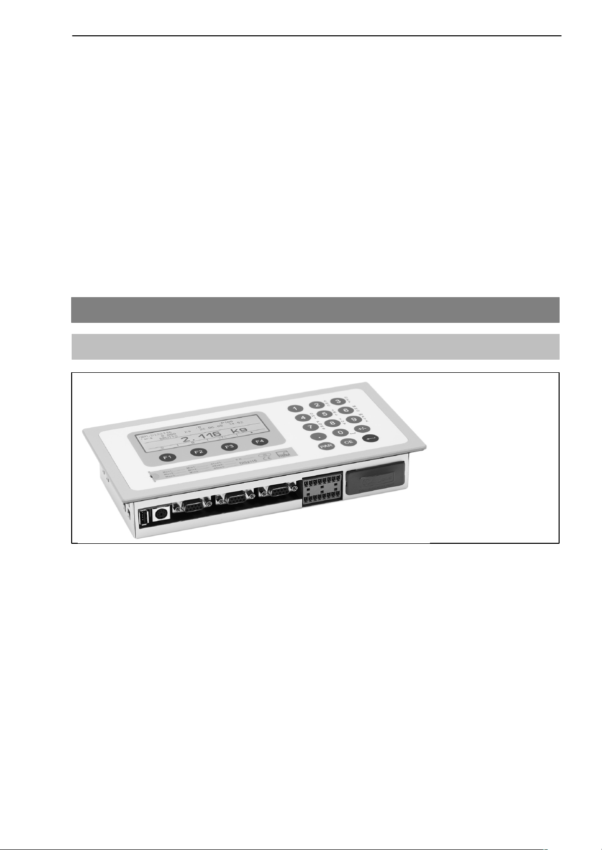
Fig. 3.1: DIS2116 view
• DIS2116 scale electronics in aluminum housing for panel mounting
• Adhesive label for closing and sealing the opening for the calibration push-
button and labeling strips
• 8 labeling strips for creating the scale type plate
• Two 8-pin mating connectors (Phoenix Mini-Combicon mating connector
8 pin Type: MC1.5/8-ST-3.81)
• Two connector housing with strain relief (Phoenix Mini-Combicon connector
housing 8 pin Type: KGG-MC 1.5/9)
HBMA2540-1.1 en/de
8
DIS2116
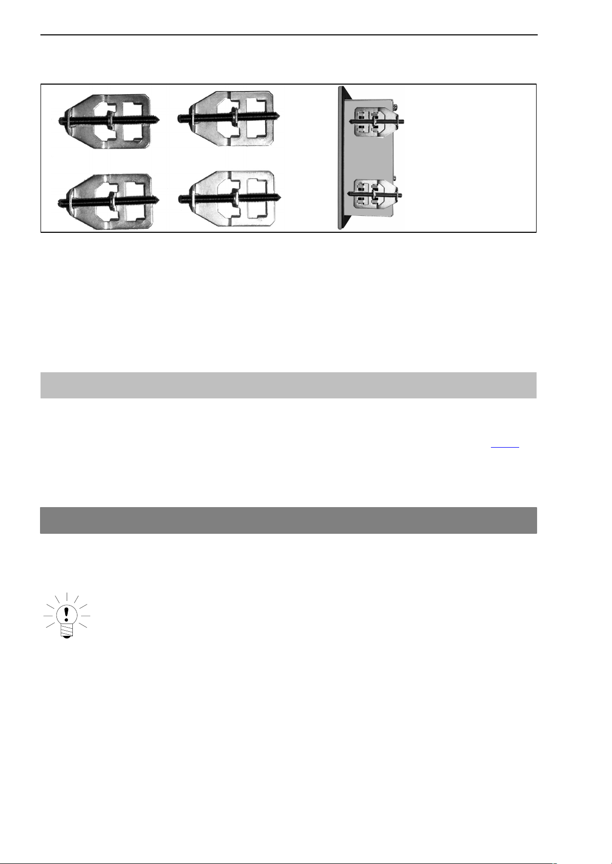
• 4 mounting elements for panel mounting
For DIS2116 panel mounting, the cut guides are bent outward for fitting the
mounting elements. Then, the set screws are used for clamping the housing
to the panel.
• SD card (1 Gbyte) installed in DIS2116
• Quick start guide
• System CD, 1-DIS2116-DOC
3.2 Accessories, to be ordered separately
• Power pack, AC/DC 15 V / 530mA (for max. 8 load cells)
• Desktop housing, also for wall mounting, 1-TG2116 (for Dim. see Chap. 14.2
• Junction box VKD2R-8
• Cable (connection cable for C16i)
4 Scale commissioning overview
The permissible supply voltage for the DIS2116 is in the range of +10...30 V
and must be adequately smoothed (rms value less residual ripple >10 V).
)
DC
NOTE
When the digital load cells, e.g. C16i are supplied via the DIS2116, the permissible supply voltage is +10 ... 17 V
DC
A 100...240 V power supply unit is available as an accessory (AC/DC15 V / 530
mA, for max. 8 load cells). This power pack is suitable for all digital load cells.
When properly connected with shielded cables, the DIS2116 complies with the
relevant European standards and carries the CE mark.
A formatted SD card with the parameters of the factory setting is inserted in
the device.
HBM A2540-1.1 en/de

DIS2116
Mechanical dimensions are described in chapter 14 (page 43 ) and mounting
information in chapter 3, page 7 .
Subsequent sub-chapters provide an overview of the sequence of steps that
need to be taken to commission the scale, depending on the application:
• Initial commissioning
1)
• As a component of a non-automatic scale (NAWI)
³ Chapter 4.1 (page 9)
• As a component of a vehicle scale ³ Chapter 4.3 (page 10)
This overview includes information on the respective chapters in this Operating Manual.
1)
NAWI – non automatic weighing instrument
4.1 Initial commissioning
• Mounting the device, Chapter 3 (page 7)
9
• Connecting the digital load cell(s), Chapter 5 (page 11) and 5.4 (page 14)
• Connecting the supply voltage, Chapter 5 (page 11) and 5.5 (page 14)
• Connecting the serial connections, Chapter 5 (page 11), 5.8 (page 15) or
5.9 (page 16)
• Switching on the device, Chapter 7.2 (page 22)
• Configuration of the load cells, Chapter 10.1 (page 32)
4.2 NAWI application
• Mounting the device, Chapter 3 (page 7)
• Connecting the digital load cell(s), Chapter 5 (page 11) and 5.4 (page 14)
• Connecting the supply voltage, Chapter 5 (page 11) and 5.5 (page 14)
• Connecting the serial connections, Chapter 5 (page 11), 5.8 (page 15) or
5.9 (page 16)
• Switching on the device, Chapter 7.2 (page 22)
the following steps are described on the system CD
• Calling the parameter menu via the hidden key
• Enabling all menu functions
• Configuration of the load cells
• Setting the weighing range
• Setting the correct filters
• Adjusting the weighing range
• Digital off-center load compensation (if necessary)
HBMA2540-1.1 en/de

10
• Linearization (only when necessary)
• Settings for legal-for-trade applications
• Parameter settings for serial interfaces
• Setting the date and time
• Disabling menu functions (if necessary)
• Filling out the labeling strip, securing the labeling strip
• Checking settings and functions
DIS2116
4.3 NAWI application (vehicle scale)
• Mounting the device, Chapter 3 (page 7)
• Connecting the load cell(s), Chapter 5 (page 11) and 5.4 (page 14)
• Connecting the supply voltage, Chapter 5 (page 11) and 5.5 (page 14)
• Connecting the serial connections, Chapter 5 (page 11), 5.8 (page 15) or
5.9 (page 16)
• Switching on the device, Chapter 7.2 (page 22)
the following steps are described on the system CD
• Calling the parameter menu via the hidden key
• Enabling all menu functions
• Configuration of the load cells
• Setting the weighing range
• Setting the correct filters
• Adjusting the weighing range
• Digital off-center load compensation (if necessary)
• Linearization (only when necessary)
• Setting the vehicle scale function
• Setting parameters for the serial interfaces
• Setting the date and time
• Disabling menu functions (if necessary)
• Filling out the labeling strip, securing the labeling strip
• Checking settings and functions
HBM A2540-1.1 en/de
DIS2116
5 Electrical connections
5.1 Notes
Please observe the safety information at the start of this description.
The load cells and the supply cables are connected by means of screw termi-
nals on the back of the device. The terminals are fitted with wire protection
and the use of end sleeves is recommended, particularly for the load cell cables. The assignment of the connection terminals is displayed on the back of
the device.
NOTE
All the ground connections are interconnected on the motherboard!
11
5.2 Cable connection
All connections are accessible from the outside, the housing does not need to
be opened. Strain relief for the connection cable can be implemented via the
supplied terminal housing. It permits the use of round cables with a diameter
of 5...7 mm.
To minimize EMC problems, the individual wires from the end of the shielding
to the terminal should be as short as possible.
The cable shieldings must be twisted together and connected to one of the
terminals 1.1, 1.8, 2.1 or 2.8.
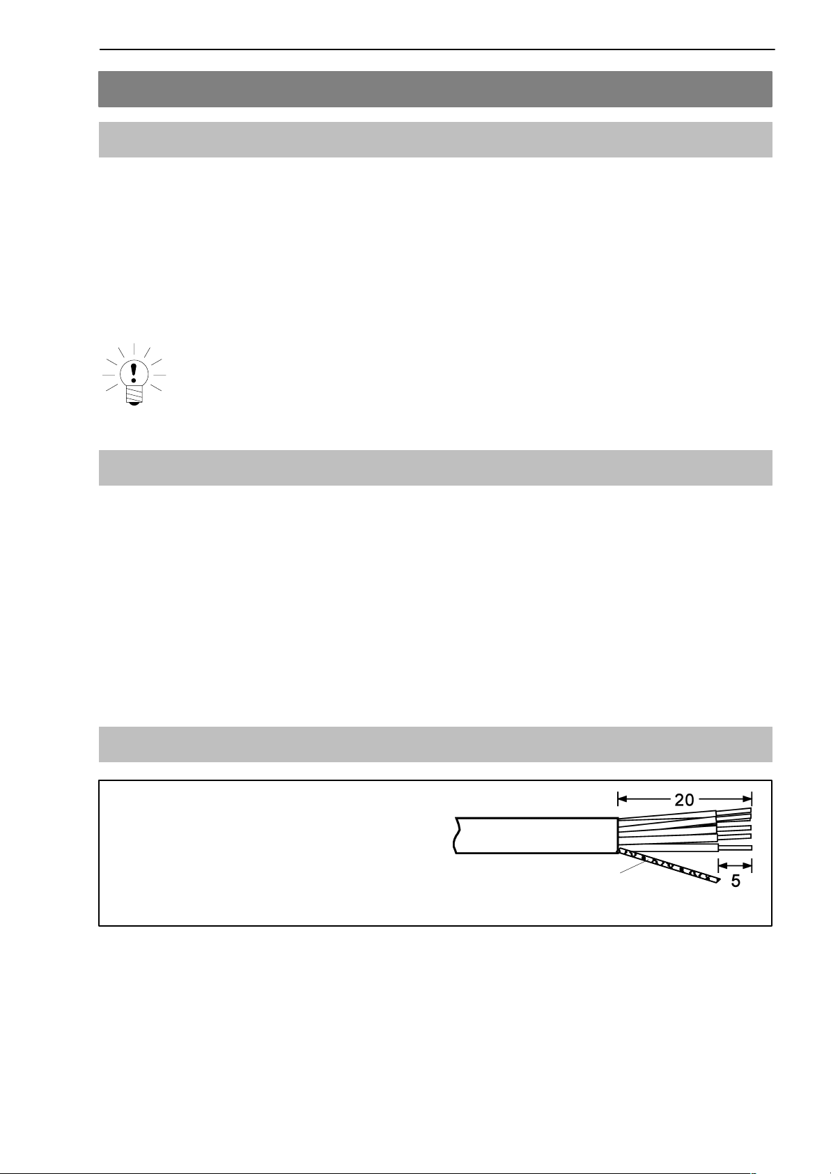
5.3 Cable preparation
• Remove the outer sheath about 20 mm.
• Twist braided shield.
• If necessary, remove the inner sheath.
• Strip the wire ends about 5 mm.
Shielding
• Connect the wires to the terminals.
HBMA2540-1.1 en/de
12
DC
Versorgungssp.ng
Shielding
+10...30 V
DC
TA (RA)
COM 1 Load cell
TB (RB)
Ground
GND
GND
RB
RA
DIS2116
Shielding
Shielding
Fig. 5.1:
Shielding
+10...30 V
Output voltage
+10...17 V*
* for C16i load cells
Output voltage
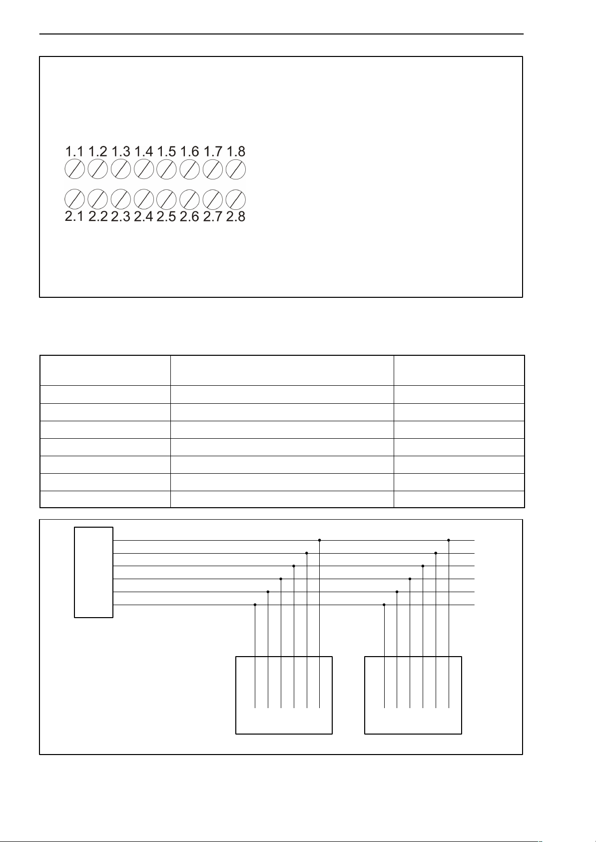
Position of connections on terminal block K1
5.3.1 Connecting DIS2116 with C16i
C16i
Cable core colours
Blue RS−485, transmitting line A (=T−) 1.7 RA (RX−)
Black RS−485, transmitting line B (=T+) 1.6 RB (RX+)
Green RS−485, receiving line A (=R−) 1.5 TA (TX−)
Gray RS−485, receiving line B (=R+) 1.4 TB (TX+)
White Power supply ground 2.4 GND
Red Power supply +, max. 17 V
1.7 RA (RX−)
1.6 RB (RX+)
1,5 TA (TX−)
1.4 TB (TX+)
2.3 UB(10...17 V)
2.4 GND
RS−485−4 wire DIS2116
Clamp K1
Screen connection 1.1
DC
2.3 UB
RS−485 / 4 wire bus
white
red
gray
green
black
white
red
GND
UB
gray
green
black
TB (TX+)
RB (RX+)
RA (RX−)
blue
TA (TX−)
GND
UB
RB (RX+)
blue
TB (TX+)
TA (TX−)
RA (RX−)
C16i ... C16i ...
Fig. 5.2: Cable assignment
HBM A2540-1.1 en/de
DIS2116
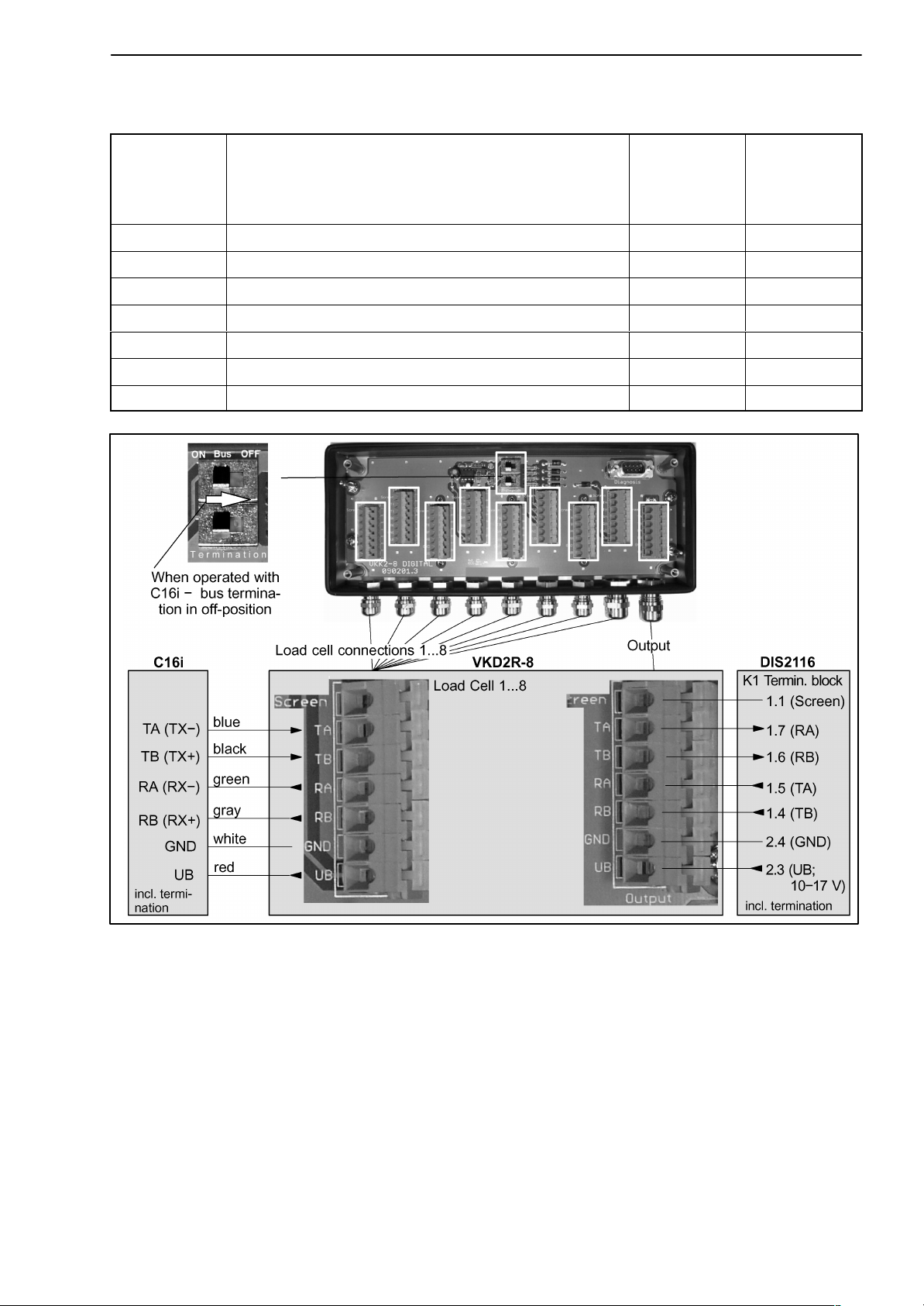
5.3.2 Connecting VKD2R-8 with DIS2116 and C16i
13
VK...
(input, Signals from
C16i)
TA RS-485, transmitting line A (=T−) TA 1.7 (RA)
TB RS-485, transmitting line B (=T+) TB 1.6 (RB)
RA RS-485, receiving line A (=R−) RA 1.5 (TA)
RB RS-485, receiving line B (=R+) RB 1.4 (TB)
GND Power supply ground GND 2.4
UB Power supply +, max. 17 V
RS-485 4-wire VK...
(output)
Screen connection Screen 1.1
DC
UB 2.3
DIS2116
(Clamp K1)
Fig. 5.3: Following the scheme of measuring chain C16i − VKD2R−8 − DIS2116
HBMA2540-1.1 en/de

14
DIS2116
5.4 Load cell connection
Digital load cells (C16i) can be connected to the DIS2116. An RS485 interface
is available for this purpose.
The RS485 interface can be used as a 4-wire (full duplex) or as a 2-wire (half
duplex) interface.
All digital load cells (e.g. C16i) have the address 31 as the factory setting. If
several load cells are connected to a scale, the load cell addresses must first
be changed. This setting is implemented in the parameter menu ”SCALE
CONFIGURATION” (see system CD)
NOTE
Call up the parameter menu ”SCALE CONFIGURATION” after connecting the
load cells.
5.5 Supply voltage
Terminal Function Comments
1.2 Supply voltage +10...30 VDC
1.3 Ground
1)
The supply voltage must be sufficiently filtered (rms value minus residual ripple > 10V).
1)
5.6 Voltage outputs
Terminal Function Comment
2.2 Output
voltage
10 ... 30 V
2.4 GND Ground
2.3 Output
voltage
10 ... 17 V
The input voltage 10 ...30 V is made available directly at the output
to supply digital load cells
This output is used to supply C16i load cells with a maximum
supply voltage of 17 V.
The input voltage is made available at the output up to a value of
17 V. The output is switched off at higher input voltages.
.
2.5 GND Ground
1.1, 1.8, 2.1,
2.8
HBM A2540-1.1 en/de
Shielding
DIS2116
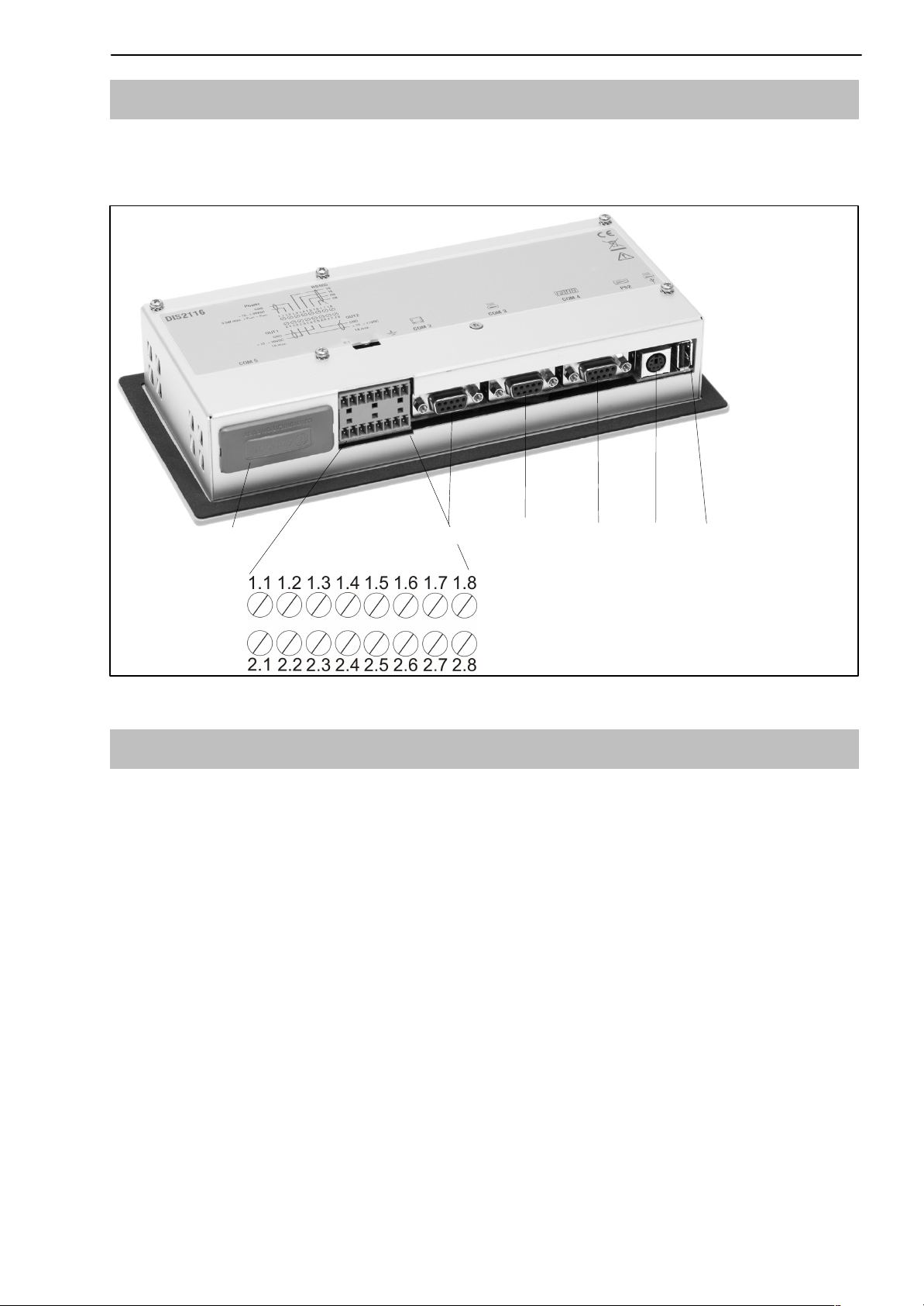
5.7 RS485 interface (Terminal block K1)
The DIS2116 is the master for the connection with the digital load cells (C16i,
measurement chain).
15
COM5 COM3 COM4 PS2
Fig. 5.4: Connection positions (back of device); assignment, see page 14
COM2
Terminal block K1
USB
5.8 Terminal block K1 assignments
The terminal block K1 has the following signals:
− Supply voltage input
− Supply voltage load cell output
− RS485 4−wire load cell interface
− CAN load cell interface (dependent on load cell) for future applications
HBMA2540-1.1 en/de
16
Terminal Signal Comments
1.1,1.8
2.1,2.8
1.2 Supply voltage 10...30 V
1.3 Supply voltage GND
1.4 COM1 load cell TB (RB) Serial interface
1.5 COM1 load cell TA (RA)
1.6 COM1 load cell RB
1.7 COM1 load cell RA
2.2 Voltage output 10...30 V Output voltage
2.3 Voltage output supply
2.4, 2.5 Voltage output GND
2.6 COM1 load cell CAN_low CAN interface
2.7 COM1 load cell CAN_high
Shielding
C16i
RS485
Only the terminals 1.4
and 1.5 must be used for
RS485 2−wire
= input voltage
10...17 V With input voltage
> 17 V this output does
not supply voltage
DIS2116
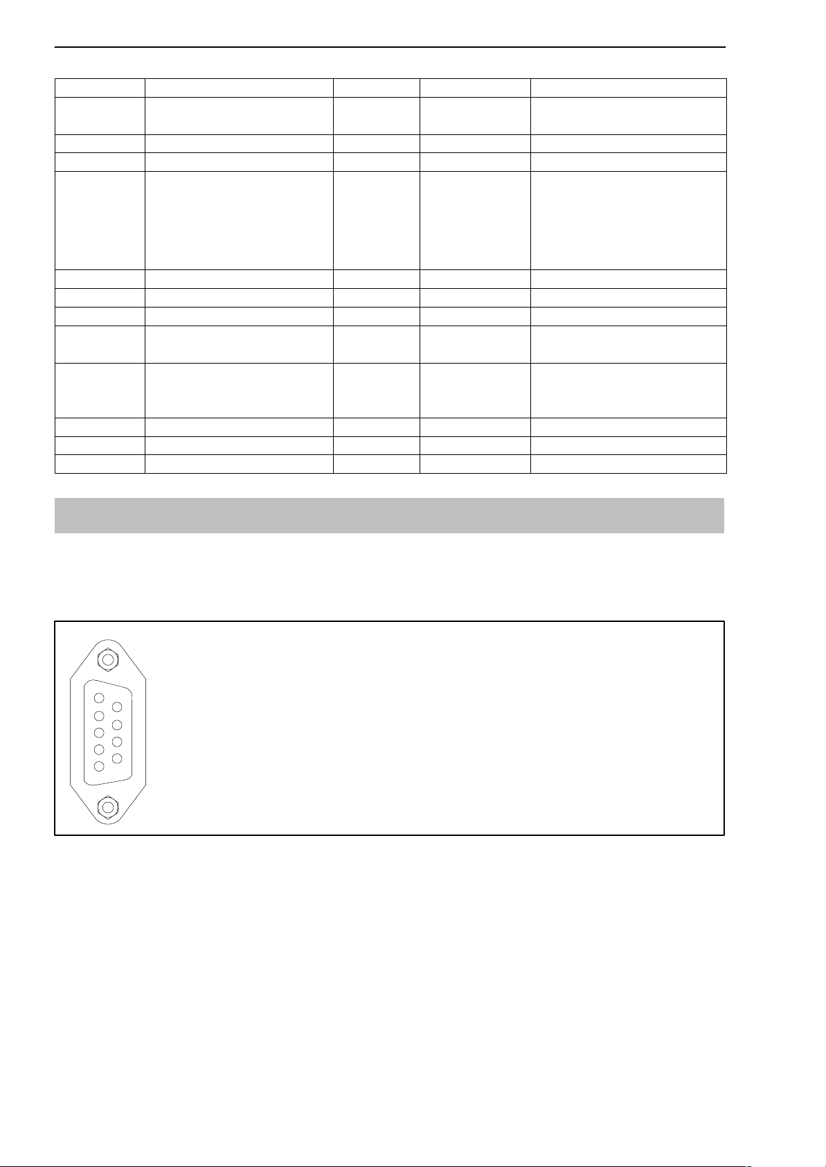
5.9 RS232 interface (COM2)
COM2 computer interface for connection to a PC via SUB−D 9-pin socket
The SUB-D socket is assigned so that a standard RS232 cable can be used.
1
2 RS232-TX
1
6
9
5
3 RS232-RX
4
50 V
6
7
8
HBM A2540-1.1 en/de
DIS2116
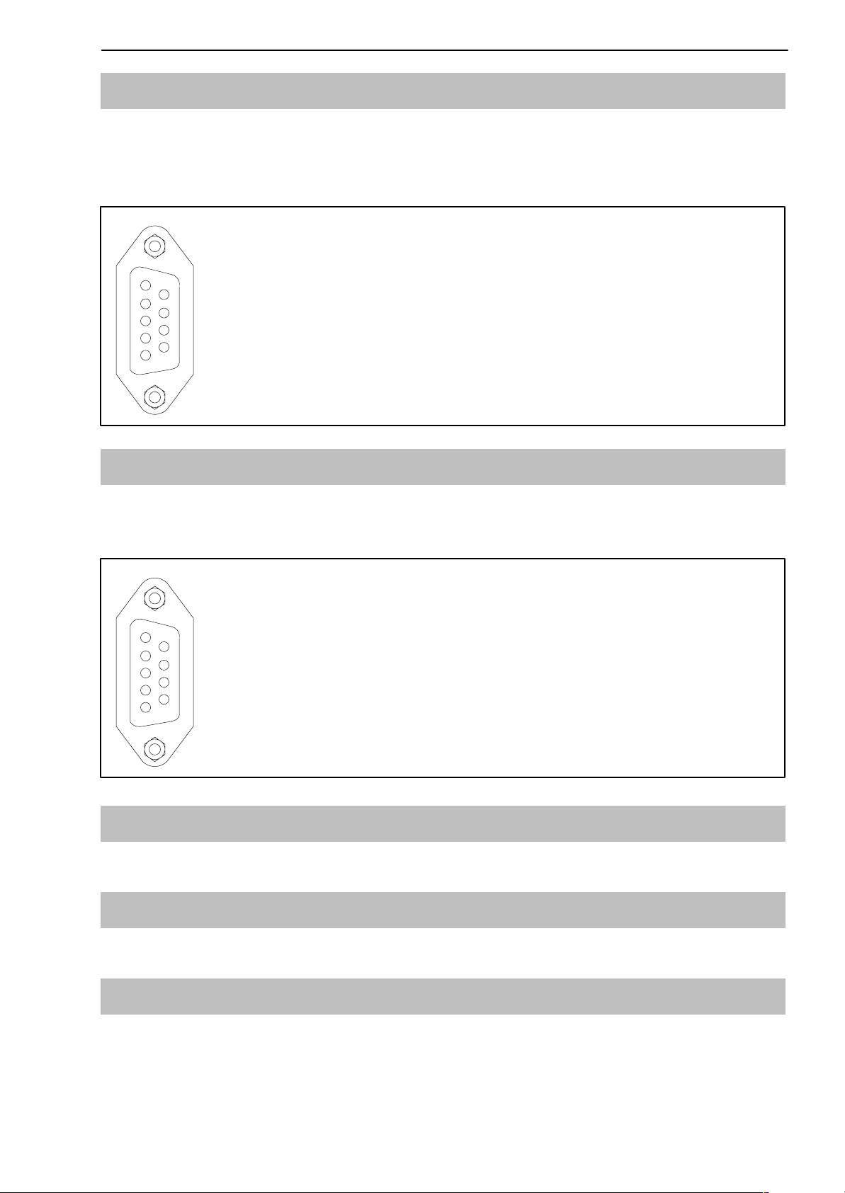
5.10 RS232 interface (COM3)
COM3 printer interface for connection of a serial printer via SUB−D 9-pin sokket. The SUB-D socket is assigned so that a standard printer cable can be
used.
1 −−−
2 RS232-TX
1
5
3 RS232-RX
6
4 DSR (DTR from printer)
50 V
6
9
7
8
9
17
5.11 RS-232 interface (COM4)
COM4 interface for connection of a second display via SUB−D 9-pin socket.
The SUB-D socket has the PC standard assignment.
1 −−−
2 RS232-TX
1
5
3 RS232-RX
6
4 DSR (DTR from second display)
50 V
6
9
7
8
9
5.12 PS2 keyboard interface
Input for connection of an external standard keyboard.
5.13 USB printer interface
USB host socket for connection of a printer.
5.14 Interface-Schnittstelle (COM5)
COM5 is set up as an optional interface for a fieldbus module.
The function and assignment is described together with the Anybus plug-in
module.
HBMA2540-1.1 en/de
18
6 Control and display functions
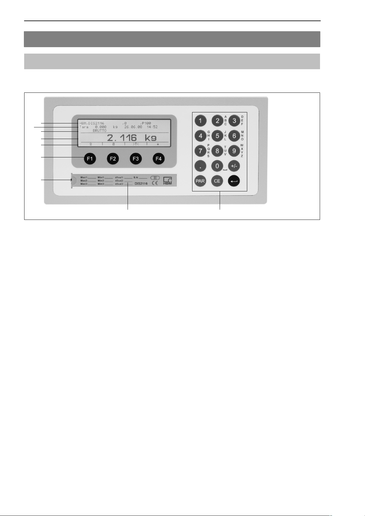
6.1 Device view
The front of the DIS2116 consists of the following elements:
1
2
3
4
5
6
7
DIS2116
98
Fig. 6.1:
DIS2116 front panel
1. Info line 1; configurable in the menu ”Display → Display line 1”
2. Info line 2; configurable in the menu ”Display → Display line 2”
3. Measurement status display
4. Measurement value display
5. Function line (meaning of function keys F1 ...F4)
6. Function keys F1 ... F4
7. Hidden pushbutton for access to the calibration menu. The pushbutton can
be accessed with a pointed object (when the label is removed). After calibration, the opening is sealed with the enclosed adhesive label or, for legalfor-trade applications, with the calibration label. Device calibration is protected during operation and can only be changed when this pushbutton is
actuated.
8. Inspection window for inserting a labeling strip (for scale type plate with calibration data, device name, etc.).
9. Keyboard for entering numbers and letters
The connections for serial interfaces and the terminals for the connection cables are located on the back of the device.
HBM A2540-1.1 en/de
DIS2116
6.2 Operator controls
• Key = Open parameter menu
19
• Key
= Cancel input, leave parameter menu without
accepting changes
• Key
• Keys F1...F4
= Accept input or setting and quit dialog
= The function of the keys is displayed by the text or
F1
the symbols in the function line (Fig. 6.2) in the display
• Hidden pushbutton for access to the calibration menu (see Fig. 6.1).
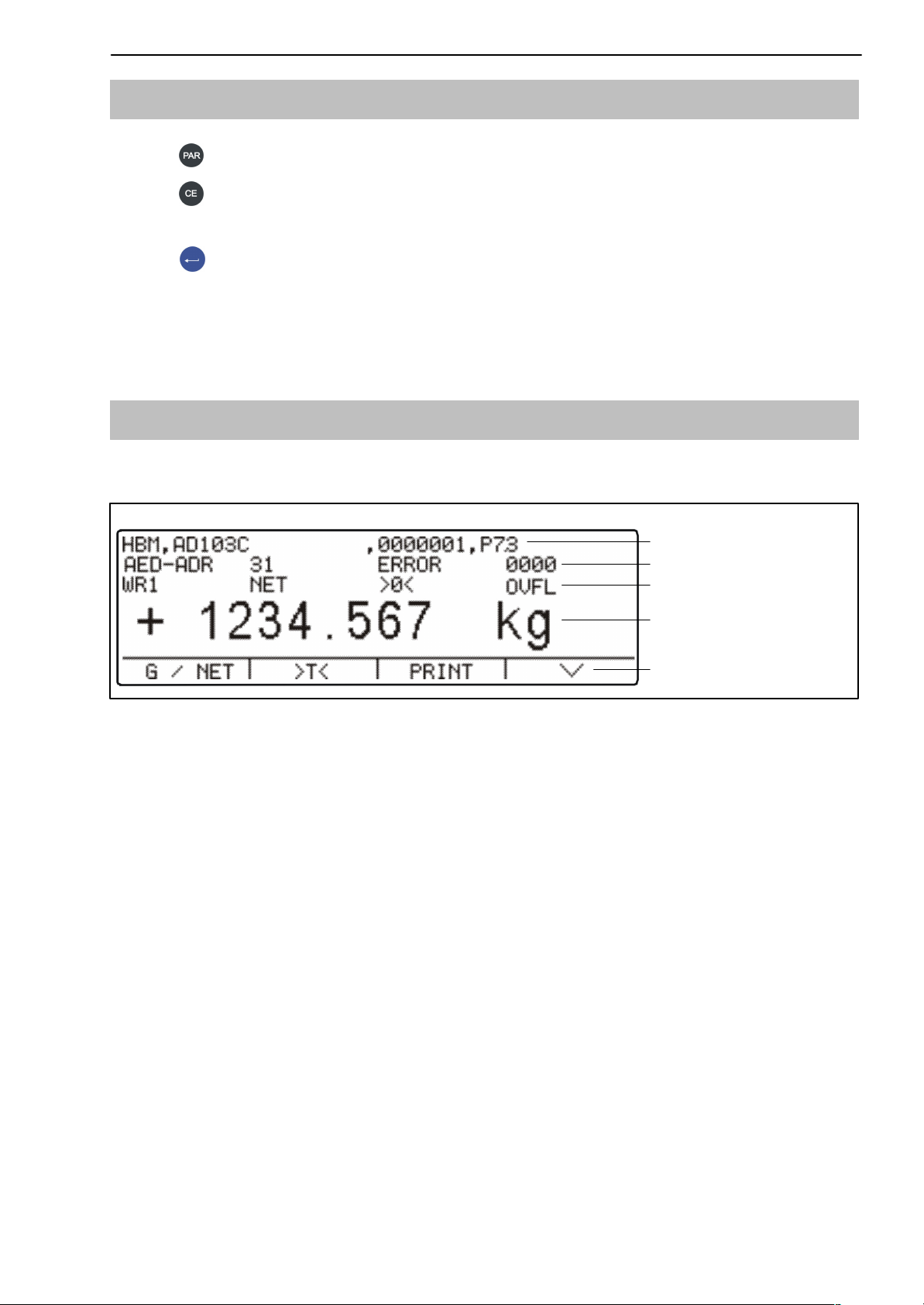
6.3 Display
The display consists of the following elements:
Info line 1
Info line 2
Status line
Measured
value display
Function
line
Fig. 6.2: Display
Info line 1 and Info line 2
The content of Info lines 1 and 2 can be set by the user.
(Menu ”DISPLAY→ DISPLAY LINE1” or ”DISPLAY → DISPLAY LINE2”)
HBMA2540-1.1 en/de

20
DIS2116
Status line
The status line is divided into 6 horizontal segments. The following symbols or
texts are displayed, where applicable:
• WR1 ... WR3: Displays the currently valid weighing range.
WR is not shown with just one weighing range
• GROSS, NET, NET PT Indicates whether a gross measured value, net
measured value or a net measured value where a
manual tare is calculated, will be displayed
• >0< Displayed when the measured value is 0 ± 0.25d
(true zero).
•
1,2 Displays the overshoot of the set limit value 1
and / or 2
• OVFL Overflow is displayed when at least one load cell
or the entire scale is loaded with more than 160 %
of its maximum capacity
• x10 10-fold resolution switched on
Measurement display
• The weight value is displayed with ± 7 digits with decimal point
• The physical unit is displayed with max. 4 characters
Display illumination
The LCD backlighting is always on once the power is connected
Display contrast
The LCD display contrast can be set in the menu ”DISPLAY → CONTRAST”
in 21 stages from −10 to +10. The lowest contrast is −10 and the highest +10.
HBM A2540-1.1 en/de
DIS2116
7 Basic scale functions
All device functions can be controlled in one or more of the following ways:
• Front control with 19 short-stroke keys. With the function keys F1 ... F4, the
meaning of the keys is displayed in the display function line.
• An external keyboard which can be connected via the PS2 input
• Connecting an external computer via the COM2 serial interface
The main scale functions (Gross/Net, Taring, Zero setting) are controlled via
the function keys F1...F4. For calibration and further device settings a menu is
called up with the key
not interrupted during parameter input, right up to exiting the menu. When
computer commands are used for control, measurement generally continues
without interruption. The exceptions to this are settling after filter selection and
power failsafe storage to the EEPROM.
(or F5 on the external keyboard) . Scale operation is
21
7.1 Zero setting the scale
Press the F4 key until the symbol >0< appears above the F3 key.
Press the F3 key to set the measurement value to zero.
The displayed gross value is zero immediately after zero setting.
MODE ³
LEGAL-FOR-TRADE
NO (not leg. f. trade) − 20 % + 20 %
OIML, NTEP − 2 % + 2 %
The % figures relate to the nominal weighing range (parameter ”SCALE PARAMETERS → PARAMETER → NOMINAL VALUE”)
Execution is dependent on standstill recognition (Chapter 7.9, page 25).
The net display is deactivated.
Range of zero setting, lower limit Range of zero setting, upper limit
NOTE
Zero setting is only possible when the function in the ”PARAMETER MENU →
FUNCTION KEYS → ZERO SETTING” is set to ACTIVE.
HBMA2540-1.1 en/de

22
DIS2116
7.2 Switching on and off
The device is switched on once the supply voltage is applied.
When the electronics are switched on, a BUS-SCAN is executed initially, i.e. a
check is made as to whether the load cells listed in the PARAMETER MENU
− SCALE CONFIGURATION are present.
During initial commissioning, all digital load cells have the same address 31
(factory setting). The load cells must be configured, before a scale adjustment
can be carried out.
With verified scales, a check is made as to whether the parameters in the load
cells have been changed. If the parameters in the load cells are no longer
identical to those during verification, an error message is displayed and no
measured values.
Connected load cells that are not entered in the ”PARAMETER MENU →
SCALE CONFIGURATION” are not taken into account.
During the BUS-SCAN:
• Information line 1 displays an identification string consisting of the manu-
facturer, TYPE, serial number and software version
• Information line 2 displays date and time
• Measured value status line displays the legal-for-trade counter status
(TCR) and whether the scale is legal for trade (LFT)
Zero is automatically set during initialization if this function is activated.
The actions carried out during initialization are displayed in clear text in the
measured value display and the initialization progress is shown by a moving
bar.
The scale must not be loaded before it is switched on.
The device is switched off by disconnecting the supply voltage from DIS2116.
HBM A2540-1.1 en/de

DIS2116
23
7.3 Gross/net selection
Press the F4 key until the symbol appears above the F2 key.
Every time the F2 key is pressed, the display changes between gross and net.
When selecting the net display, the last valid tare value is used again.
NOTE
Gross/net selection is only possible when the function in the ”PARAMETER
MENU → FUNCTION KEYS → GROSS/NET” is set to ACTIVE.
7.4 10-fold resolution
Press the F4 key until the display symbol x10 appears above the F2 key.
Every time the F2 key is pressed, 10x resolution is switched on/off. This mode
can be used for test purposes. The measured value is then displayed with a
factor 10 higher resolution.
NOTE
10-fold resolution is only possible when the function in the ”PARAMETER
MENU → FUNCTION KEYS → 10-FOLD RESOLUTION” is set to ACTIVE. If
the scale is set to legal-for-trade OIML or NTEP, 10-fold resolution can only be
switched on while the F2 key is pressed. When F2 is released, 10-fold resolution is switched off after 5 s.
7.5 Taring
Press the F4 key until the symbol >T< appears above the F3 key.
Pressing the F3 key stores the current gross value and deducts it from all the
subsequent weight values. The displayed (net) value is zero immediately after
taring. The tare value can be permanently displayed in the measurement value display, the setting must be made in the menu ”DISPLAY-DISPLAY-LINE1”
or ”DISPLAY-DISPLAY-LINE2”. The tare value can be read in the ”INFORMATION-TARE VALUE” menu item.
MODE ³
LEGAL-FOR-TRADE
NO (not legal for trade) −100 % 100 %
OIML, NTEP >0 100 %
Tare range, lower limit Tare range, upper limit
The % figures relate to the nominal weighing range (parameter ”SCALE PARAMETERS → PARAMETER → NOMINAL VALUE”)
HBMA2540-1.1 en/de

24
Execution is dependent on standstill recognition (Chapter 7.9, page 25).
Taring with this key overwrites any manual tare value that may have been ent-
ered previously (PT symbol is switched off).
Entering manual tare value
Pressing the F3 key for more than 2 s displays a window for input of a manual
tare value. Upon entry of a manual tare value, the net value plus manual tare
is displayed (NET PT).
NOTE
Taring and entry of a manual tare value is only possible when the function in
the ”PARAMETER MENU → FUNCTION KEYS → TARING” is set to ACTIVE.
DIS2116
7.6 Manual tare function
A manual tare value can be input in the parameter menu ”SCALE PARAMETERS-PARAMETER-MANUAL TARE VALUE” and the calculation of the manual tare value can be switched on/off in the parameter menu ”SCALE PARAMETERS-PARAMETER-MANUAL TARE MODE”, (see system CD).
When the ”Manual tare” function is active, the net value is formed by deducting a fixed tare value.
The ”G/N” key does not change the entered manual tare value.
The .PT. symbol in the display indicates that the net value has been formed by
deducting the manual tare value. This disappears after taring with the key F3
(”>T<”).
If the tare function was activated, it will also be activated once the device is
switched back on.
7.7 Zero on start-up
If this function is activated (parameter menu ”SCALE PARAMETERS → PARAMETER → ZERO ON START-UP”), the unloaded scale is automatically set to
zero when the DIS2116 is switched on (range of zero setting device ±2...20 %).
This takes into consideration the set standstill condition.
HBM A2540-1.1 en/de

DIS2116
7.8 Error displays
The permissible display range depends on the nominal value of the scale and
the set mode of operation (not legal for trade / OIML / NTEP).
25
MODE ³
LEGAL-FOR-TRADE
NO (not legal-for-trade) −160 % +160 %
OIML −2 % Nominal value + 9 d
NTEP −2 % Nominal value + 5 %
Lower display limit Upper display limit
The percentages relate to the nominal weighing range (”NOMINAL VALUE”
parameter)
The following error message appears in the display when the measured value
is
outside the maximum display range: −−−−−−−−−−−−−−−−−
Other errors are displayed as a four-digit code with explanation
(e.g. ERROR!
CODE 5700
No standstill
No measured value acquired
They should not occur in normal operation (see also Chapter 12.2, page 36).
7.9 Standstill recognition
The zeroing, taring and printing functions are only executed if the value in the
display is stable. This is known as standstill and is indicated by showing the
unit of measurement. The condition for standstill is that the value changes by
no more than a specific fluctuation limit per time unit. With fluctuating (wind)
loads or a very high scale resolution, it is quite possible that standstill will never be achieved. In this case, a more strongly damping filter or a lower resolution must be selected in the parameter setting.
The various options for standstill indication can be selected in the ”SCALE PARAMETERS-PARAMETER → STANDSTILL MON.” menu (see system CD).
It is also possible to switch off the standstill conditions (but not for legal-fortrade applications). The unit is always displayed when standstill monitoring is
switched off.
HBMA2540-1.1 en/de
26
F1+F2
F3
F4
Vehicle list
Yard list
Scroll to Level 2
8 Vehicle scale
8.1 Activate “VEHICLE SCALE” operating mode
DIS2116
Access: Key,
OPERATING MODE Standard*
MODE
I
Sub-menu explanation
Vehicle Activate vehicle operating mode
OPERATING MODE
(Enter)
If the DIS2116 has been set to legal-for-trade applications (OIML, NTEP), the
operating mode cannot be changed.
When the DIS2116 is set to vehicle scale with ”MODE−OPERATING MODE−VEHICLE”, the F1 to F4 function keys are assigned additional functions for vehicle
weighing. The assignment of keys F1 to F4 for vehicle weighing are displayed in
the measured value display function line by pressing F4 several times.
In the vehicle scale setting, there are three switchable function lines which
can be selected with the F4 key.
F1
Database
Function line for vehicle weighing
F2 F3 F4
→]
[→
↓ Level 1
8.2 Edit database
Press F4 until this function line appears
+
→] [→ ↓
F1 F2 F3 F4
Database Vehicle list
Check-in
Yard list
Check-out
Scroll to Level 2
The vehicle list is selected by pressing F1.
Note: Each time F1 is pressed, the mode switches between Edit database
and Vehicle selection.
Vehicle list: The following window appears on the screen:
Truck list − total
Search:
Truck Goods Procedure Date
F−RA 123
.....
o ± ° ²x
F1 F2 F3 F4
Gravel
....
Pickup
....
10.09.08
Function line
Keys
A maximum of 10 characters can be entered in the columns Truck, Goods and
Procedure. The date cannot be entered, the last date on which the vehicle
data was edited is displayed.
HBM A2540-1.1 en/de
DIS2116
w Vehicle search
There are two ways to search for a vehicle in the Truck list:
1. Search with keys ±(F2) °(F3)
The F2 key is used to search the entries in the “Truck” column alphabetically
from A³Z and F3 key from Z³A. The applicable vehicle is indicated by a
black bar.
2. Search using text
Use the keyboard to enter the number plate of the vehicle being sought. The
search starts with the first character entered. The first number plate that starts with
this character is now displayed in the first line under ”Truck” and is marked by a
black bar. The search is refined with every additional character that is entered.
If there is no vehicle that starts with the entered letter, the next vehicle is shown
that starts alphabetically with the letter after that entered.
27
The search text can be deleted with the F4 key (²x). The vehicle display
changes to match the remaining search text. If the search text is completely
deleted, the first vehicle in the list is displayed alphabetically.
directly opens the editor window of the selected vehicle, see Editing vehicle
data.
8.2.1 Editing vehicle data
The F1 ↵ key switches the function line mode between “Find vehicle” and
“Edit vehicle”.
+
Display illustration: “Edit vehicle data” function line
3/
x
0
Press the F2 key to open the editor window for the selected vehicle (marked
with a black bar).
Truck list 3/
Truck :F−RA 123 J
Goods :Gravel
Procedure :Pickup
Emptyw. :10.000 t
Max. weight :15.000 t
Min. weight :10.100 t
± ² ³ ²x
Display illustration: Editor window
HBMA2540-1.1 en/de
28
DIS2116
F1 moves the cursor to the required line
F2 moves the cursor left, F3 right
F4 deletes the line character by character from the right
The unit cannot be deleted, it corresponds to the unit set in the parameter
menu ”SCALE PARAMETERS−PARAMETER”.
8.2.2 x Delete vehicle
The F1 ↵ key switches the function line mode between “Find vehicle” and
“Edit vehicle”.
+
F1 F2 F3 F4
Display illustration: Edit vehicle data function line
3/
x
0
Press the F3 (x ) key to delete the selected vehicle (marked by a black bar)
from the database.
8.2.3 0 Create vehicle
The F1 ↵ key switches the function line mode between “Find vehicle” and
“Edit vehicle”.
+
F1 F2 F3 F4
Display illustration: “Edit vehicle data” function line
3/
x
0
Press the F4 (0) key to open an empty editor window. The entries can be
made here as described in Point 13.2.1 ”Edit vehicle data”.
The entered data is stored with the
Use the
key to close the window without saving the data.
key. An empty window cannot be saved.
8.3 Vehicle weighing mode Check-in/Check-out
In the vehicle weighing mode Check-in/Check-out, the weight determination
for the load is based on 2 measurements. The weight of the arriving truck is
recorded with Weighing1 and the weight of the departing truck with Weighing2. The difference is the weight of the loaded or unloaded material.
It is also possible to use the emtpy weight (pretare) stored with the truck data
as the weight for the arriving truck. The arriving truck then does not need to
drive onto the scale.
HBM A2540-1.1 en/de
 Loading...