

HBM CX22B-R Operating Manual
Operating Manual
English
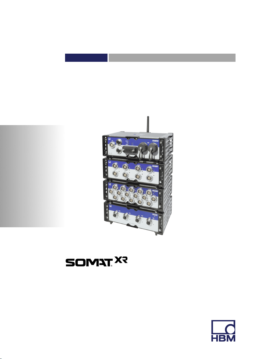
CX22B-R
catman Data Recorder

Hottinger Baldwin Messtechnik GmbH
Im Tiefen See 45
D-64239 Darmstadt
Tel. +49 6151 803-0
Fax +49 6151 803-9100
info@hbm.com
www.hbm.com
Mat.: 7-2002.4722
DVS: A4722-1.0 HBM: public
12.2017
E Hottinger Baldwin Messtechnik GmbH.
Subject to modifications.
All product descriptions are for general information only.
They are not to be understood as a guarantee of quality or
durability.

English
1 Safety instructions 5........................................
2 Markings used 13............................................
2.1 Markings used in this document 13..............................
2.2 Symbols on the module 14.....................................
2.3 Trademarks 15...............................................
3 Introduction 16..............................................
4 Connections and displays 18.................................
4.1 Voltage supply 19.............................................
4.2 Ground connection and grounding 20............................
4.3 Connection of MX modules 20..................................
4.4 Communication with the Data Recorder 21.......................
4.5 USB 2.0 interfaces 22.........................................
4.6 Digital inputs and outputs 22...................................
4.7 LED displays 23..............................................
5 Connecting measurement modules 26........................
6 Operating the Data Recorder 29..............................
6.1 Operation with monitor and keyboard/mouse 29...................
6.2 Operation via a PC 31.........................................
6.2.1 A direct Ethernet line between PC and Data Recorder 32..........
6.2.2 Connection via a network 38...................................
6.2.3 Connection via WLAN 39......................................
6.2.4 Connection via a tablet 41.....................................
6.3 Connection via remote desktop 42..............................
6.4 Detecting and resolving connection problems 47..................
6.5 Using Ethernet and WLAN in parallel 48.........................
6.6 UPS settings and shut‐down 49.................................
CX22B-R A4722-1.0 HBM: public 3

7 The CX22B‒R Data Recorder start screen 51...................
8 The first DAQ job with catman[EASY 53......................
8.1 Creating a DAQ job 53........................................
8.2 Transferring data/files to the PC 58..............................
8.3 Data analysis 60..............................................
8.4 Monitoring functionality 61.....................................
9 Configuring the CX22B‒R for self-contained measurements 64.
10 Saving data on the Data Recorder 68..........................
10.1 Memory partitioning 68........................................
10.2 Memory performance 69.......................................
10.3 EWF, safeguarding your settings against change 69...............
11 Operating the CX22B-R as gateway 71........................
11.1 Description 71................................................
11.2 Activate/deactivate gateway mode 71...........................
11.3 Connect to a QuantumX module behind a CX22B-R 72............
11.4 Performances 74.............................................
12 System settings, update and recovery 75......................
12.1 Installing drivers 75...........................................
12.2 Changing system settings (Settings) 76..........................
12.3 Updating the software 78......................................
12.4 System restoration (Recovery) 78...............................
12.5 Potential sources of error and remedial action 79..................
13 FCC (USA) and CI (Canada) statement 80......................
14 Waste disposal and environmental protection 82..............
15 Index 84....................................................
4 A4722-1.0 HBM: public CX22B-R

1 Safety instructions
Intended use
The SomatXR Data Recorder CX22B-R is to be used
exclusively for measurement tasks and directly related
control tasks within the ratings stated in the "Specifica
tions" section and under the conditions given in the same
section. Any other use is not appropriate.
Proper and safe operation requires proper transportation,
correct storage, siting and mounting, and careful opera
tion. Everyone involved with siting, starting up, or operating
the module must have read and understood the operating
manual and in particular the technical safety instructions.
In the interest of safety, the module should only be oper
ated by qualified personnel (see below) and as described
in the operating manual.
It is also essential to comply with the legal and safety
requirements for the application concerned during use.
The same applies to the use of accessories.
Safety instructions
Notice
If the measurement module is not used as intended or is
used outside the ratings, the protection provided by the
module may be impaired.
CX22B-R A4722-1.0 HBM: public 5
Safety instructions
Installation of the module(s)
SomatXR modules are IP65/IP67 rated. They can be
used outdoors without any special protection. In dirty
environments, protective caps should be attached to con
nectors that are not being used to allow later plug inser
tion.
SomatXR modules can be used as tabletop unit but also
mounted on a surface or in a box.
Please consider following conditions at the place of
installation:
S Observe the maximum permissible ambient tempera
tures given in the specifications.
S Minimize device exposure to direct sunlight in hot
operating environments.
A module must not be connected directly to a power sup
ply network. The maximum permissible supply voltage is:
Module Power supply
CX22B-R 10 VDC … 30 V
CX23‐R 10 VDC … 30 V
EX23‐R 10 VDC … 36 V
MX modules 10 VDC … 30 V
DC
DC
DC
DC
Notice
The module must not be connected directly to the power
supply system.
6 A4722-1.0 HBM: public CX22B-R

Safety instructions
Tip
When modules are installed in a vehicle, we recommend
connection to a separate battery or integration of an unin
terruptible power supply (UPS), as battery voltage is par
ticularly likely to fall below 10 V when a combustion
engine starts up, which would automatically cause the
modules to restart.
Maintenance, repair and modification
The modules are maintenance-free.
Only trained and qualified personnel who are authorized
to do so by HBM are allowed to open the module. Before
opening the module, disconnect all connections. Opera
tion when open is not allowed. Once the device has been
opened, it must be professionally inspected in accor
dance with EN 60950, before starting it up again.
The module is delivered from the factory with a fixed
hardware and software configuration. Changes can only
be made within the possibilities documented in the man
ual.
The module must not be modified from the design or
saftey engineering point of view except with our express
agreement. In particular, any repair or soldering work on
printed wiring boards (exchanging components) is prohib
ited. When exchanging complete subassemblies, use
only original parts from HBM.
Following modules contain a battery to buffer memory
content and guarantee an uninterruptible operation of the
time basis:
- CX22B-R: BR2330A/FAN (soldered)
- CX23-R: BR2477 (soldered)
CX22B-R A4722-1.0 HBM: public 7

Safety instructions
Only trained and qualified personnel who are authorized
to do so by HBM are allowed to change these batteries.
Notice
If the module is opened, modified, or inexpertly repaired,
the protection provided by the module may be impaired.
Cleaning
Please note the following when cleaning the housing:
► Before cleaning, disconnect all connections.
► Clean the housing with a soft, slightly damp (not wet!)
cloth. Never use solvent, as this could damage the
label or the housing.
► Do not apply high water pressure to the unit for clean
ing.
► Give the module sufficient time to dry before starting it
up again.
General dangers of failing to follow the safety
instructions
The module is a state of the art device and, as such, is
fail-safe. The module may give rise to further dangers if it
is inappropriately installed and operated by untrained per
sonnel. Any person instructed to carry out installation,
commissioning, maintenance or repair of the module
must have read and understood the User Manuals and in
particular the technical safety instructions.
Product liability
In the following cases, the protection provided for the de
vice may be adversely affected. Liability for device func
tionality then passes to the operator:
8 A4722-1.0 HBM: public CX22B-R

Safety instructions
S The device is not used in accordance with the operat
ing manual.
S The device is used outside the field of application
described in this chapter.
S The operator makes unauthorized changes to the
device.
Working safely
► When the module is unpacked, check it for visible
signs of damage. If damge has occurred, the module
must not be operated.
Error messages should only be acknowledged once the
cause of the error is removed and no further danger
exists.
When modules are in operation, the following measures
need to be taken to reduce the risk of incineration at sur
faces:
- Operating personnel must be advised of the possi
bility of incinerations when touching the surface of
the module.
- Operating personnel must be instructed to touch
the surface of the module only with appropriate pro
tective equipment (adequate protective gloves).
The equipment complies with the EMC standards of EN
61326-1 / EN 61326-2-x. These standards define emis
sion limits and immunity requirements for multiple envi
ronments.
With respect to emissions, the standards contain limits
for industrial (class A) and residential / commercial (class
B) environments. The standard herein references CISPR
11:2009+A1:2010.
CX22B-R A4722-1.0 HBM: public 9

Safety instructions
With respect to immunity, the standards contain limits for
electromagnetically protected (lowest requirements), gen
eral and industrial (highest requirements) environments.
The SomatXR modules listed in the declaration of con
formity conform to the requirements for:
- Emissions: Class A
- Immunity: Industrial
The SomatXR series and its modules are intended for
use in an industrial environment. When used in residen
tial or commercial environments, additional arrangements
may be required to limit electromagnetic emissions.
The supply connection, as well as the signal and sense
leads, must be installed in such a way that electromag
netic interference does not adversely affect device func
tionality. (HBM recommendation: "Greenline shielding
design," downloadable from the Internet at
http://www.hbm.com/greenline.)
The measurement module and devices used in automa
tion equipment must be covered over in such a way that
adequate protection or locking against unintentional actu
ation is provided (e.g. access checks, password protec
tion, etc.).
For those measurement modules operating in networks,
safety precautions must be taken in terms of both hard
ware and software, so that a line break or other interrup
tions to signal transmission do not cause undefined
stated or loss of data in the autmation device.
After making settings and carrying out activities that are
password-protected, ensure that any controls that may
be connected remain in a safe condition until the switch
ing performance of the module has been tested.
An emergency and incident plan must be prepared,
decribing the responses to minimize risk in the event of
10 A4722-1.0 HBM: public CX22B-R

Safety instructions
an emergency or incident. Operating personnel must be
familiar with this plan, which must be accessible to them.
Notice
In the following situations, the module must be shut down
and secured to prevent inadvertent operation:
- visible signs of damage to the module
- (audibly) loose parts in the module
- the module no longer works
Qualified personnel
This device is only to be installed and used by quali
fied personnel strictly in accordance with the specifi
cations and with the safety rules and regulations
which follow.
Qualified personnel means persons entrusted with siting,
mounting, starting up and operating the product who
possess the appropriate qualifications for their function.
This includes people who meet at least one of the three
following requirements:
S Knowledge of the safety concepts of automation tech
nology is essential and as project personnel, they
must be familiar with these concepts.
S As automation plant operating personnel, they have
been instructed how to handle the machinery. They
are familiar with the operation of the modules and
technologies described in this documentation.
S As system startup engineers or service engineers,
they have successfully completed the training to qual
ify them to repair the automation systems. They are
also authorized to activate, ground and label
CX22B-R A4722-1.0 HBM: public 11

Safety instructions
circuits and equipment in accordance with safety
engineering standards.
It is also essential to comply with the legal and safety
requirements for the application concerned during use.
The same also applies to the use of accessories.
Maintenance and repair work on an open device with the
power on may only be carried out by trained personnel
who are aware of the dangers involved.
12 A4722-1.0 HBM: public CX22B-R
Markings used
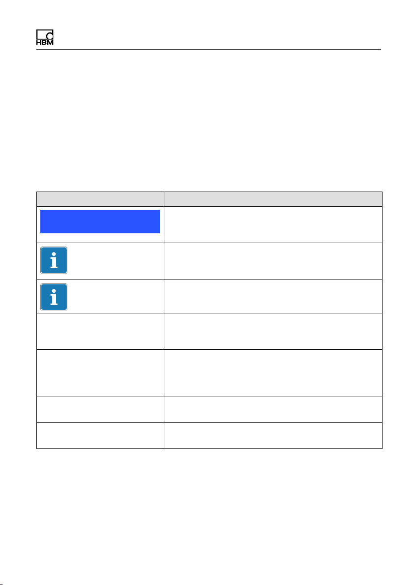
2 Markings used
2.1 Markings used in this document
Important instructions for your safety are specifically
identified. It is essential to follow these instructions, in
order to prevent accidents and damage to property.
Symbol Significance
Notice
Important
Tip
Emphasize
See…
Device -> New Bold text indicates menu items, as well as dialog and
Data rate Bold text in italics indicates inputs and input fields in
►
This marking draws your attention to a situation in
which failure to comply with safety requirements can
lead to accidents or damage to property.
This marking draws your attention to important infor
mation about the product or about handling the prod
uct.
This marking indicates application tips or other infor
mation that is useful to you.
Italics are used to emphasize and highlight text and
identify references to sections, diagrams, or external
documents and files.
window headings in the program environment.
Arrows between menu items indicate the sequence in
which the menus and sub-menus are called up
the user interfaces.
Instructions are marked by a small, right-pointing
triangle.
CX22B-R A4722-1.0 HBM: public 13
Markings used
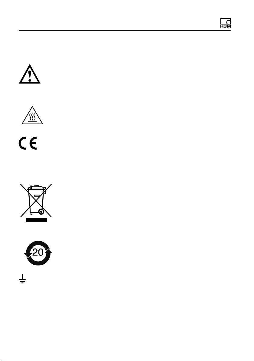
2.2 Symbols on the module
Caution
To indicate that caution is necessary when operating the
device and the details in the operating manual need to be
taken into account, when operating the module.
Caution hot surface
To indicate that the marked item can be hot and should
not be touched without taking care.
CE mark
The CE mark enables the manufacturer to guarantee that
the product complies with the requirements of the rele
vant EC directives (the Declaration of Conformity can be
found on the HBM support website www.hbm.com.
Statutory waste disposal mark
see Chapter, Chapter 14.
Statutory mark of compliance with emission limits in
the electonic equipment supplied to China
see Chapter, Chapter 14.
Connection for functional earth
If necessary, integrate the module into your functional
grounding via this connection, so that interference cur
rents can be sicharged and interference signal injection
prevented.
14 A4722-1.0 HBM: public CX22B-R

Markings used
2.3 Trademarks
catman is a registered trademark of Hottinger Baldwin
Messtechnik GmbH.
All trademarks and brands used in this document are
belonging to the respective product or the manufacturer/
owner. Hottinger Baldwin Messtechnik GmbH does not
lay claim to any other than their own trade names/trade
marks.
CX22B-R A4722-1.0 HBM: public 15

Introduction
3 Introduction
This manual is intended to support you in making the
basic settings of your SomatXR Data Recorder
CX22B-R.
The CX22B‒R Data Recorder has an integrated WLAN
module. An antenna can be screwed on via the standard
ized SMA socket (RF coax type). A bendable antenna is
included with the product.
All measurement technology settings are implemented
using catmanEASY, which has an extensive online
Help.
This manual shows you:
S How to start up the module.
S What can be connected and what to look out for.
S How to start your first measurement and DAQ jobs
and how to get to the measurement data.
The following documentation is also available:
S SomatXR MX modules operating manual with the pin
assignment of the MX modules
S Data sheets
S Online Help in the catmanEASY and MX-Assistant
software
S Tips for use on topics such as GPS, camera or how to
connect wheel force transducers like Kistler RoaDyn.
The device is a SomatXR module with the "Windows
Embedded‐8 StandardTM" operating system and
pre-installed catmanEasy software from HBM. Most of
the software functionality is described in the data sheet.
Interfaces on the back of the Data Recorder:
16 A4722-1.0 HBM: public CX22B-R

Introduction
S 2 x FireWire (ODU socket, 4-pin) for connecting
SomatXR or QuantumX modules.
S Voltage supply (ODU socket, 4-pin)
S WLAN for a sma antenna
The following interfaces and options can be found on the
front:
S 2 x Gigabit Ethernet 2 x USB 2.0, 1 x DVI‐D
S 3 x digital inputs and 3 x digital outputs
CX22B-R A4722-1.0 HBM: public 17
Connections and displays
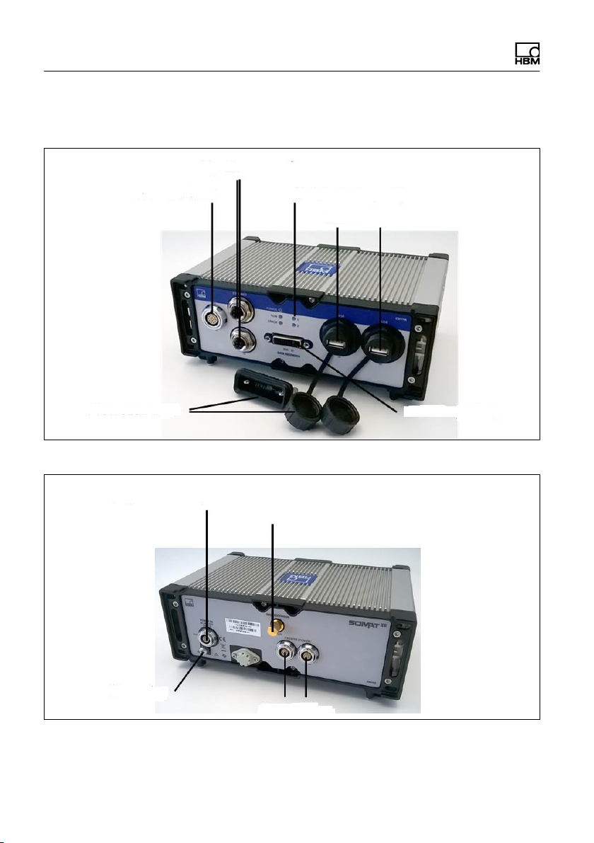
4 Connections and displays
2x Gigabit Ethernet
Status LEDs (1+2)
Fig. 4.1 CX22B‒R connections on the front
2x USB 2.0
Monitor (DVI-D)Protection caps
Supply voltage
DC 10 V … 30 V
Grounding
WLAN antenna
2x Fire Wire
Fig. 4.2 CX22B-R connections on the back
18 A4722-1.0 HBM: public CX22B-R

Connections and displays
4.1 Voltage supply
Apply a supply voltage of DC 10 - 30 V to connector
X104 (see Fig. 5.1). Use a voltage supply with sufficient
power, in case the MX modules connected to the
CX22B‒R or devices such as GPS sensors, cameras or
data memory directly connected to the unit also need to
be supplied with power.
The DC voltage supply must be a SELV voltage supply,
meeting the requirements of IEC / EN / DIN EN 609501.
The supply voltage must be protected by an adequate
DC fuse (e.g. LITTELFUSE KLKD 6, LFPHV001) with a
maximum current of 5 A.
CX22B-R has a integrated uninterruptible power supply
(UPS) to buffer short voltage drops. It also allows a regu
lar storing of the measurement data respectively a proper
shut-down of the module.
When running on the UPS, no power will be provided to
MX modules connected via FireWire. If needed, the con
nected MX modules need a separate UPS for buffering.
Details about the UPS and its settings can be found in
chapter 6.6.
HBM offers the NTX002 power supply for laboratory or
general steady-state operation. On the primary side, this
provides a selection of international connector types and
24 V and 30 watts on the secondary side. A CX22B‒R
and one additional MX module can be supplied in this
way. See the respective module data sheets for precise
details of performance.
The Data Recorder can also be supplied with voltage by
a (FireWire) module group.
CX22B-R A4722-1.0 HBM: public 19

Connections and displays
The data recorder hosts a small buffer battery. This
battery keeps date and time during power interruptions.
The battery shall only be replaced by HBM service.
4.2 Ground connection and grounding
Lay the signal and data leads separately from currentcarrying power lines. Cable ducts made of sheet metal
with an internal partition are ideal.
If there are differences in potential in or to the connected
measurement system, you must install a potential equal
ization line (recommended value: highly flexible stranded
wire, line cross-section 10mm2).
4.3 Connection of MX modules
Important
The simplest way to connect measurement modules to
the CX22B‒R Data Recorder is via FireWire, or alterna
tively via Ethernet.
FireWire has the following advantages:
S Voltage supply, time synchronization, data communi
cation and real time in one cable and thus little effort
and low cost
S Every module has 2 FireWire connections, so flexible
topologies are possible: star, line or even hybrids with
an appropriate hub, also supplied with power via
FireWire.
Ethernet has the following advantages
20 A4722-1.0 HBM: public CX22B-R

Connections and displays
S The components used are readily available on the
market
S Up to 100 m line lengths to the module
S Synchronization via NTP or PTPv2 (IEEE1588:2008)
when using an appropriate switch (e.g. EX23-R)
S Wireless connection of modules via WLAN
4.4 Communication with the Data Recorder
You can work with the Data Recorder in the following
way:
S Directly connected peripherals
- Monitor or touchscreen (DVI)
- Mouse and keyboard to USB
S Access via a PC or tablet by means of a "remote
desktop connection" (standard in Windows)
- Direct connection via an Ethernet patch cable
- Wireless connection (WLAN)
- In a network (LAN)
- Remote access via an Internet connection and a
mobile services provider using a mobile services
gateway
CX22B-R A4722-1.0 HBM: public 21

Connections and displays
4.5 USB 2.0 interfaces
Devices such as a keyboard, mouse, monitor, printer, as
well as GPS sensors or data memory such as a USB
flash drive, can be connected.
Tips for use are available for the connection of GPS sen
sors via USB.
Notice
If you have to install device drivers, please note Section
12.4.
4.6 Digital inputs and outputs
Three inputs and three outputs are available at connector
X6 (ODU 14 pin). The inputs and outputs are TTL-com
patible (-0.5 to 5.5V).
Inputs
The level for the inputs is 5 volts in the open state
(HIGH), as it is pulled up to HIGH by a pull-up resistor
(active LOW). The maximum LOW level is 0.7 volts and
the minimum HIGH level is 4 volts.
Outputs
The level for the outputs is 5 volts (HIGH), when the cor
responding output is set, otherwise 0 volts (LOW). The
line lengths at the outputs must not exceed 3 m. Maxi
mum output current is 1 mA.
22 A4722-1.0 HBM: public CX22B-R
Connections and displays
Tip
At the start of a DAQ job, outputs are reset to LOW if in
catman[EASY, in the options for the CX22B‒R (system
group), you activate the setting Reset all CX22B‒R
digital outputs at the start of a DAQ job.
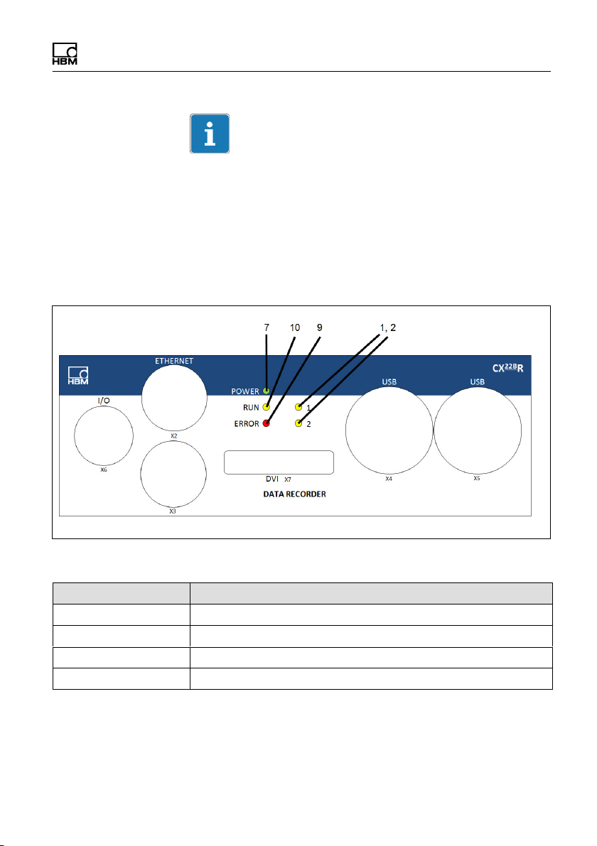
4.7 LED displays
Fig. 4.3 Position of the LEDs
LED Function
1, 2 Operating condition status
7 POWER = Module LED
9 ERROR LED
10 RUN = RECORDING LED
CX22B-R A4722-1.0 HBM: public 23
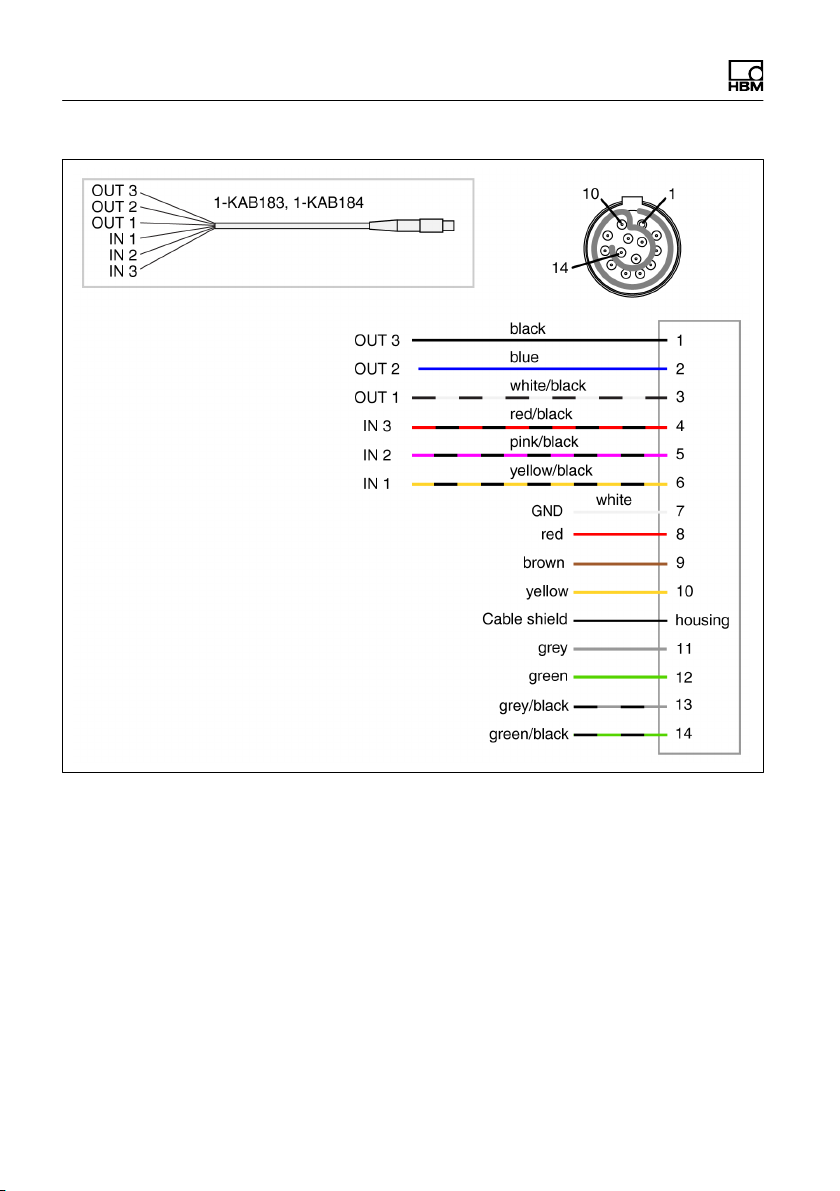
Connections and displays
Fig. 4.4 Pin assignment digital In ‐ and Output
24 A4722-1.0 HBM: public CX22B-R

Connections and displays
Module LED
The module LED (see Fig. 4.1 on Page 18) lights up
green when the CX22B‒R power supply is present. The
module requires approx. 1 minute after switch-on before
the boot process is complete.
Status LEDs for the operating status
The "RUN" LED
shows continuously yellow when measurement data
are being recorded. If a start trigger was set, the LED
flashes yellow while waiting for the trigger event.
The "ERROR" LED
lights up red if the software detects an error, e.g.
when no connection could be set up to the devices at
the start of the project. The LED flashes if the avail
able free memory drops below 1 GByte.
All Status LEDs can also be triggered via Limit values
and events in catman EASY. To do this select Set dig
ital output: CX22B-R digital output in the Configure
limit value and event monitoring dialog and enter the
required LED in Bit/Condition.
CX22B-R A4722-1.0 HBM: public 25

Connecting measurement modules
5 Connecting measurement modules
The simplest way to connect SomatXR or QuantumX
modules to the Data Recorder is via FireWire. Connect
cable 1-KAB272-x to any of the Data Recorder's connec
tions and the other end to connection X102 of the near
est measurement module.
Then keep threading: connection X102 to X101 of the
second measurement module, etc. Remember the maxi
mum current of 1.5 A. As a rule, you must introduce a
voltage supply again after 3 modules. You can also con
nect measurement modules at the second FireWire con
nection X102 of the CX22B-R.
In the configuration shown below, the module supply volt
age is looped through via FireWire (max. 1.5 A via
FireWire). The power consumption of a module is ex
plained in the data sheet.
You can connect up to 12 modules to the CX22B‒R Data
Recorder via FireWire, with a supply feed required for at
least every 3rd module. The supply voltages must have
approximately the same voltage level. The general
SomatXR MX modules operating manual contains more
detailed data on this.
Notice
If the modules are used in a vehicle, we recommend to
supply the connected MX modules via a separate battery
or a UPS (e.g. UPX002). The integrated UPS of the
CX22B-R will not power the connected modules. In case
of voltage drops the measurement will stop if the MX
modules are not buffered.
26 A4722-1.0 HBM: public CX22B-R
 Loading...