

Page 1
Operating Manual | Bedienungsanleitung
English Deutsch
CX22B / CX22B-W
Data Recorder - Datenrekorder
Page 2

Hottinger Baldwin Messtechnik GmbH
Im Tiefen See 45
D-64239 Darmstadt
Tel. +49 6151 803-0
Fax +49 6151 803-9100
info@hbm.com
www.hbm.com
Mat.: 7-2001.3169
DVS: A3169-8.0 HBM: public
08.2017
E Hottinger Baldwin Messtechnik GmbH.
Subject to modifications.
All product descriptions are for general information only.
They are not to be understood as a guarantee of quality or
durability.
Änderungen vorbehalten.
Alle Angaben beschreiben unsere Produkte in allgemeiner
Form. Sie stellen keine Beschaffenheits- oder Haltbarkeits
garantie dar.
Page 3
Operating Manual | Bedienungsanleitung
English Deutsch
CX22B / CX22B-W
Data Recorder
Page 4

English
1 Safety instructions 4........................................
2 Markings used 10............................................
2.1 The markings used in this document 10..........................
2.2 Symbols on the module and their meaning 11....................
3 Introduction 13..............................................
4 Connections and displays 15.................................
4.1 Voltage supply 17.............................................
4.2 Ground connection and grounding 18............................
4.3 Connection of QuantumX modules 18...........................
4.4 Communication with the Data Recorder 19.......................
4.5 Connector strip for backplane integration 20......................
4.6 USB 2.0 and USB 3.0 interfaces 20.............................
4.7 RS232 interface 20...........................................
4.8 Digital inputs and outputs 21...................................
4.9 START/STOP button 21.......................................
4.10 LED displays 22..............................................
5 Connecting QuantumX modules 27...........................
6 Operating the Data Recorder 30..............................
6.1 Operation with monitor and keyboard/mouse 30...................
6.2 Operation via a PC 31.........................................
6.2.1 A direct Ethernet line between PC and Data Recorder 33..........
6.2.2 Connection via a network 39...................................
6.2.3 Connection via WLAN 40......................................
6.2.4 Connection via a tablet 42.....................................
6.3 Connection via remote desktop 43..............................
6.4 Detecting and resolving connection problems 48..................
6.5 Using Ethernet and WLAN in parallel 49.........................
2 A3169-8.0 HBM: public CX22B / CX22B-W
Page 5

7 The CX22B‒W Data Recorder start screen 51..................
8 The first DAQ job with catman[EASY 53......................
8.1 Creating a DAQ job 53........................................
8.2 Transferring data/files to the PC 58..............................
8.3 Data analysis 60..............................................
8.4 Monitoring functionality 61.....................................
9 Configuring the CX22B‒W for self-contained measurements 63.
10 Saving data on the Data Recorder 66..........................
10.1 Memory partitioning 66........................................
10.2 Removing and inserting the CFast memory card 68...............
10.3 Memory performance 69.......................................
10.4 EWF, safeguarding your settings against change 70...............
11 Operating the CX22B/CX22B-W as gateway 71.................
11.1 Description 71................................................
11.2 Activate/deactivate gateway mode 71...........................
11.3 Connect to a QuantumX module behind a CX22B-W 72............
11.4 Performances 74.............................................
12 System settings, update and recovery 75......................
12.1 Installing drivers 75...........................................
12.2 Changing system settings (Settings) 76..........................
12.3 Updating the software 77......................................
12.4 System restoration (Recovery) 78...............................
12.5 Potential sources of error and remedial action 78..................
13 FCC (USA) and CI (Canada) statement 80......................
14 Waste disposal and environmental protection 82..............
15 Index 83....................................................
CX22B / CX22B-W A3169-8.0 HBM: public 3
Page 6

Safety instructions
1 Safety instructions
Appropriate use
The QuantumX Data Recorder is to be used exclusively
for measurement tasks and directly related control tasks
within the application limits detailed in the specifications.
Use for any purpose other than the above is deemed to
be non-designated use.
In the interests of safety, the module should only be oper
ated as described in the Operating Manuals. It is also es
sential to comply with the legal and safety requirements for
the application concerned during use. The same applies to
the use of accessories.
Each time you start up the module, you must first run a
project planning and risk analysis that takes into account
all the safety aspects of automation technology. This par
ticularly concerns personal and machine protection.
Additional safety precautions must be taken in plants
where malfunctions could cause major damage, loss of
data or even personal injury. In the event of a fault, these
precautions establish safe operating conditions.
This can be done, forexample, by mechanical
interlocking, error signaling, etc.
4 A3169-8.0 HBM: public CX22B / CX22B-W
Page 7
Safety instructions
Notice
The module must not be connected directly to the power
supply system. Supply voltage DC 10 V … 30 V.
When modules are installed in a vehicle, we recommend
connection to a separate battery or integration of an unin
terruptible power supply (UPS), as battery voltage is par
ticularly likely to fall below 10 V when a combustion en
gine starts up, which would automatically cause the
modules to restart.
General dangers of failing to follow the safety
instructions
The QuantumX Data Recorder is state-of-the-art and fail
safe. The module may give rise to residual dangers if it is
inappropriately installed and operated by untrained
personnel.
Any person instructed to carry out installation, commis
sioning, maintenance or repair of the modules must have
read and understood the Operating Manuals and in par
ticular the technical safety instructions.
Conditions at the place of installation
S Protect the module from direct contact with water.
S Protect the module from dirt, moisture or weather con
ditions such as rain, snow, etc. The protection class
under the IP standard DIN EN60529 is IP20.
S Please observe the permissible maximum ambient
temperatures stated in the specifications.
S Make sure that the side ventilation openings are not
covered.
CX22B / CX22B-W A3169-8.0 HBM: public 5
Page 8

Safety instructions
S The permissible relative humidity at 31°C is 80% (non
condensing); linear reduction up to 50% at 40°C.
S Do not expose the device to direct sunlight.
S Install the device so that it can be disconnected from
the mains at any time without difficulty.
S It is safe to operate the module up to a height of
2000 m.
Maintenance and cleaning
The modules are maintenance-free.
S Before cleaning, disconnect all connections.
S Clean the housing with a soft, slightly damp (not wet!)
cloth. Never use solvent, as this could damage the
label or the housing.
S When cleaning, ensure that no liquid gets into the
module or connections.
Residual dangers
The scope of supply and performance of the QuantumX
system covers only a small area of measurement tech
nology. In addition, equipment planners, installers and
operators should plan, implement and respond to the
safety engineering considerations of measurement tech
nology in such a way as to minimize residual dangers.
On-site regulations must be complied with at all times.
Product liability
In the following cases, the protection provided for the de
vice may be adversely affected. Liability for device func
tionality then passes to the operator:
S The device is not used in accordance with the operat
ing manual.
6 A3169-8.0 HBM: public CX22B / CX22B-W
Page 9

Safety instructions
S The device is used outside the field of application
described in this chapter.
S The operator makes unauthorized changes to the de
vice.
Working safely
A device must not be directly connected to the power
supply system. Supply voltage DC 10 V … 30 V.
The supply connection and all other connections must be
installed in such a way that electromagnetic interference
does not adversely affect device functionality (HBM rec
ommendation: "Greenline shielding design", download
able from the Internet at http://www.hbm.com/greenline).
Automation equipment and modules must be designed in
such a way that adequate protection or locking against
unintentional actuation is provided (e.g. access checks,
password protection, etc.).
When the modules are working in a network, these net
works must be designed in such a way that malfunctions
in individual nodes can be detected and shut down.
Safety precautions must be taken both in terms of hard
ware and software, so that a line break or other interrup
tions to signal transmission, e.g. via the bus
interfaces, do not cause undefined states or loss of data
in the automation device.
Conversions and modifications
The module must not be modified from the design or
safety engineering point of view except with our express
agreement. Any modification shall exclude all liability on
our part for any resultant damage.
In particular, any repair or soldering work on
motherboards (exchanging components) is prohibited.
CX22B / CX22B-W A3169-8.0 HBM: public 7
Page 10

Safety instructions
When exchanging complete modules, use only original
parts from HBM.
The module is delivered from the factory with a fixed
hardware and software configuration. Changes can only
be made within the possibilities documented in the manu
als.
Qualified personnel
This device is only to be installed and used by quali
fied personnel strictly in accordance with the specifi
cations and with the safety rules and regulations
which follow.
Qualified personnel means persons entrusted with siting,
mounting, starting up and operating the product who
possess the appropriate qualifications for their function.
This includes people who meet at least one of the three
following requirements:
S Knowledge of the safety concepts of automation tech
nology is essential and as project personnel, they
must be familiar with these concepts.
S As automation plant operating personnel, they have
been instructed how to handle the machinery. They
are familiar with the operation of the modules and
technologies described in this documentation.
S As system startup engineers or service engineers,
they have successfully completed the training to qual
ify them to repair the automation systems. They are
also authorized to activate, ground and label
circuits and equipment in accordance with safety
engineering standards.
It is also essential to comply with the legal and safety
requirements for the application concerned during use.
The same also applies to the use of accessories.
8 A3169-8.0 HBM: public CX22B / CX22B-W
Page 11

Safety instructions
Maintenance and repair work on an open device with the
power on may only be carried out by trained personnel
who are aware of the dangers involved.
CX22B / CX22B-W A3169-8.0 HBM: public 9
Page 12
Markings used
2 Markings used
catman is a registered trademark of Hottinger Baldwin
Messtechnik GmbH.
All trademarks and brands used in this document are
trade names and/or trademarks belonging to the respec
tive product or the manufacturer/owner. Hottinger
Baldwin Messtechnik GmbH does not lay claim to any
other than their own trade names/trademarks.
2.1 The markings used in this document
Important instructions for your safety are specifically
identified. It is essential to follow these instructions, in
order to prevent damage.
Symbol Significance
Notice
Important
Tip
Emphasize
See…
Device -> New Bold text indicates menu items, as well as dialog and
This marking draws your attention to a situation in
which failure to comply with safety requirements can
lead to damage to property.
This marking draws your attention to important infor
mation about the product or about handling the prod
uct.
This marking indicates application tips or other infor
mation that is useful to you.
Italics are used to emphasize and highlight text and
identify references to sections, diagrams, or external
documents and files.
window headings in the program environment.
Arrows between menu items indicate the sequence in
which the menus and sub-menus are called up
10 A3169-8.0 HBM: public CX22B / CX22B-W
Page 13
Markings used
SignificanceSymbol
Data rate Bold text in italics indicates inputs and input fields in
the user interfaces.
►
Instructions are marked by a small, right-pointing
triangle.
2.2 Symbols on the module and their meaning
Warning symbol on the module
Take the details in the operating manual into account.
CE mark
The CE mark enables the manufacturer to guarantee that
the product complies with the requirements of the rele
vant EC directives (the Declaration of Conformity can be
found on the HBM support website www.hbm.com/
support and HBMdoc).
Statutory waste disposal mark
The electrical and electronic devices that bear this sym
bol are subject to the European waste electrical and elec
tronic equipment directive 2002/96/EC. The symbol
indicates that the device must not be disposed of as
household garbage, see also Chapter, Page 82.
USB connections
For keyboard, mouse, external memory, for example
CX22B / CX22B-W A3169-8.0 HBM: public 11
Page 14

Markings used
Connection point for integration with a potential
equalization system
The connection should be applied to the protective con
ductor potential. If necessary, integrate the measurement
module into your functional grounding via this connection
so that interference currents can be discharged and inter
ference signal injection prevented.
12 A3169-8.0 HBM: public CX22B / CX22B-W
Page 15

3 Introduction
This manual is intended to support you in making the
basic settings of your QuantumX Data Recorder.
The CX22B‒W Data Recorder has an integrated WLAN
module. An antenna can be screwed on via the standard
ized SMA socket (RF coax type). A bendable antenna is
included with the product.
The CX22B Data Recorder does not have a WLAN con
nection, but this can be retrofitted by using an appropri
ate USB adapter.
All measurement technology settings are implemented
using the pre‐installed catmanEASY software, which
has an extensive online Help.
This manual shows you:
S How to start up the module.
S What can be connected and what to look out for.
Introduction
S How to start your first measurement and DAQ jobs
and how to get to the measurement data.
The following documentation is also available:
S General operating manual with the pin assignment of
the MX modules
S Data sheets
S Online Help in the catmanEASY and MX-Assistant
software
S Tips for use on topics such as Integration of GPS,
camera or how to connect wheel force transducers
like Kistler RoaDyn or KiRoad Performance.
CX22B / CX22B-W A3169-8.0 HBM: public 13
Page 16

Introduction
The data recorder’s functions can be extended with
packages such as:
- EasyRoadLoad: for road load data acquisition
(RLDA)
- EasyScript: for vehicle dynamics analysis (brake
tests, lane change...)
- EasyMonitoring: for infrastructure monitoring tasks
(connection to central data servers: Cloud)
The device is a QuantumX with the "Windows
Embedded‐8 StandardTM" operating system and
pre-installed catmanEasy software from HBM. Most of
the software functionality is described in the data sheet.
Interfaces on the back of the QuantumX Data Recorder:
S 2 x FireWire (ODU socket, 4-pin) for connecting
QuantumX modules such as MX840B, MX471B or
also SomatXR modules such as MX1615B-R.
S Connector strip for backplane integration. e.g.
BPX002
S Voltage supply (ODU socket, 4-pin)
S CFast slot (8 GB memory card is included in the
scope of supply)
The following interfaces and options can be found on the
front:
S 1 x RS232, e.g. for connecting position sensors (GPS,
GLONASS)
S 2 x Gigabit Ethernet, 1 x WLAN (CX22B-W only), 1 x
USB 3.0 and 2 x USB 2.0, 1 x DVI‐D
S 3 x digital inputs and 3 x outputs and push button for
start/stop assignment
14 A3169-8.0 HBM: public CX22B / CX22B-W
Page 17
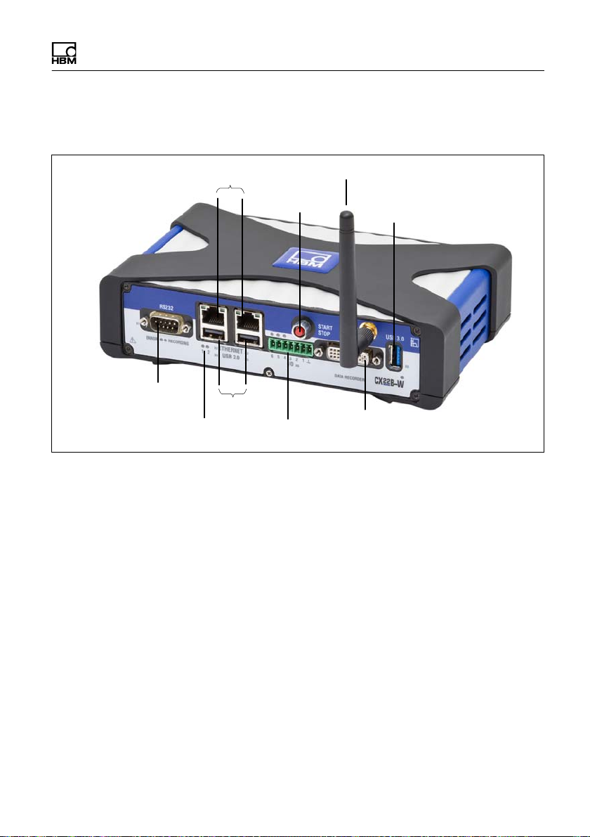
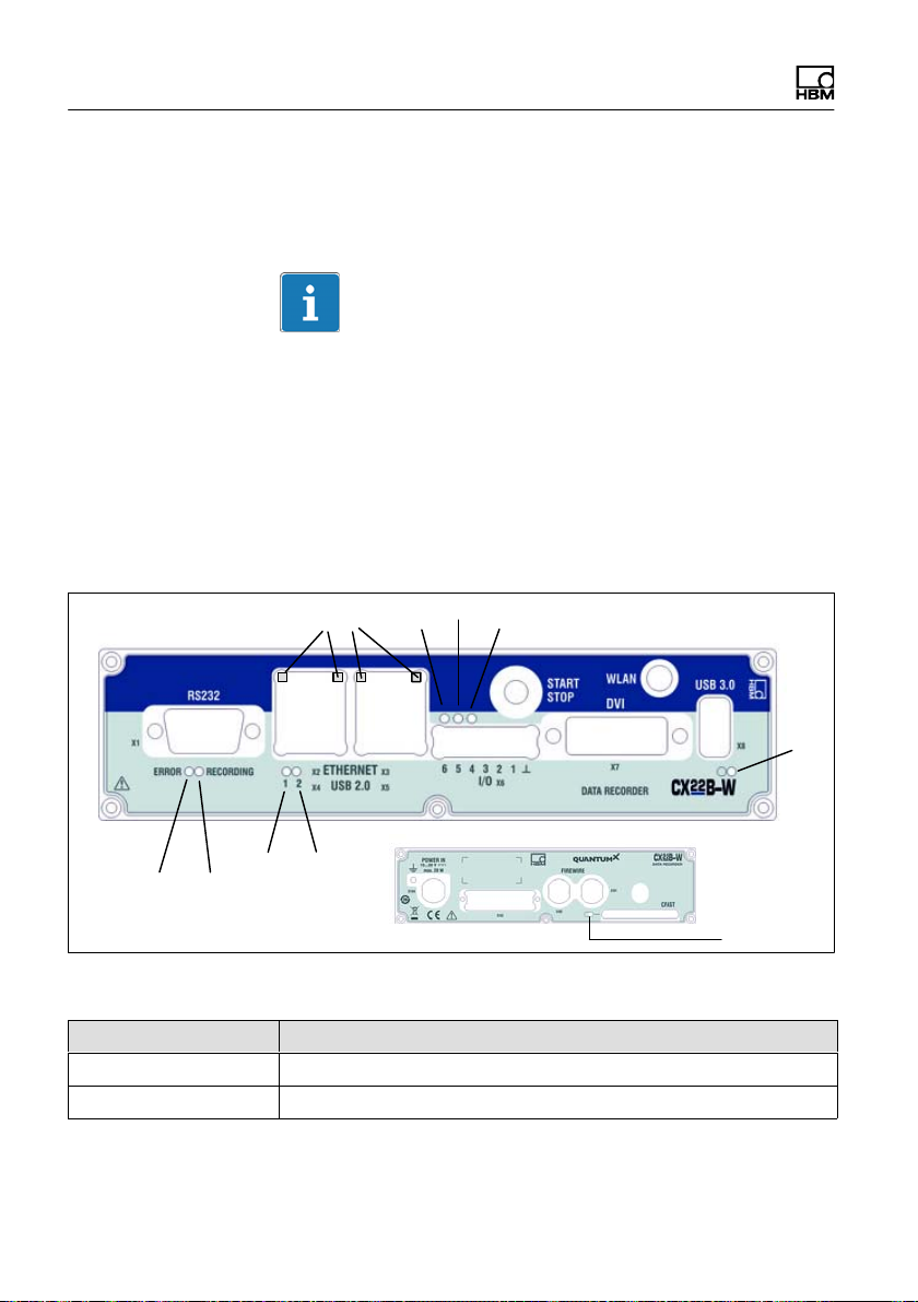
4 Connections and displays
Connections and displays
RS‐232‐C
Ethernet
Status LEDs
START/STOP
USB
Digital I/Os
WLAN antenna
button
USB 3.0
Monitor (DVI-D)
Fig. 4.1 CX22B‒W connections on the front
CX22B / CX22B-W A3169-8.0 HBM: public 15
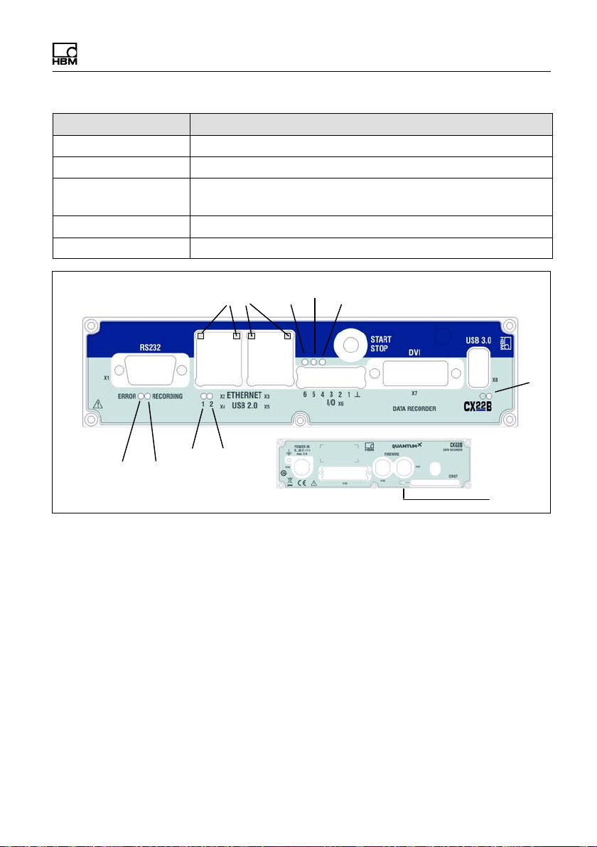
Page 18
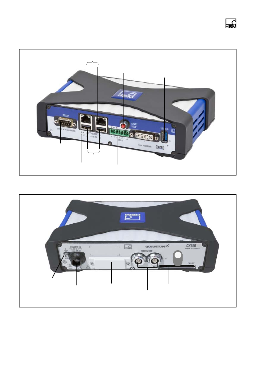
Connections and displays
Ethernet
RS‐232‐C
USB
Status LEDs
START/STOP button
Monitor (DVI-D)
Digital I/Os
USB 3.0
Fig. 4.2 CX22B connections on the front
Grounding
Supply voltage
DC 10 30V
Backplane con
nector strip
FireWire
CFast
Fig. 4.3 Connections on the back for CX22 and CX22B‒W
16 A3169-8.0 HBM: public CX22B / CX22B-W
Page 19

Connections and displays
4.1 Voltage supply
Apply a supply voltage of DC 10 - 30 V to connector
X104 (see Fig. 5.1). Use a voltage supply with sufficient
power, in case the QuantumX modules connected to the
CX22B‒W or devices such as GPS sensors, cameras or
data memory directly connected to the unit also need to
be supplied with power.
The DC voltage supply must be a SELV voltage supply,
meeting the requirements of IEC / EN / DIN EN 609501.
The supply voltage must be protected by an adequate
DC fuse (e.g. LITTELFUSE KLKD 6, LFPHV001) with a
maximum current of 5 A.
Notice
When modules are installed in a vehicle, we recommend
connection to a separate battery or integration of an unin
terruptible power supply (UPS), as battery voltage is par
ticularly likely to fall below 10 V when a combustion en
gine starts up, which would automatically cause the
modules to restart.
HBM offers the NTX001 power supply for laboratory or
general steady-state operation. On the primary side, this
provides a selection of international connector types and
24 V and 30 watts on the secondary side. A CX22B‒W
and one additional module can be supplied in this way.
See the respective module data sheets for precise details
of performance.
The Data Recorder can also be supplied with voltage by
a (FireWire) module group.
CX22B / CX22B-W A3169-8.0 HBM: public 17
Page 20

Connections and displays
The data recorder hosts a small buffer battery (type
CR2032, lithium). This battery keeps date and time
during power interruptions. The battery shall only be
replaced by HBM service.
4.2 Ground connection and grounding
Lay the signal and data leads separately from currentcarrying power lines. Cable ducts made of sheet metal
with an internal partition are ideal.
If there are differences in potential in or to the connected
measurement system, you must install a potential equal
ization line (recommended value: highly flexible stranded
wire, line cross-section 10mm2).
Important
4.3 Connection of QuantumX modules
The simplest way to connect measurement modules to
the CX22B‒W Data Recorder is via FireWire, or alterna
tively via Ethernet.
FireWire has the following advantages:
S Voltage supply, time synchronization, data communi
cation and real time in one cable and thus little effort
and low cost
S Every module has 2 FireWire connections, so flexible
topologies are possible: star, line or even hybrids with
an appropriate hub, also supplied with power via
FireWire.
Ethernet has the following advantages
18 A3169-8.0 HBM: public CX22B / CX22B-W
Page 21

Connections and displays
S The components used are readily available on the
market
S Up to 100 m line lengths to the module
S Synchronization via NTP or PTPv2 (IEEE1588:2008)
when using an appropriate switch
S Connection of modules via WLAN
4.4 Communication with the Data Recorder
You can work with the Data Recorder in the following
way:
S Directly connected peripherals
- Monitor or touchscreen (DVI, USB 3.0)
- Mouse and keyboard to USB
S Access via a PC or tablet by means of a "remote
desktop connection" (standard in Windows)
- Direct connection via an Ethernet patch cable
- Wireless connection (WLAN)
- In a network (LAN)
- Remote access via an Internet connection and a
mobile services provider using a mobile services
gateway
CX22B / CX22B-W A3169-8.0 HBM: public 19
Page 22

Connections and displays
4.5 Connector strip for backplane
The recorder can be integrated into the BPX001/002
backplane.
4.6 USB 2.0 and USB 3.0 interfaces
Devices such as a keyboard, mouse, monitor, printer, as
well as GPS sensors or data memory such as a USB
flash drive, can be connected.
Tips for use are available for the connection of GPS sen
sors via RS232 or USB.
Notice
If you have to install device drivers, please note Section
12.4.
integration
4.7 RS232 interface
An NMEA‐based GPS sensor can be connected via
RS232, for instance. The interface does not provide a
voltage supply. Other serial buses can be integrated to
the software on demand. A wide range of solutions is
already available.
20 A3169-8.0 HBM: public CX22B / CX22B-W
Page 23
Connections and displays
4.8 Digital inputs and outputs
Three inputs are available at terminals 1, 2 and 3 and
three outputs at terminals 4, 5 and 6. The status of the
outputs is indicated by LEDs, see Section 4.10.4.10.
Inputs
The level for the inputs is 5 volts in the open state
(HIGH), as it is pulled up to HIGH by a pull-up resistor
(active LOW). The maximum LOW level for the inputs is
0.7 volts.
Outputs
The level for the outputs is 5 volts (HIGH), when the cor
responding output is set, otherwise 0 volts (LOW). The
inputs and outputs are TTL-compatible, the line lengths
at the outputs must not exceed 3 m.
Tip
At the start of a DAQ job, outputs are reset to LOW if in
catman[EASY, in the options for the CX22B‒W (system
group), you activate the setting Reset all CX22B‒W
digital outputs at the start of a DAQ job.
4.9 START/STOP button
You can start and/or stop a DAQ job with the START/
STOP button. To do this, use a trigger for starting and/or
stopping the DAQ job and assign CX22B‒W digital in
put 3 - START/STOP button as the trigger channel.
CX22B / CX22B-W A3169-8.0 HBM: public 21
Page 24
Connections and displays
If you control the start and stop of the DAQ job via the
button, the DAQ job is started with the first press and
stopped with the next press of the button.
The START/STOP button is switched parallel to the input
on terminal 3. If you want to use the button, do not con
nect input 3. Otherwise the "Active" (LOW) state will be
triggered by pressing the button and by a LOW signal at
terminal 3.
4.10 LED displays
Important
3
5
6
4
7
2
1
10
9
8
Fig. 4.4 Position of the LEDs
LED Function
1, 2 Operating condition status
3 Ethernet status
22 A3169-8.0 HBM: public CX22B / CX22B-W
Page 25
Connections and displays
FunctionLED
4, 5, 6 Status of digital outputs
7 Module LED
8 Operating condition of the CFast memory card
(rear of module)
9 ERROR
10 RECORDING
5
3
2
9
1
10
6
4
7
8
Fig. 4.5 Position of the LEDs without WLAN
CX22B / CX22B-W A3169-8.0 HBM: public 23
Page 26
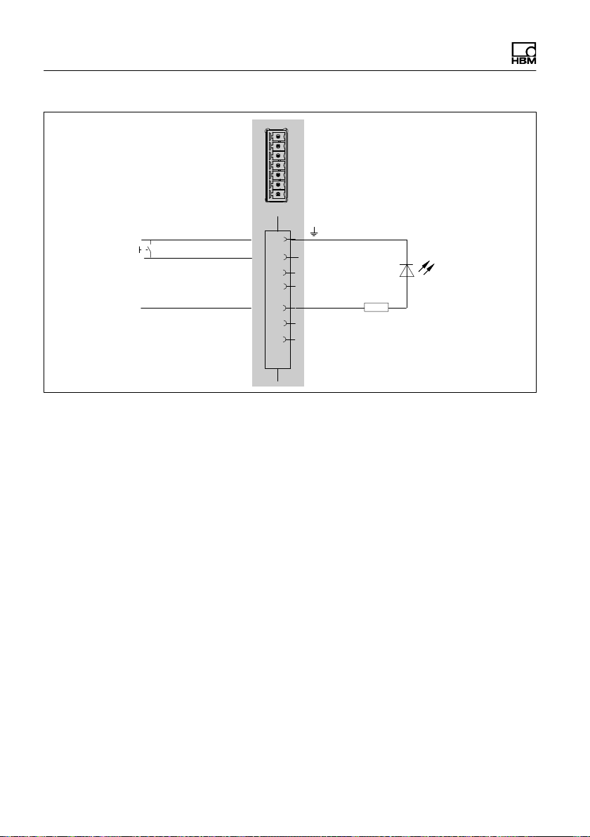
Connections and displays
Digital In‐/Outputs
Dig In 2 (same for 1 and 3)
>
1 mA
Fig. 4.6 Pin assignment digital In ‐ and Output
Dig Out 4 (same for 5 and 6)
IN
1
2
IN
3
IN
OUT
4
5
OUT
6
OUT
R
24 A3169-8.0 HBM: public CX22B / CX22B-W
Page 27

Connections and displays
Module LED
The module LED (see Fig. 4.1 on Page 15) lights up
green when the CX22B‒W power supply is present. The
module requires approx. 1 minute after switch-on before
the boot process is complete.
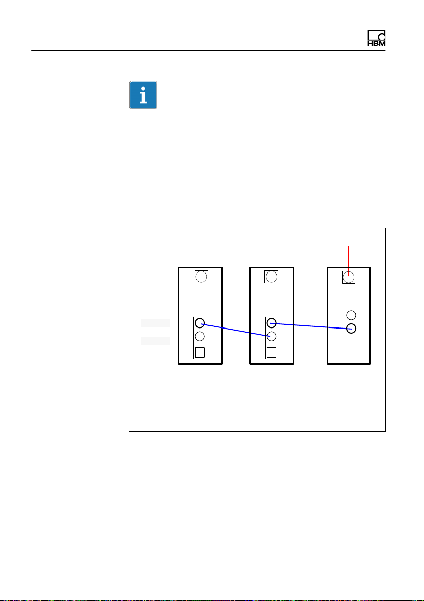
LEDs on the Ethernet connection
The LEDs light up as follows (see number 3 in Fig. 4.1):
The left LED lights up when an Ethernet connection is
present and flashes for a 10/100MBit network con
nection.
The right LED lights up when the device is working at
1GBit.
Status LEDs for the operating status
The "RECORDING" LED
shows continuously yellow when measurement data
are being recorded. If a start trigger was set, the LED
flashes yellow while waiting for the trigger event.
The "ERROR" LED
lights up yellow if the software detects an error, e.g.
when no connection could be set up to the devices at
the start of the project. The LED flashes if the avail
able free memory drops below 1 GByte.
All Status LEDs can also be triggered via Limit values
and events in catman EASY. To do this select Set dig
ital output: CX22B digital output in the Configure
limit value and event monitoring dialog and enter the
required LED in Bit/Condition.
CX22B / CX22B-W A3169-8.0 HBM: public 25
Page 28

Connections and displays
Status LEDs for digital outputs
The LEDs show the status of digital outputs 4 to 6. The
outputs are addressed via LEDs 4 to 6 in catmanEASY.
Set the outputs via limit value and event monitoring: En
ter 0 HIGH (LED 4) for Bit/Condition if output 4 is to be
active when the event occurs (LED 4 lights up green).
Outputs 5 and 6 are activated via bit 1 (LED 5) and bit 2
(LED 6).
The corresponding digital output is simultaneously
triggered in LEDs 4 to 6. The LEDs light up when the rel
evant output is set to HIGH.
LED for the operating condition of the CF card
The LED on the rear of the module flashes yellow when
data are written to or read from the CF card.
26 A3169-8.0 HBM: public CX22B / CX22B-W
Page 29

Connecting QuantumX modules
5 Connecting QuantumX modules
The simplest way to connect QuantumX modules to the
Data Recorder is via FireWire. Connect cable
1-KAB272-x to any of the Data Recorder's connections
and the other end to connection X102 of the nearest
measurement module.
Then keep threading: connection X102 to X101 of the
second measurement module, etc. Remember the maxi
mum current of 1.5 A. As a rule, you must introduce a
voltage supply again after 3 modules. You can also con
nect measurement modules at the other connection.
Alternatively, you can connect all the QuantumX modules
to the CX22B‒W via Ethernet. If you have more than two
modules, you will also require an Ethernet switch.
In the configuration shown below, the module supply volt
age is looped through via FireWire (max. 1.5 A via
FireWire). The power consumption of a module is ex
plained in the data sheet.
You can connect up to 12 modules to the CX22B‒W
Data Recorder via FireWire, with a supply feed required
for at least every 4th module, with approximately the
same voltage value. The general QuantumX operating
manual contains more detailed data on this.
CX22B / CX22B-W A3169-8.0 HBM: public 27
Page 30
Connecting QuantumX modules
Important
If you are already using QuantumX modules and want to
connect them to a CX22B‒W Data Recorder, please up
date the device firmware. CatmanEASY checks the
firmware automatically and if necessary, prompts you to
update the firmware. The relevant firmware package is
supplied with the Data Recorder and is located in the
sub-directory C:\Program Files
(x86)\HBM\catmanEasy_EN\Firmware\QuantumX-B\
X102
DC 10V ... 30V
X101
MX
FireWire connection
1-Kab272-x: connection cables of various lengths (x m)
Fig. 5.1 Connecting QuantumX modules to the Data
Recorder via FireWire
MX CX
28 A3169-8.0 HBM: public CX22B / CX22B-W
Page 31

X102
X101
Ethernet
Connecting QuantumX modules
DC 10V ... 30V
MX
DC 10V ... 30V
WLAN
Fig. 5.2 Connecting QuantumX modules to the Data
Recorder via Ethernet
MX
CX
CX22B / CX22B-W A3169-8.0 HBM: public 29
Page 32

Operating the Data Recorder
6 Operating the Data Recorder
6.1 Operation with monitor and keyboard/mouse
This type of operation is the simplest. It does not require
any configuration, but you will need a monitor with digital
input (DVI) and a mouse and keyboard with USB connec
tion.
Connect the mouse and keyboard to the USB sockets of
the CX22B‒W. The monitor is connected to the DVI
socket with a commercially available DVI monitor cable
(see Fig. 4.1 on Page 15 for all connections). Connection
via VGA is not possible, not even with a DVI/VGA
adapter plug, as the leads required for VGA are not as
signed.
Switch on the power supply and wait until the boot
process is complete and the module is ready.
Important
The CX22B‒W factory setting for input language (key
board layout) is EN (English). If you connect a keyboard
with a different layout, you should select Exit to Win
dows in the start screen and then press Shift and Alt, or
change the input language via the language bar in the
task bar.
If necessary, use the Windows control panel ("Regional
and Language Options") to set the Location) to your
country. The setting influences the digit settings and the
time, for example.
Make other settings via the Data Recorder start screen.
30 A3169-8.0 HBM: public CX22B / CX22B-W
Page 33

Operating the Data Recorder
Initial start-up
The pre-installed catmanEasy software can be updated
free of charge for 12 months from the date of delivery. To
run an update, you must first register with HBM, in order
to benefit from software maintenance. To do this, simply
send us the registration file created during initial start-up.
This contains the software license number and the
device serial number.
You can do this later at any time via the catman soft
ware.
6.2 Operation via a PC
In this case, the CX22B‒W Data Recorder is connected
to the PC via Ethernet. There are different variants, de
pending on your PC/network configuration, and the
procedure used to set up the connection depends on the
variant:
CX22B / CX22B-W A3169-8.0 HBM: public 31
Page 34

Operating the Data Recorder
S The CX22B‒W and PC are connected directly via an
Ethernet cable.
S The CX22B‒W Data Recorder is connected to an Eth
ernet network (the network configuration is usually
assigned automatically via DHCP, Dynamic Host Con
figuration Protocol).
For a detailed description, see Section 6.2.2, Page .
S The CX22B‒W Data Recorder is connected via
WLAN (ad‐hoc to a PC or hotspot integration into lo
cal area network-LAN).
Wait approx. 1 minute after switching on the CX22B‒W
before setting up a connection so that the boot process is
complete and the module is ready. Otherwise you may
receive an error message that the device could not be
found.
Important
To make it easier to set up a connection when the
CX22B‒W settings are unknown, use the HBM program
HBM Device Scan, which is part of the system software
and included in the package as a DVD. It is also available
to download from (www.hbm.com -> Support -> Down
loads).
You can also set up a direct remote desktop connection
(standard program of the Windows operating system).
You need to know the IP address of the device to do this.
The device is delivered with factory settings and DHCP.
So you must use the "HBM Device Scan" software for
the initial start-up at least, or work with the direct periph
erals.
32 A3169-8.0 HBM: public CX22B / CX22B-W
Page 35

Operating the Data Recorder
In Windows 7, for example, the remote desktop connec
tion program is found under:
All programs −> Accessories.
6.2.1 A direct Ethernet line between PC and Data Recorder
► Connect your PC and CX22B‒W via an Ethernet ca
ble, category CAT5e or higher.
► Install the HBM Device Manager program, which can
be found on the HBM support sites or in the software
package QuantumX / SomatXR system software.
► Launch the HBM Device Manager program on the PC:
Windows Start menu−> All programs−> HBM −>
HBM Device Manager.
► Click on Find devices.
► Select the Data Recorder from the list, the current
address(es) of the interface (WLAN only with
CX22B‒W) are also displayed. The module in Fig. 6.1
has the IP address 172.19.204.252.
CX22B / CX22B-W A3169-8.0 HBM: public 33
Page 36

Operating the Data Recorder
Fig. 6.1 Display of the found modules and whether
connection is possible
► The IP addresses and subnet masks of the interfaces
of your PC and the found modules are displayed In
the Settings section. Depending on the configuration
of your PC, you can configure the CX22B‒W end.
The simplest setting is DHCP/APIPA. Suitable IP ad
dresses are automatically organized between the two
devices and you can start work immediately.
► Alternatively, you can use permanent addresses for
both devices. In this case, you can change the
CX22B‒W address, for example. The latter is de
scribed below.
► Select the CX22B‒W from the list.
► In the TCP/IP settings for CX22B‒W field, click on
LAN and enter the required IP address and subnet
34 A3169-8.0 HBM: public CX22B / CX22B-W
Page 37

Operating the Data Recorder
mask. An address and subnet mask that lie within the
address range of your PC are automatically proposed,
you can however change this proposal. Enter an IP
address in which the first three digit groups match the
digit groups of the PC and only the last digit group
contains a different number between number from 1
to 254. The last digit group must not match the digit
group in the PC!
Example for IP address and subnet mask
IP address of the PC: 192.168.0.1/ subnet mask
255.255.255.0.
Possible combination:
IP address of the CX22B-W: 192.168.0.2 / sub
net mask 255.255.255.0
► Click on Apply and wait until the new address is
shown at the top. The symbol indicates that a con
nection is possible.
► Select the CX22B‒W once again in the list at the top
and then click on Remote connect.
► If Windows asks whether the connection should be
set up to this remote computer, set up the connection
(Fig. 6.2).We recommend activating the option Don't
ask me again for connections to this computer.
CX22B / CX22B-W A3169-8.0 HBM: public 35
Page 38

Operating the Data Recorder
Fig. 6.2 Windows-dialog: setting up the connection
► Depending on the configuration of your Windows
operating system, another query as to whether the
connection should be set up may be displayed (iden
tity of the remote computer, Fig. 6.3). If necessary,
activate the option to prevent the query.
36 A3169-8.0 HBM: public CX22B / CX22B-W
Page 39

Operating the Data Recorder
Fig. 6.3 Identity of the remote computer display
The connection to the CX22B‒W Data Recorder will now
be implemented and you must register with the device
(Windows login dialog).
CX22B / CX22B-W A3169-8.0 HBM: public 37
Page 40

Operating the Data Recorder
Fig. 6.4 Identity of the remote computer display
The following applies in the factory settings:
User name: HBMCX22
Password: hbm
Important
If you change the IP address and subnet mask, this is
not yet permanently saved. So in the start screen, click
on Commit changes and reboot or Save and restart, if
you have yet to change the language in the settings. This
will permanently save the new settings. The recorder will
then restart. You will have to set up the connection again
after the restart.
38 A3169-8.0 HBM: public CX22B / CX22B-W
Page 41

Operating the Data Recorder
6.2.2 Connection via a network
The settings for the CX22B‒W Data Recorder again de
pend on your network configuration. Please contact your
network administrator to obtain the correct settings.
► Install the "HBM Device Manager" program from the
system CD.
► Launch the program on your desktop or via the Win
dows Start menu −> All programs −> HBM −> HBM
Device Manager
► Click on Find modules.
► All the QuantumX and Somat modules, including the
Data Recorder, will appear in the list.
► The IP addresses and subnet masks of the PC inter
faces are displayed in the Settings of my computer
section on the left.
► In the TCP/IP settings for CX22B‒W section, click
on LAN and select DHCP off - normal in networks.
Please note the specifications of your network admin
istrator.
► Click on Apply and wait until the new setting is shown
at the top. The symbol should change to the
symbol and thereby indicate that a connection is
possible.
► Select the CX22B‒W once again in the list at the top
and then click on Remote connect.
For the next steps, please proceed as in the previous
Section.
CX22B / CX22B-W A3169-8.0 HBM: public 39
Page 42

Operating the Data Recorder
6.2.3 Connection via WLAN
The connection via WLAN can be implemented in two
different ways:
► You can set up a direct connection to the CX22B‒W
wirelessly from your PC or tablet. This type of connec
tion is known as an Adhoc network .
► You can integrate the CX22B‒W into an existing wire
less network. This requires a configured Access Point
and information regarding the network name, login
and password.
Setting up the CX22B‒W for Adhoc operation
► Make the following setting: Activate WLAN Adhoc
connection on startup
► Save the changes permanently (the Data Recorder is
rebooted after this action. The WLAN connection that
was previously set-up is lost).
► You can then remove the network cable and use your
PC to find the CX22B‒W wireless network and con
nect to it.
40 A3169-8.0 HBM: public CX22B / CX22B-W
Page 43

Operating the Data Recorder
► Now use the HBM Device Manager tool to set up an
Adhoc connection to the CX22B‒W.
Configuring the CX22B‒W for an Access Point
► To set up the wireless connection, you must first cre
ate access to the CX22B‒W. This is done convention
ally with a monitor and keyboard or remotely via the
LAN cable.
► Exit to Windows and click on the small pictogram at
the bottom right.
► Connect to the network and if necessary, enter the
network key. We recommend that you always work
with encryption (WPA2) and never use unsecured
networks.
► Save the changes permanently (the Data Recorder is
rebooted after this action. The WLAN connection that
was previously set-up is lost).
CX22B / CX22B-W A3169-8.0 HBM: public 41
Page 44

Operating the Data Recorder
If setting up the connection in the Adhoc network takes
too long, you can also assign permanent IP addresses
for the CX22B‒W and PC. The connection will then be
set up faster.
6.2.4 Connection via a tablet
Apple computers, smartphones or tablet PCs can also
set up a connection to the CX22B‒W. This is on condi
tion that a suitable program is installed on the particular
device. The screen resolution should be 1000 x 750
pixels, as otherwise only parts of the CX22B‒W Data
Recorder screen will be visible and you will have to keep
moving the pane.
For Intel‐based Macs, use the Microsoft
"Remote Desktop Connection Client" program (available
as a free download from the Microsoft website).
Tip
For other operating systems, there are numerous pro
grams for setting up a remote desktop connection to a
Windows PC, such as the Remote Desktop for Mobiles
RDM+ program for BlackBerry, Android or iPad.
42 A3169-8.0 HBM: public CX22B / CX22B-W
Page 45

Enter the IP address of
the CX22B‒W here
Operating the Data Recorder
6.3 Connection via remote desktop
If you do not want to use HBM's HBM Device Manager
program or are working with a permanent IP address at
the recorder end, you can also set up the connection di
rectly via the "remote desktop" program (the program is a
component of the Windows operating system). In Win
dows 7, the program can be found under
All programs −> Accessories.
Fig. 6.5 Enter the IP address of the QuantumX Data
Recorder
Procedure
► Enter the IP address of the CX22B‒W.
► Click on Connect.
Configuration of remote desktop
The HBM Device Manager program uses a minimal re
mote desktop configuration, that allows only the
CX22B‒W screen to be displayed on your PC. You can
fully configure a remote desktop connection, so that you
can also directly use your PC drives on the CX22B‒W,
CX22B / CX22B-W A3169-8.0 HBM: public 43
Page 46

Operating the Data Recorder
for example, or can use Ctrl-C (Copy) and Ctrl-V (Paste)
to exchange data between the PC and the CX22B‒W.
You can:
S Create your own definition for the remote desktop
connection. Launch the remote desktop connection
program. Enter the IP address of the CX22B‒W and
click on Options.
S Change the definition used by the HBM Device Man
ager program. To do this, open the CX22B.rdp file in
the installation directory of the HBM Device Manager
software.
The group policy of the network administrator can limit or
totally prevent changes being made to the settings for the
remote desktop connection. Contact your network
administrator if one of the settings mentioned below is
not available to you.
Important
Further procedure
► Go to the Local resources tab and activate Clip
board , for example, and/or Printers (Fig. 6.6).
This allows you to use the clipboard of your PC to copy
and paste data, as well to use your PC's printer from the
CX22B‒W.
44 A3169-8.0 HBM: public CX22B / CX22B-W
Page 47

Activate data exchange
via the clipboard
Operating the Data Recorder
Fig. 6.6 Remote desktop connection local resources tab
► Click on Next in the Local resources tab.
► Enable the required drives of your PC for use in the
CX22B‒W (Fig. 6.7).
CX22B / CX22B-W A3169-8.0 HBM: public 45
Page 48

Operating the Data Recorder
Enable drives for
use in the CX22B‒W
Fig. 6.7 Dialog for enabling additional resources
► Close the dialog.
► Save the configuration via the General tab either
under a new name (Save as) or as a default setting
for the connection via HBM Device Manager (Save),
see Fig. 6.8.
46 A3169-8.0 HBM: public CX22B / CX22B-W
Page 49

Domain and user
name (optional data)
Allow user name and
password to be
saved
Save settings
Operating the Data Recorder
Fig. 6.8 Saving the remote desktop configuration
If you double-click this configuration file (or a link to it), a
connection to the CX22B‒W is immediately set up, and
you only have to enter the password. If you authorize
Save credentials (see Fig. 6.8), this is done automati
cally.
CX22B / CX22B-W A3169-8.0 HBM: public 47
Page 50

Operating the Data Recorder
6.4 Detecting and resolving connection
If the CX22B‒W does not appear in the HBM Device
Manager list, or the setup of the remote desktop connec
tion is canceled, there are several possible causes.
Check the following points and then repeat the search:
S Has the CX22B‒W been switched on for at least 1
minute and is the module LED green.
S Is the Ethernet switch working properly?
If you cannot check functionality because you are not
operating any other devices on the switch, try to set
up a direct connection between the PC and the
CX22B‒W.
S Have you waited long enough for the PC to specify its
address?
If the PC cannot find a server in the network, the
search for the server looks in the "DHCP" settings
(Obtain an IP address automatically) and the "Alterna
tive configuration" (user-defined address) first of all
(the symbol for the interface in the Windows tray indi
cates the search, but the symbol may only appear if
the display is configured). It then takes about 20 to 30
seconds to set an automatic address (in DHCP) or the
stated alternative address. During this time, a scan
has not found a CX22B‒W either.
problems
S Could your firewall be responsible for blocking the
UDP scan?
Try deactivating your firewall or enable the following
TCP ports: 31416 & 31417
S Could your antivirus program be responsible for block
ing the UDP scan?
48 A3169-8.0 HBM: public CX22B / CX22B-W
Page 51

Operating the Data Recorder
Try deactivating your antivirus protection to locate the
cause. If the CX22B‒W can then be found, read your
antivirus program documentation to discover how to
enable individual programs to access the network
(local subnet). You must enable the same ports as
those described under the firewall.
S If a WLAN is also active in your PC, you must test
whether the module can be found when you
temporarily switch off the WLAN (just for the search
period). With some WLAN configurations, problems
can occur across all interfaces during a scan.
S If your PC has several Ethernet interfaces, try
deactivating all the other Ethernet interfaces.
S If the HBM Device Manager cannot find the
CX22B‒W, try setting up a "standard" remote desktop
connection.
S If you are using the CX22B‒W in a larger network,
contact your network administrator. There are a series
of options in managed networks to limit or completely
prevent data transmission between the individual
nodes. Administrative enabling may also be
necessary here.
6.5 Using Ethernet and WLAN in parallel
With the CX22B‒W Data Recorder, you can connect
modules via Ethernet and also connect your PC to the
CX22B‒W via Ethernet. But you can also connect the
modules via Ethernet and your PC to the CX22B‒W via
WLAN. The following combinations are possible, in addi
tion to connecting the modules via FireWire:
S Connect PC to CX22B‒W via Ethernet, connect
modules via the WLAN hub.
CX22B / CX22B-W A3169-8.0 HBM: public 49
Page 52

Operating the Data Recorder
S Connect PC to CX22B‒W via Ethernet, also connect
modules via Ethernet (switch or hub required).
S Connect PC to CX22B‒W via WLAN (Adhoc also pos
sible), connect modules via Ethernet (switch or hub
required).
S Integrate the CX22B‒W in the WLAN network, con
nect PC (and modules) via the (Ethernet) network.
50 A3169-8.0 HBM: public CX22B / CX22B-W
Page 53

The CX22B‒W Data Recorder start screen
7 The CX22B‒W Data Recorder start screen
Fig. 7.1 Start screen of the CX22B‒W Data Recorder
In the CX22B‒W start screen (CX22Shell), you can:
S Launch the catman EASY program.
S Change important CX22B‒W settings: Settings.
You can use this to change the device name (CX se
rial number) and the password, for example, as well
as the language of catman EASY. The Info tab con
tains information about the CX22B‒W hardware (ID),
the device serial number and the firmware version.
Also see Section12.2.
S Permanently store configuration changes: Commit
changes and reboot..
You must always click on this button if you have im
plemented any changes via the Settings button or in
CX22B / CX22B-W A3169-8.0 HBM: public 51
Page 54

The CX22B‒W Data Recorder start screen
the (Windows) system. This permanently stores the
changes that have been made.
S Terminate the remote desktop connection: Close re
mote connection.
You can also terminate the connection by closing the
remote desktop window.
S Switch to the system level (Windows): Exit to Win
dows.
This is necessary, for example, when you want to ac
tivate the CX22B‒W WLAN.
S Shut down the CX22B‒W Data Recorder: Shut
down.
This switches off the CX22B‒W. Interrupt the power
supply for approx. 5 seconds, to switch it back on
again.
S Call up the directory with the QuantumX system docu
mentation: Help.
S Call up the default directory with the measurement
data: Data.
This opens the directory specified in Settings on the
General tab.
Recalling the start screen
If you have used Exit to Windows to exit the start
screen, you can recall it via CX22Shell (on the Windows
desktop).
The link brings the start screen to the top.
52 A3169-8.0 HBM: public CX22B / CX22B-W
Page 55

The first DAQ job with catmanEASY
8 The first DAQ job with catmanEASY
Launch catmanEASY in the start screen.
► Run a device scan
► Select the required devices.
8.1 Creating a DAQ job
A DAQ project contains all the settings for the devices,
transducers (sensors) and calculations used, how the
measurement is to be carried out, and which data should
be visualized online and saved.
Setting up DAQ channels
If you are not using transducers with TEDS (Transducer
Electronic Data Sheet) assign the connected sensors
(transducers) to the channels: find your sensors in the
sensor list (Sensor database component window), then
drag&drop each sensor to the channel to which it is con
nected. Set up your sensors in the sensor database, as
required.
Assign unique channel names
You can generate channel names with sequential
numbering or accept the sensor designation via the Re
name context menu. In catmanEASY, each channel is
identified by its name, so you must use meaningful
names where possible.
► Mark the channels to be set to zero and run a zero
balance (zero balance, group zero balance).
CX22B / CX22B-W A3169-8.0 HBM: public 53
Page 56

The first DAQ job with catmanEASY
► Deactivate any unused channels
(group General, Active Deactivate channels without
sensors).
► Define calculations − if required − : Generate in the
group Calculation channels.
► Activate Live‐Display (DAQ channels , tab General
group), to display continuous measured values and
check that all channels are working correctly.
Set up the DAQ job
► Select your measurement conditions: data rate(s),
measurement start and stop.
► Select Measurement start via Trigger and Digital
input for Trigger mode, so that you can use the digi
tal inputs or the START/STOP button of the
CX22B‒W
Start Stop
Pre-Trigger Post-Trigger
Fig. 8.1 Starting and stopping measurement with a trigger.
All the measured values between start and stop, as
well as those in the pre-trigger and post-trigger
periods are recorded
► Click on Data storage (Settings group) and specify
the settings for saving the data after or during mea
surement. We recommend using the Automatically
at end of job setting for data storage. Otherwise a
monitor must be connected during measurement in
order to save the data.
► Generate visualization − if a monitor is connected.
54 A3169-8.0 HBM: public CX22B / CX22B-W
Page 57

The first DAQ job with catmanEASY
► Save your DAQ project: File menu −> Save −>
Project.
► Start your DAQ project via Start in the Measurement
group.
If you have not generated a visualization you will be
asked if one of the default settings for visualization
should be used.
► Click on Measure without display, if a monitor is not
connected during measurement.
CX22B‒W measurement mode is activated. If you have
defined a start trigger, e.g. The START/STOP button,
this will be waited for, if not, measurement will start. The
"RECORDING" LED flashes while waiting for the start
trigger and glows continuously as soon as measurement
starts.
Important
The "ERROR" LED lights up yellow if there is an error in
catmanEASY, e.g. if the connection to the devices at
project start cannot be set up or if the DAQ job cannot be
started. The "ERROR" LED flashes if the available free
memory drops below 1 GByte.
Tip
More information about catman[EASY can be found in
the catman[EASY online Help.
CX22B / CX22B-W A3169-8.0 HBM: public 55
Page 58

The first DAQ job with catmanEASY
General default settings, data storage and
directories
You should also consider whether additional directories
should be specified as default settings, and how to pro
ceed with the sensor database.
Procedure for directories
► In the catmanEASY start window, click on Addi
tional options.
► Use System −> Folders to specify the default
directories for your data and images. Set up additional
folders, e.g. "E:\Projects".
The settings are only used the first time the data or
images are saved, after this, catmanEASY always
retains the last folder used.
► If you want to carry out a great many calculations with
vast data sets, and a sizable CFast card has been
installed, also create the catman working directory on
drive E:, e. g. "E:\HBM\catWorkingDir".
Sensor database
The sensor database is an easy way to adjust the mea
suring chain to the sensor being used. You only need to
enter the characteristic values of a sensor once, after
which you can click to assign the sensor to the channel
to which it is connected. The device is then set to the
characteristic values of this transducer.
In the default setting (condition at the time of delivery) an
English sensor database is used once catman is
launched. But you can switch this to a German or French
language database. To do this, you first have to change
the language in the settings and then launch catman.
56 A3169-8.0 HBM: public CX22B / CX22B-W
Page 59

The first DAQ job with catmanEASY
The data are identical, it is just the sensor group names
that are in the respective languages.
Procedure for modifying the sensor database
► In catmanEASY, use the Sensor database context
tab and the File menu to load the relevant sensor
database from the installation directory "C:\Program
Files (x86)\HBM\catmanEasy_DE\" or "C:\Program
Files (x86)\HBM\catmanEasy_FR\".
► Save this sensor database under a different name to
drive D or E, and open it again. catman EASY will
automatically save the new path and file name and
use it the next time the program is launched.
If you want to keep the English version, merely save it
under a different name to drive D or E.
Use a different name if possible, as a sensor database
called HBM_SensorDatabase.sdb could be overwritten
when the system is updated (although you will be asked
whether this should happen). Import a new sensor
database to your sensor database to incorporate new
CX22B / CX22B-W A3169-8.0 HBM: public 57
Page 60

The first DAQ job with catmanEASY
sensors, as required. A description of this can be found
in the catmanEASY online help for the sensor data
base.
8.2 Transferring data/files to the PC
There are several ways for you to transfer the measure
ment data acquired by the CX22B‒W Data Recorder to
your PC:
1. Directly from CFast:
a.) CX22B switched off
Switch off the module, remove the CFast and plug the
card into your PC. Then copy the data from the card.
b.) CX22B during operation
Go to the Data Recorders start screen, push “Eject
memory card” and pull out the CFast card.
2. Via a USB flash drive, e.g. a USB memory stick:
Plug the USB flash drive into one of the CX22B‒W's
USB interfaces and connect the keyboard and moni
tor. In the start screen, click on Exit to Windows and
use the operating system (Windows Explorer) to copy
the files.
3. Data exchange via the clipboard:
Configure your remote desktop connection so that you
can exchange data via the clipboard, see Section on
Page.
4. Data exchange via a PC drive integrated into the
CX22B‒W as an external drive:
Configure your remote desktop connection so that
one or more of your PC's drives are integrated as
additional CX22B‒W drives, see Section 6.3.
58 A3169-8.0 HBM: public CX22B / CX22B-W
Page 61

The first DAQ job with catmanEASY
5. Via Windows Explorer:
Enter the IP address of the CX22B‒W in Windows
Explorer (Fig. 8.2, enter \\ in front of the address).
IP address entry
Fig. 8.2 Entering the IP address of the CX22B‒W in
Windows Explorer
In the logon dialog, enter the name of the CX22B‒W,
the user name and the password. In the factory set
tings, the device name is "CX serial number" and the
user name is HBMCX22. In this case, enter
HBMCX22 and the password hbm (Fig. 8.3).
CX22B / CX22B-W A3169-8.0 HBM: public 59
Page 62

The first DAQ job with catmanEASY
User name entry
Password entry
Fig. 8.3 Entering the device name, user name and password
The enabled CX22B‒W drives and directories are dis
played. In the factory settings, this is partition E:
enabled (enable name "E").
8.3 Data analysis
There are basically two ways to evaluate the measured
data:
S On the CX22B‒W (via remote desktop):
To do this, start an evaluation project in
catmanEASY or switch from measurement mode to
evaluation mode.
S On your PC:
To do this, you can use catmanEASY/AP, catman
Post Process or GlyphWorks from HBM, for example.
The recorded file formats can basically be converted
into any other format, such as MAT, ASCII and many
60 A3169-8.0 HBM: public CX22B / CX22B-W
Page 63

The first DAQ job with catmanEASY
others. If binary files (BIN) have been recorded, there
are also import filters for programs such as Glyph
Works, FAMOS and others.
8.4 Monitoring functionality
Since catman 5.0 a new module for monitoring applica
tions is introduced, which might be helpful as well for
other applications. The key features of this module are
explained below.
Important
All these functions are not included in catman Easy,
which comes with the CX22B. They need an additional
EasyMonitoring license or a catman®AP license.
- Parallel data recorders
A data recorder is similar to a DAQ job in that is has its
own start/stop conditions, storage file and other settings.
But while ordinary DAQ jobs can not run in parallel,
recorders can do this! A good example for the use of
recorders is the monitoring of a railway bridge, where
each of two tracks should be monitored separately.
A data recorder always belongs to a normal DAQ job.
This DAQ job is the "parent" or "base" job for the
recorders. Each base job can have a subset of up to 15
data recorders where each recorder runs a separate and
independent data storage process based upon individual
start/stop trigger conditions. It has its own set of
channels to be recorded and individual sample rates
including downsampling. Recordings can be repeated,
i.e. after one recording the recorder again starts waiting
CX22B / CX22B-W A3169-8.0 HBM: public 61
Page 64

The first DAQ job with catmanEASY
for a trigger. Each recorder generates its own data file
and also supports FTP upload.
If a base job containing recorders is launched (i.e. when
you click the green arrow symbol) the recorder objects
are created and put into "Waiting for start trigger" state.
To view the recorder statuses a separate window, called
the "Recorder console" will be shown.
- (S)FTP upload
Data files generated after a DAQ job can be automati
cally uploaded to an FTP server. SFTP with authentifica
tion and data encryption is supported. The FTP upload
runs asynchronously in the background so it does not
block further DAQ jobs. If a DAQ job contains video cap
ture the video files can also be uploaded. FTP configura
tion is part of the DAQ job settings, register tab "Remote
data storage".
- Push‐Notifications
Push notifications are short messages which can be
send via the HBM Push Server (a service offered by
HBM in the Internet) to any mobile smart device (e.g.
iPhone, Android based devices) worldwide. On the
mobile device you only need to install the HBM Push App
("HBM Push") which you can download from the App
Store (e.g. Google Play Store for android based devices
or Apple App Store for iPhone or iPad). Push notifica
tions are especially useful in unattended monitoring appli
cations, e.g. to observe signals crossing a certain level.
catman can send push notifications either event driven
(see Event monitoring) or via EasyScript. The message
may contain placeholders (e.g. a measurement value or
the name of the channel triggering the event). For more
information about this module, please see the knowledge
base of catman.
62 A3169-8.0 HBM: public CX22B / CX22B-W
Page 65

Configuring the CX22B‒W for self-contained measurements
9 Configuring the CX22B‒W for self-contained
measurements
Catman can be launched via the start screen (Settings
button).
Fig. 9.1 CX22 catman start‐up settings
CX22B / CX22B-W A3169-8.0 HBM: public 63
Page 66

Configuring the CX22B‒W for self-contained measurements
Settings must be made in two areas to configure the
CX22B‒W for self-contained measurement:
S You must make the applicable settings in DAQ jobs
and options in catmanEASY so that catmanEASY
loads a DAQ project and launches the DAQ job after
startup.
S You must ensure that catmanEASY starts when the
CX22B‒W is switched on.
As usual, measurement can be started and stopped
immediately, or via a trigger. But you can also use the
START/STOP button of the CX22B‒W, see Section 4.9
on Page 21.
Procedure
► Configure your DAQ project as described in Section
8.1. Set up the DAQ jobs so that the data are saved
with the Automatically on DAQ termination setting
(Data saving in the Settings group, Data storage
parameter).
► Save the DAQ project.
► Call up the catmanEASY options (file menu) and go
to Program start (System group).
► For Start mode, select an Existing DAQ project and
choose the project created above in the DAQ project
line.
► Activate the option Execute first DAQ job automati
cally.
► Go to DAQ channels in the Channels and sensors
group.
► Activate the option Automatically deactivate faulty
channels and continue measurement (behavior if
channel initialization fails).
64 A3169-8.0 HBM: public CX22B / CX22B-W
Page 67

Configuring the CX22B‒W for self-contained measurements
► Exit the dialog by clicking on OK.
► Exit catmanEASY.
► In the start screen, click on Settings.
► On the General tab, activate the option Launch DAQ
software (catmanEASY) at CX22B‒W startup and
click on OK.
► Click on Commit changes and reboot to perma
nently save the new settings.
This project will then start automatically the next time the
CX22B‒W is switched on. If the power supply is inter
rupted during measurement, the project will be reloaded
and measurement continued when the power supply is
restored. The module restart, up to the continuation of
measurement, will require approx. 3 minutes, depending
on the number of connected devices and channels.
Important
The data already present in the catman[EASY tempo
rary measurement data memory are not lost if the power
supply is interrupted. Any additional files will be assigned
a counter at the end of the file name.
CX22B / CX22B-W A3169-8.0 HBM: public 65
Page 68

Saving data on the Data Recorder
10 Saving data on the Data Recorder
10.1 Memory partitioning
The available memory in the CX22B‒W Data Recorder
allocated as follows:
S 16 GByte are used for the operating system and are
specifically protected against (unintentional) change
(partition C, EWF filter).
S 48 GByte are readily available for the application and,
optionally, for measured data (partition D).
C:\ Windows 8
Embedded
including
catmanEASY
16 GB
Internal SSD Internal SSD
D:\ Application and
measurered data
48 GB
Fig. 10.1 Partitioning of the available memory
E:\ Measurement
Removable CFast card (in
scope of supply 8 Gbyte)
data
Important
All changes made in partition C: are only temporary, as
this partition is protected against change (EWF,
see Section 10.4). In the start screen, click on Commit
changes and reboot, to permanently save the new set
tings or the newly installed software. The CX22B‒W is
then rebooted, so you must set up the connection again
after the restart.
66 A3169-8.0 HBM: public CX22B / CX22B-W
Page 69

Saving data on the Data Recorder
Important
Only ever save the measurement data to the internal
SSD (partition D), the removable CFast card or to mem
ory connected via USB. Data storage to the removable
CFast card and checking the quality of the storage
medium at regular intervals is recommended.
Important
CFast cards only have a limited number of write cycles,
i.e., they age (typically 1,000,000 write
cycles). You should therefore check the CF card regu
larly for errors in Windows and replace with a new card
where necessary. The life of a CF card depends on the
demands made on it, and the manufacturer.
Make sure that you use an up-to-date, high-quality
CFast, in order to achieve a high data transfer rate.
The scope of supply for the CX22B‒W Data Recorder
includes an 8GByte CF card, although cards with a
higher memory capacity can also be used (for example
64, 128, 256 or 512 GB).
CX22B / CX22B-W A3169-8.0 HBM: public 67
Page 70

Saving data on the Data Recorder
10.2 Removing and inserting the CFast
memory card
Notice
Do not replace the CFast when data are being written to
it. If this is combined with a sudden loss of power, the
memory card or the device could be damaged, or − if
measurement data are being recorded − all the data of
the test could be lost. When operation is ongoing, the
memory card can be disabled under Windows. It is best
to switch off the CX22B‒W before replacing the CFast.
► Undo the retaining screw for the CFast. The screw
must not be removed, it should just be loosened.
► Swivel the cover plate upwards to expose the slot for
the CFast.
► Press on the memory card with your finger to remove
it.
► Hold the CFast with the top facing upwards and slide
it into the slot until the memory card engages. The
CFast must disappear completely inside the slot.
► Swivel the cover plate downwards and secure the
card.
► Tighten the retaining screw by hand.
68 A3169-8.0 HBM: public CX22B / CX22B-W
Page 71

Saving data on the Data Recorder
Important
In the factory settings, the measurement data on the
removable CFast medium is written to Drive\Data and
enabled in the network as "External CFast data". Some
catman
[
EASY default directories are also set to this
directory.
So also create the directory on the new CFast. Enabling
is not necessary for working with catman[EASY .
10.3 Memory performance
Maximum cumulative recording rate
(data storage)
Internal memory SSD
With (temporary) dynamic measurement
data memory (BIN)
1)
With (temporary) static measurement data
memory (BIN)
In FastStream mode2
2)
2)
For the installed CFast
With (temporary) dynamic measurement
data memory (BIN)
1)
With (temporary) static measurement data
memory (BIN)
In FastStream mode
1)
Test conditions: 14 modules (FireWire), 56 DAQ channels, 8 bytes per measured value, 2 data
rate groups, no visualization objects
2)
Test conditions: 14 modules (FireWire), 56 DAQ channels, 8 bytes per measured value, 1data
rate group, no visualization objects
2)
2)
MS/s
MS/s
MS/s
MS/s
MS/s
MS/s
4
> 5
> 5
3
> 5
> 5
CX22B / CX22B-W A3169-8.0 HBM: public 69
Page 72

Saving data on the Data Recorder
As a rough guideline, data throughput should be calcu
lated in MByte/s. A signal (sample) can be calculated
with 8 bytes. The opportunity is also available to experi
mentally check whether the chosen configuration works.
Diagnostic options are available via the lower status bar
in catman, to gain an overview of processor and memory
utilization at the start of acquisition.
10.4 EWF, safeguarding your settings
against change
The program called EWF (Enhanced Write Filter) pre
vents the files on partition C: being (unintentionally)
changed or overwritten. This could happen, for example,
if the voltage supply fails and Windows is not properly
shut down. In this situation, the program always restores
the "previous" state when the CX22B‒W is next switched
on.
All the data or programs saved on C: are therefore only
stored temporarily, and are deleted again once the sys
tem is switched back on.
If you want to permanently save settings or programs on
C:, you must use Commit changes and reboot in the
start screen ("CX22Shell"). Changes will then be perma
nently applied and will also be available the next time you
restart the CX22B‒W.
70 A3169-8.0 HBM: public CX22B / CX22B-W
Page 73

Operating the CX22B/CX22B-W as gateway
11 Operating the CX22B/CX22B-W as gateway
11.1 Description
The gateway mode allows to route QuantumX modules
that are connected via firewire to other network adapters
of the CX22B-W (e.g. ethernet or WLAN). In this mode,
the data recorder acts like any other gateway module
such as the CX27B, however, with higher data through
put.
Important
When the CX22B-W is in gateway mode, it cannot be
used as a recorder. This means that catman shall not run
on the recorder while the CX22B-W is configured in gate
way mode.
11.2 Activate/deactivate gateway mode
To activate/deactivate the gateway mode, go in the Shell
settings of the CX22B-W into the "General" tab. Check
the option "Activate gateway functionality" to activate the
option and uncheck it to deactivate it.
CX22B / CX22B-W A3169-8.0 HBM: public 71
Page 74

Operating the CX22B/CX22B-W as gateway
Notice
The CX22B-W will have to reboot to activate/deactivate
the gateway mode.
11.3 Connect to a QuantumX module
behind a CX22B-W
To connect to a QuantumX module being routed by a
CX22B-W, start catman on your PC and search for mod
ules in the device manager..The modules routed by the
CX22B-W are displayed as child elements of the
CX22B-W. Unlike the CX27B Ethernet / EtherCAT gate
way, you can select QuantumX modules individually.
72 A3169-8.0 HBM: public CX22B / CX22B-W
Page 75

Operating the CX22B/CX22B-W as gateway
Important note: You can connect only time simultane
ously to a QuantumX module being routed by the
CX22B-W.
CX22B / CX22B-W A3169-8.0 HBM: public 73
Page 76

Operating the CX22B/CX22B-W as gateway
11.4 Performances
The CX22B-W can route up to 3MS/s.
The following table shows the different tests we made to
benchmark the performances of the gateway mode in the
CX22B-W:
Maximum cumulative data througput (gateway mode)
LAN (Gigabit)
WLAN interface (adhoc)
1)
Test conditions: 12 modules (FireWire), 48 DAQ channels
2)
Test conditions: 14 modules (FireWire), 108 DAQ channels
1)
2)
MS/s
MS/s
> 3
> 0.2
74 A3169-8.0 HBM: public CX22B / CX22B-W
Page 77

System settings, update and recovery
12 System settings, update and recovery
12.1 Installing drivers
Drivers, for USB peripherals, for example, can be
installed at any time. Although the installation of other
software packages is also possible in principle, we do not
recommend this on a large scale, in order not to endan
ger the stability of the CX22B‒W Data Recorder. If addi
tional software is installed, the functionality of the
CX22B‒W Data Recorder can no longer be guaranteed
and HBM can no longer provide support for any faults
arising in this connection.
In practice, drivers have already been successfully
installed and operated for the following terminal equip
ment: touchscreen (plus touch keyboard), camera (e.g.
Logitech), GPS (Navilock), FTP service (TurboFTP with
AutoStart and transfer of DAQ files to a central cloud
server, Winscp, GoodSync, allwaysync, watchDirectory
Professional).
Important
Changes to the system must be permanently saved
before restarting. To do this, click on Commit changes
and reboot in the start screen.
Also see EWF, Chapter 10.4 on Page 70.
CX22B / CX22B-W A3169-8.0 HBM: public 75
Page 78

System settings, update and recovery
12.2 Changing system settings (Settings)
Important
All changes in the Settings dialog are only permanently
saved and active the next time you switch on if you click
on Commit changes and reboot in the start screen
after making any changes.
In the start screen, click on Settings and go to the
appropriate tab to change the settings.
The following settings can be changed:
S Computer name (CX serial number, General tab)
This name is displayed in the network, for example.
S Password (Remote access password tab)
The password is required to log In.
S Run catmanEASY after switching on the CX22B‒W
(launch catman after CX22 startup, General tab)
76 A3169-8.0 HBM: public CX22B / CX22B-W
Page 79

System settings, update and recovery
Automatically starts catmanEASY as soon as the
system is operational. Also see Chapter 9 on
Page 63.
S Waiting time: period before catman starts up
S The language version of catmanEASY (language of
the DAQ software, the operating system and key
board input, General tab)
Select EN for the English interface, DE for the Ger
man interface and FR for the French version of cat
manEASY.
S Data directory: enter the storage location. This direc
tory is opened when you click on the "Data"
button on the start screen.
S Activate WiFi Adhoc connection at startup: activates
an Adhoc profile, so that a direct WLAN connection
can be set up to the CX22B.
Important
Store the password safely after changing it. If you lose it
you will need to restore the system to obtain access to
the CX22B‒W again.
The Info tab contains information about the CX22B hard
ware (ID), the device serial number and the firmware ver
sion.
12.3 Updating the software
You can update catmanEASY only, or enable additional
function packages such as EasyVideo, EasyRoadLoad
and EasyScript or a full catmanAP at any time, if you
CX22B / CX22B-W A3169-8.0 HBM: public 77
Page 80

System settings, update and recovery
have the relevant license key available. Please install the
software from a USB flash drive or from a network drive.
You can also update the MX Assistant software at any
time.
12.4 System restoration (Recovery)
If the changes you have made to the system result in the
system becoming inoperable, you can restore the deliv
ery condition of the system. Neither the data saved on
the removable CFast nor partition D: of the internal mem
ory with catmanEASY defaults will be overwritten during
recovery. To restore the system, you will need a specially
prepared bootable USB flash drive, a keyboard and,
where possible, a (digital) monitor that you can connect
directly to the CX22B‒W (DVI output). Please contact
our support site (http://www.hbm.com/support).
12.5 Potential sources of error and
remedial action
Long Ethernet cables
There are certain cases when there might be problem
setting up a connection with the installed Intel i210
Ethernet controller. The controller generates a link pulse,
which is required to set up the connection, but not com
pliant with the Ethernet specification. If you experience
problems, the network search (scan) will not function.
78 A3169-8.0 HBM: public CX22B / CX22B-W
Page 81

System settings, update and recovery
Sensor failure or removing a sensor during
measuring mode
You have the option to configure catman so that the sig
nal value assumes the value you have preset and an
entry is written in the logbook.
Module decoupled
A module or an entire module string may become
detached, particularly in the distributed module group,
e.g. in trains. You have the option to configure catman so
that measurement continues or is canceled.
CX22B / CX22B-W A3169-8.0 HBM: public 79
Page 82

FCC (USA) and CI (Canada) statement
13 FCC (USA) and CI (Canada) statement
Important
This equipment has been tested and complies with
the limits for a Class A digital device, pursuant to
part 15 of the FCC and CAN ICES-3 (A)/NMB-3(A)
rules. These limits are designed to provide reaso
nable protection against harmful interference when
the equipment is operated in a commercial environ
ment. This equipment generates, uses, and can
radiate radio frequency energy and, if not installed
and used in accordance with the instruction
manual, may cause harmful interference to radio
communications. Operation of this equipment in a
residential area is likely to cause harmful interfe
rence in which case the user will be required to cor
rect the interference at his or her own expense.
Additionally, this digital device need to be used
exclusively as industrial or commercial test equip
ment and is exempted from FCC respectively ICES
rules, pursuant to part 15, §103 of the FCC rules
and ICES-003, chapter 4. Connection of equip
ment, changes or modifications not expressly aut
horized by HBM (e.g. by this product manual) may
cause additional interference and could void the
users authority to operate the CX22B.
The data recorder CX22B-W comes along with the
integrated wireless LAN module WLE200NX from
Compex supporting the IEEE-Standards
802.11a/b/g/n. This module conforms to CE, FCC
80 A3169-8.0 HBM: public CX22B / CX22B-W
Page 83

FCC (USA) and CI (Canada) statement
and IC standards.
FCC number: TK4-10-WLE200NX
IC number: 7849A-WLE200NX
The wireless module has been tested and verified
that it covers the regulations according to part 15C
and 15E of the FCC standard and the Canadian
regulations RSS-210. These regulations guarantee
adequate protection against interference and noise
in commercial and industrial areas. This device
generates and uses energy in the radio frequency
range and can radiate those, if not used in other
ways than described in this documentation can
cause harmful interferences for communication.
Operation of this device in residential areas can
cause harmful interferences. In this case the user is
obliged clearing off the radio transmission interfe
rence at own cost.
The European conformity declaration is available
on our HBM webpage:
www.hbm.com
→ Instruments → Universal Data
Recorders → Downloads
Every connection of equipment, changes or modifi
cations not expressly authorized by HBM may
cause additional interference and could void the
user’s authority to operate the CX22B-W. This is
particularly applicable when replacing the antenna.
The wireless LAN module is in accordance with the
regulations of FCC in non-controlled environment.
During operation the minimum distance between
device and persons shall be 20 cm (~ 8 inches).
CX22B / CX22B-W A3169-8.0 HBM: public 81
Page 84

Waste disposal and environmental protection
14 Waste disposal and environmental protection
All electrical and electronic products must be disposed of
as hazardous waste. The correct disposal of old equip
ment prevents ecological damage and health hazards.
Statutory waste disposal mark
The electrical and electronic devices that bear this sym
bol are subject to the European waste electrical and elec
tronic equipment directive 2002/96/EC. The symbol indi
cates that, in accordance with national and local
environmental protection and material recovery and recy
cling regulations, old devices that can no longer be used
must be disposed of separately and not with normal
household garbage.
As waste disposal regulations may differ from country to
country, we ask that you contact your supplier to
determine what type of disposal or recycling is legally
applicable in your country.
Packaging
The original packaging of HBM devices is made from
recyclable material and can be sent for recycling. For
ecological reasons, empty packaging should not be
returned to us.
82 A3169-8.0 HBM: public CX22B / CX22B-W
Page 85

15 Index
Index
A
Ambient conditions, 5
Android, connected with CX22, 42
Apple, connected with CX22, 42
Self-contained measurement, 64
B
Button for START/STOP, 21
C
catman AP
change language, 77
start, 51
startup, 76
CF card
LED, 26
removing, 68
Cleaning, 6
D
Device name change, 51
DHCP, 32
Digital inputs, 21
Digital output reset, 21
Digital outputs, 21, 26
E
ERROR (LED), 25
EWF, 70
I
Input language, 30
K
Keyboard, 30
Keyboard layout, 30
CompactFlash card, 66
Connections, 15, 27, 30
CX22
shut down, 52
start screen, 51
CX22 Start screen, 51
CX22B / CX22B-W A3169-8.0 HBM: public 83
L
Language
changed from catmanAP, 77
von catmanAP ändern, 51
Log On change, 51, 76
Page 86

Index
M
Maintenance, 6
Markings, 10
Module LED, 25
Monitor
DVI, digital, 30
VGA, 30
O
Output reset, 21
P
Password change, 51, 76
PC, connection via WLAN, 43
Protective conductor, 11
R
Settings, 76
Stand-alone mode, 64
Start screen, siehe CX22 Start
Screen, 51
START/STOP button, 21
Status LED
operating status, 25
digital outputs, 26
Switching off the CX22, 52
Symbols on the module, 11
System restoration, 78
System settings, changing, 76
T
Tablet PC, connected with CX22,
42
RECORDING (LED), 25
Recovery, 78
CX22-System, 78
Remote desktop, close, 52
Remote Desktop for Mobiles, 42
S
Sensor database, 56
84 A3169-8.0 HBM: public CX22B / CX22B-W
Page 87

Operating Manual | Bedienungsanleitung
English Deutsch
CX22B / CX22B-W
Datenrekorder
Page 88

Deutsch
1 Sicherheitshinweise 4......................................
2 Verwendete Kennzeichnungen 10.............................
2.1 In dieser Kurzanleitung verwendete Kennzeichnungen 10..........
2.2 Auf dem Modul angebrachte Symbole und ihre Bedeutung 11.......
3 Einleitung 13................................................
4 Anschlüsse und Anzeigen 16.................................
4.1 Spannungsversorgung 18......................................
4.2 Masseverbindung und Erdung 19...............................
4.3 Anbindung von QuantumX‐Modulen 19..........................
4.4 Kommunikation mit dem Datenrekorder 20.......................
4.5 Steckleiste zur Integration in den Modulträger 21..................
4.6 Schnittstellen USB 2.0 und USB 3.0 21..........................
4.7 Schnittstelle RS232 21........................................
4.8 Digitale Ein‐ und Ausgänge 22..................................
4.9 START/STOP‐Taste 22.......................................
4.10 LED‐Anzeigen 23.............................................
5 Anschließen von QuantumX‐Modulen 28......................
6 Bedienen des Datenrekorders 31.............................
6.1 Bedienen mit Bildschirm und Tastatur/Maus 31...................
6.2 Bedienen über einen PC 33....................................
6.2.1 Direkte Ethernetleitung zwischen PC und Datenrekorder 34........
6.2.2 Verbindung über ein Netzwerk 40...............................
6.2.3 Verbindung über WLAN 41.....................................
6.2.4 Verbindung über ein Tablet 43..................................
6.3 Verbindung über Remotedesktop 45.............................
6.4 Verbindungsprobleme erkennen und lösen 50....................
6.5 Ethernet und WLAN parallel nutzen 52...........................
2 A3169-8.0 HBM: public CX22B / CX22B-W
Page 89

7 Der Startbildschirm des CX22B‒W‐Datenrekorders 53..........
8 Der erste Messjob mit catman[EASY 56......................
8.1 Erstellen eines Messjobs 56....................................
8.2 Übertragen von Daten/Dateien zum PC 61.......................
8.3 Auswerten von Daten 64.......................................
8.4 Monitoring‐Funktion 65........................................
9 CX22B‒W für autarke Messungen konfigurieren 68............
10 Daten speichern auf dem Datenrekorder 71....................
10.1 Aufteilung des Speichers 71....................................
10.2 Entfernen und Einsetzen der CFast‐Speicherkarte 73..............
10.3 Speicherperformance 74.......................................
10.4 EWF, die Sicherung gegen Einstellungsänderungen 75............
12 Systemeinstellungen, Update und Wiederherstellen 80.........
12.1 Installieren von Treibern 80....................................
12.2 Systemeinstellungen ändern (Einstellungen) 81...................
12.3 Software aktualisieren 83......................................
12.4 System wiederherstellen (Recovery) 83..........................
12.5 Mögliche Fehlerquellen und Abhilfe 84...........................
13 Erklärung zur FCC (USA) und CI (Canada) Konformität 85......
14 Entsorgung und Umweltschutz 88............................
15 Stichwortverzeichnis 89......................................
CX22B / CX22B-W A3169-8.0 HBM: public 3
Page 90

Sicherheitshinweise
1 Sicherheitshinweise
Bestimmungsgemäße Verwendung
Der QuantumX‐Datenrekorder darf ausschließlich für
Messaufgaben und direkt damit verbundene Steuerungs
aufgaben im Rahmen der durch die technischen Daten
spezifizierten Einsatzgrenzen verwendet werden. Jeder
darüber hinausgehende Gebrauch gilt als nicht bestim
mungsgemäß.
Zur Gewährleistung eines sicheren Betriebes darf das
Modul nur nach den Angaben in den Bedienungsanleitun
gen betrieben werden. Bei der Verwendung sind zusätz
lich die für den jeweiligen Anwendungsfall erforderlichen
Rechts‐ und Sicherheitsvorschriften zu beachten. Sinn
gemäß gilt dies auch bei der Verwendung von Zubehör.
Vor jeder Inbetriebnahme des Moduls ist eine Projektie
rung und Risikoanalyse vorzunehmen, die alle Sicher
heitsaspekte der Mess‐ und Automatisierungstechnik
berücksichtigt. Insbesonders betrifft dies den Personen‐
und Anlagenschutz.
Bei Anlagen, die aufgrund einer Fehlfunktion größere
Schäden, Datenverlust oder sogar Personenschäden
verursachen können, müssen zusätzliche Sicherheitsvor
kehrungen getroffen werden. Im Fehlerfall stellen diese
Vorkehrungen einen sicheren Betriebszustand her.
Dies kann z.B. durch mechanische Verriegelungen, Feh
lersignalisierung usw. erfolgen.
4 A3169-8.0 HBM: public CX22B / CX22B-W
Page 91

Sicherheitshinweise
Hinweis
Ein Modul darf nicht unmittelbar ans Stromversorgungs
netz angeschlossen werden. Die Versorgungsspannung
darf DC 10 V ... 30 V betragen.
Bei im Fahrzeug verbauten Modulen empfehlen wir den
Anschluss an eine separate Batterie oder die Integration
einer Unterbrechungsfreien Stromversorgung (USV), da
vor allem beim Start eines Verbrennungsmotors die
Batteriespannung unter 10 V fallen kann und damit die
Module automatisch einen Neustart ausführen.
Allgemeine Gefahren bei Nichtbeachten der
Sicherheitshinweise
Der QuantumX‐Datenrekorder entspricht dem Stand der
Technik und ist betriebssicher. Von dem Modul können
Restgefahren ausgehen, wenn es von ungeschultem
Personal unsachgemäß eingesetzt und bedient wird.
Jede Person, die mit Aufstellung, Inbetriebnahme,
Wartung oder Reparatur des Moduls beauftragt ist, muss
die Bedienungsanleitungen und insbesondere die sicher
heitstechnischen Hinweise gelesen und verstanden
haben.
Bedingungen am Aufstellungsort
S Schützen Sie das Modul vor direktem Kontakt mit
Wasser.
S Schützen Sie das Modul vor Schmutz und Feuchtig
keit oder Witterungseinflüssen wie beispielsweise
Regen, Schnee usw. Die Schutzklasse laut DIN
EN60529 beträgt IP20.
CX22B / CX22B-W A3169-8.0 HBM: public 5
Page 92

Sicherheitshinweise
S Beachten Sie die in den technischen Daten angege
benen maximal zulässigen Umgebungstemperaturen.
S Achten Sie darauf, dass die seitlichen Lüftungsöffnun
gen nicht zugedeckt sind.
S Die zulässige relative Luftfeuchte bei 31°C beträgt
80% (nicht kondensierend); lineare Reduzierung bis
50% bei 40°C.
S Schützen Sie das Modul vor direkter Sonneneinstrah
lung.
S Stellen Sie das Gerät so auf, dass eine Trennung
vom Netz jederzeit problemlos möglich ist.
S Das Modul kann bis zu einer Höhe von 2000 m sicher
betrieben werden.
Wartung und Reinigung
Die Module sind wartungsfrei.
S Trennen Sie vor der Reinigung die Verbindung zu
allen Anschlüssen.
S Reinigen Sie das Gehäuse mit einem weichen und
leicht angefeuchteten (nicht nassen!) Tuch. Verwen
den Sie auf keinen Fall Lösungsmittel, da diese die
Beschriftung oder das Gehäuse angreifen könnten.
S Achten Sie beim Reinigen darauf, dass keine Flüssig
keit in das Modul oder an die Anschlüsse gelangt.
Restgefahren
Der Leistungs‐ und Lieferumfang des QuantumX‐Sys
tems deckt nur einen Teilbereich der Messtechnik ab.
Sicherheitstechnische Belange der Messtechnik sind
zusätzlich vom Anlagenplaner/Ausrüster/Betreiber so zu
planen, zu realisieren und zu verantworten, dass Rest
6 A3169-8.0 HBM: public CX22B / CX22B-W
Page 93

Sicherheitshinweise
gefahren minimiert werden. Jeweils existierende Vor
schriften sind zu beachten.
Produkthaftung
In den folgenden Fällen kann die vorgesehene Sicherheit
des Gerätes beeinträchtigt sein. Die Haftung für die
Gerätefunktion geht dann auf den Betreiber über:
S Das Gerät wird nicht entsprechend der Bedienungs
anleitung benutzt.
S Das Gerät wird außerhalb des in diesem Kapitel
beschriebenen Anwendungsbereichs eingesetzt.
S Am Gerät werden vom Betreiber unautorisiert
Änderungen vorgenommen.
Sicherheitsbewussten Arbeiten
Ein Gerät darf nicht unmittelbar an das Stromversor
gungsnetz angeschlossen werden. Die Versorgungs
spannung darf DC 10 V ... 30 V betragen.
Der Versorgungsanschluss sowie alle anderen
Anschlüsse müssen so installiert werden, dass elektro
magnetische Einstreuungen keine Beeinträchtigung der
Gerätefunktionen hervorrufen (Empfehlung HBM ”Green
line‐Schirmungskonzept”, Internetdownload http://ww
w.hbm.com/greenline).
Module und Einrichtungen der Automatisierungstechnik
müssen so verbaut werden, dass sie gegen unbeabsich
tigte Betätigung ausreichend geschützt bzw. verriegelt
sind (z.B. Zugangskontrolle, Passwortschutz etc.).
Bei Modulen, die in einem Netzwerk arbeiten, sind diese
Netzwerke so auszulegen, dass Störungen einzelner
Teilnehmer erkannt und abgestellt werden können.
CX22B / CX22B-W A3169-8.0 HBM: public 7
Page 94

Sicherheitshinweise
Es müssen hard‐ und softwareseitig Sicherheitsvorkeh
rungen getroffen werden, damit ein Leitungsbruch oder
andere Unterbrechungen der Signalübertragung, z.B.
über Busschnittstellen, nicht zu undefinierten Zuständen
oder Datenverlust in der Automatisierungseinrichtung
führen.
Umbauten und Veränderungen
Das Modul darf ohne unsere ausdrückliche Zustimmung
weder konstruktiv noch sicherheitstechnisch verändert
werden. Jede Veränderung schließt eine Haftung unse
rerseits für resultierende Schäden aus.
Insbesondere sind jegliche Reparaturen, Lötarbeiten an
den Platinen (Austausch von Bauteilen) untersagt. Bei
Austausch gesamter Baugruppen sind nur Originalteile
von HBM zu verwenden.
Das Modul wurde ab Werk mit fester Hard‐ und Softwa
rekonfiguration ausgeliefert. Änderungen sind nur im
Rahmen der in den Handbüchern dokumentierten Mög
lichkeiten zulässig.
Qualifiziertes Personal
Dieses Gerät ist nur von qualifiziertem Personal aus
schließlich entsprechend der technischen Daten in
Zusammenhang mit den nachstehend aufgeführten
Sicherheitsbestimmungen und Vorschriften einzu
setzen bzw. zu verwenden.
Qualifiziertes Personal sind Personen, die mit Aufstel
lung, Montage, Inbetriebsetzung und Betrieb des Produk
tes vertraut sind und über die ihrer Tätigkeit entspre
chende Qualifikationen verfügen.
Dazu zählen Personen, die mindestens eine der drei fol
genden Voraussetzungen erfüllen:
8 A3169-8.0 HBM: public CX22B / CX22B-W
Page 95

Sicherheitshinweise
S Den Personen sind die Sicherheitskonzepte der Auto
matisierungstechnik bekannt und sie sind als Projekt
personal damit vertraut.
S Die Personen sind Bedienpersonal der Automatisie
rungsanlagen und sind im Umgang mit den Anlagen
unterwiesen. Sie sind mit der Bedienung der in dieser
Dokumentation beschriebenen Module und Technolo
gien vertraut.
S Die Personen sind Inbetriebnehmer oder für den Ser
vice eingesetzt und haben eine Ausbildung absolviert,
die sie zur Reparatur der Automatisierungsanlagen
befähigt. Außerdem haben sie die Berechtigung,
Stromkreise und Geräte gemäß den Normen der
Sicherheitstechnik in Betrieb zu nehmen, zu erden
und zu kennzeichnen.
Bei der Verwendung sind zusätzlich die für den jeweiligen
Anwendungsfall erforderlichen Rechts‐ und Sicherheits
vorschriften zu beachten. Sinngemäß gilt dies auch bei
Verwendung von Zubehör.
Wartungs‐ und Reparaturarbeiten am geöffneten Gerät
unter Spannung dürfen nur von einer ausgebildeten
Person durchgeführt werden, die sich der vorliegenden
Gefahr bewusst ist.
CX22B / CX22B-W A3169-8.0 HBM: public 9
Page 96

Verwendete Kennzeichnungen
2 Verwendete Kennzeichnungen
catman ist ein eingetragenes Warenzeichen der
Hottinger Baldwin Messtechnik GmbH.
Alle in diesem Dokument verwendeten Warenzeichen
oder Marken weisen nur auf das jeweilige Produkt oder
den Inhaber des Warenzeichens oder der Marke hin.
Hottinger Baldwin Messtechnik GmbH erhebt damit
keinen Anspruch auf andere als die eigenen Warenzei
chen oder Marken.
2.1 In dieser Kurzanleitung verwendete
Kennzeichnungen
Wichtige Hinweise für Ihre Sicherheit sind besonders
gekennzeichnet. Beachten Sie diese Hinweise unbedingt,
um Schäden zu vermeiden.
Symbol Bedeutung
Hinweis
Wichtig
Tipp
Hervorhebung
Siehe …
Diese Kennzeichnung weist auf eine Situation hin,
die – wenn die Sicherheitsbestimmungen nicht
beachtet werden – Sachschäden zur Folge haben
kann.
Diese Kennzeichnung weist auf wichtige Informa
tionen zum Produkt oder zur Handhabung des Pro
duktes hin.
Diese Kennzeichnung weist auf Anwendungstipps
oder andere für Sie nützliche Informationen hin.
Kursive Schrift kennzeichnet Hervorhebungen im
Text und kennzeichnet Verweise auf Kapitel, Bilder
oder externe Dokumente und Dateien.
10 A3169-8.0 HBM: public CX22B / CX22B-W
Page 97

Verwendete Kennzeichnungen
BedeutungSymbol
Gerät -> Neu Fette Schrift kennzeichnet Menüpunkte sowie Dialog‐
und Fenstertitel in Programmoberflächen. Pfeile zwi
schen Menüpunkten kennzeichnen die Reihenfolge,
in der Menüs und Untermenüs aufgerufen werden
Messrate Fett‐kursive Schrift kennzeichnet Eingaben und Ein
gabefelder in Programmoberflächen.
►
Das auf der Seite stehende Dreieck kennzeichnet
Handlungsanweisung.
2.2 Auf dem Modul angebrachte Symbole und ihre Bedeutung
Warnsymbol auf dem Modul
Angaben in der Bedienungsanleitung berücksichtigen.
CE‐Kennzeichnung
Mit der CE‐Kennzeichnung garantiert der Hersteller, dass
sein Produkt den Anforderungen der relevanten EG‐
Richtlinien entspricht (die Konformitätserklärung finden
Sie auf der Support‐Website von HBM www.hbm.com/
support und HBMdoc).
Gesetzlich vorgeschriebene Kennzeichnung zur
Entsorgung
Elektrische und elektronische Geräte, die dieses Symbol
tragen, unterliegen der europäischen Richtlinie
2002/96/EG über elektrische und elektronische Altgeräte.
Das Symbol weist darauf hin, dass das Gerät nicht im
Hausmüll entsorgt werden darf, siehe auch Kapitel 14,
Seite 88.
CX22B / CX22B-W A3169-8.0 HBM: public 11
Page 98

Verwendete Kennzeichnungen
USB‐Anschlüsse
Zum Beispiel für Tastatur, Maus, externen Speicher
Anschlusspunkt zur Einbindung in ein
Potentialausgleichssystem
Der Anschluss sollte auf Schutzleiterpotenzial liegen.
Integrieren Sie ggf. das Messmodul über diesen
Anschluss in ihre Funktionserdung, um Störströme abzu
leiten und Störeinkopplungen zu vermeiden.
12 A3169-8.0 HBM: public CX22B / CX22B-W
Page 99

3 Einleitung
Einleitung
Diese Anleitung unterstützt Sie bei den ersten Schritten
mit dem QuantumX‐Datenrekorder.
Im Datenrekorder CX22B‒W ist ein WLAN‐Modul in
tegriert. Über die standardisierte SMA‐Buchse (Typ RF
Coax) kann eine Antenne angeschraubt werden. Eine
abwinkelbare Antenne liegt dem Produkt bei.
Über diesen Anschluss lässt sich eine beliebige
WLAN‐Antenne an das Gerät anbringen, z.B. mit 5 m
langer Leitung und Magnetfuß für eine Außenbefesti
gung.
Der Datenrekorder CX22B bietet keinen WLAN‐An
schluss, dieser kann aber über einen entsprechenden
USB-Adapter nachgerüstet werden.
Alle messtechnischen Einstellungen erfolgen über die
vorinstallierte Software catmanEASY, die über eine
ausführliche Onlinehilfe verfügt.
Diese Anleitung zeigt Ihnen:
S Wie Sie das Modul in Betrieb nehmen.
S Was Sie daran anschließen können und was dabei zu
beachten ist.
S Wie Sie Ihre erste Messung und Messjobs aufsetzen
und wie Sie zu den Messdaten gelangen.
Zusätzlich steht folgende Dokumentation zur Verfügung:
S Allgemeine Bedienungsanleitung mit Anschlussbele
gung der MX‐Module
S Datenblätter
S Onlinehilfen in der Software catmanEASY und MX-
Assistent
CX22B / CX22B-W A3169-8.0 HBM: public 13
Page 100

Einleitung
S TECHNOTEs zu Themengebieten wie z.B. Integration
von GPS, Kamera(s) oder Radkraftsensoren wie z.B.
RoaDyn oder KiRoad Performance von Kistler.
Die Funktion des Datenrekorders kann über Pakete
erweitert werden, wie z.B.:
- EasyRoadLoad: für die mobile Lastdatenermittlung
(RLDA)
- EasyScript: für fahrdynamische Analysen (Brems
prüfung, Fahrspurwechsel, ...)
- EasyMonitoring: für Infrastrukur Monitoring
aufgaben (Anbindung an zentrale Datenserver:
Cloud)
Bei dem Gerät handelt es sich um ein QuantumX‐Gerät
mit dem Betriebssystem „Windows Embedded‐8 Stan
dardTM“ und vorinstallierter Software catmanEasy von
HBM. Der Funktionsumfang der Software wird in großen
Teilen im Datenblatt beschrieben.
Rückseitige Schnittstellen des QuantumX-Daten
rekorders:
S 2 x FireWire (ODU‐Buchse, 4 pol.) zur Anbindung von
QuantumX‐Modulen wie z.B. MX840B, MX471B oder
auch SomatXR‐Modulen wie MX1615B-R.
S Steckleiste zur Integration in den Modulträger, z.B.
BPX002
S Spannungsversorgung (ODU‐Buchse, 4pol.)
S CFast‐Steckplatz (8 GB Speicherkarte ist Teil des
Lieferumfangs)
Auf der Vorderseite befinden sich die folgenden Schnitt
stellen und Möglichkeiten:
14 A3169-8.0 HBM: public CX22B / CX22B-W
 Loading...