

Page 1
Operating Manual | Bedienungsanleitung
English Deutsch
ClipX
Page 2

Hottinger Baldwin Messtechnik GmbH
Im Tiefen See 45
64239 Darmstadt
Tel. +49 6151 803-0
Fax +49 6151 803-9100
info@hbm.com
www.hbm.com
Mat.: 7-2001.4643
DVS: a4643-1.0 HBM: public
03.2018
© Hottinger Baldwin Messtechnik GmbH.
Subject to modifications.
All product descriptions are for general information only.
They are not to be understood as a guarantee of quality or
durability.
Änderungen vorbehalten.
Alle Angaben beschreiben unsere Produkte in allgemeiner
Form. Sie stellen keine Beschaffenheits- oder Haltbarkeits-
garantie dar.
Page 3
Operating Manual | Bedienungsanleitung
English Deutsch
ClipX
Page 4

Contents Page
1 Safety instructions . . . . . . . . . . . . . . . . . . . . . . . . . . . . . . . . . . . . . . . 5
2 Symbols on the instrument . . . . . . . . . . . . . . . . . . . . . . . . . . . . . . . . 9
3 Overview . . . . . . . . . . . . . . . . . . . . . . . . . . . . . . . . . . . . . . . . . . . . . . 11
4 ClipX device types, scope of supply. . . . . . . . . . . . . . . . . . . . . . . . 13
4.1 Device types . . . . . . . . . . . . . . . . . . . . . . . . . . . . . . . . . . . . . . . . . . . . 13
4.2 Scope of supply . . . . . . . . . . . . . . . . . . . . . . . . . . . . . . . . . . . . . . . . . 14
4.3 Dimensions . . . . . . . . . . . . . . . . . . . . . . . . . . . . . . . . . . . . . . . . . . . . . 16
5 Mounting . . . . . . . . . . . . . . . . . . . . . . . . . . . . . . . . . . . . . . . . . . . . . . 17
5.1 Mounting on a support rail . . . . . . . . . . . . . . . . . . . . . . . . . . . . . . . . . 17
5.2 Dismounting from a support rail . . . . . . . . . . . . . . . . . . . . . . . . . . . . . 18
5.3 Other mounting options. . . . . . . . . . . . . . . . . . . . . . . . . . . . . . . . . . . . 19
6 Electrical connections, LEDs. . . . . . . . . . . . . . . . . . . . . . . . . . . . . . 21
6.1 Functionality (block diagram) . . . . . . . . . . . . . . . . . . . . . . . . . . . . . . . 21
6.2 Shielding and grounding design . . . . . . . . . . . . . . . . . . . . . . . . . . . . . 23
6.3 Available connections and LEDs . . . . . . . . . . . . . . . . . . . . . . . . . . . . 24
6.4 Health monitoring, LEDs . . . . . . . . . . . . . . . . . . . . . . . . . . . . . . . . . . . 26
6.5 Connecting the supply voltage . . . . . . . . . . . . . . . . . . . . . . . . . . . . . . 33
6.6 Connecting transducers . . . . . . . . . . . . . . . . . . . . . . . . . . . . . . . . . . . 34
6.6.1 Strain gage full and half bridge, voltage-fed piezo-resistive sensors . 34
6.6.2 Strain gage full bridge for applications in areas with potentially
explosive atmospheres . . . . . . . . . . . . . . . . . . . . . . . . . . . . . . . . . . . . 40
6.6.3 Potentiometric transducer . . . . . . . . . . . . . . . . . . . . . . . . . . . . . . . . . . 41
6.6.4 Temperature measurement by Pt100 . . . . . . . . . . . . . . . . . . . . . . . . . 42
6.6.5 Voltage source (±10V) . . . . . . . . . . . . . . . . . . . . . . . . . . . . . . . . . . . . 43
6.6.6 Current source (±20mA or 4 … 20mA). . . . . . . . . . . . . . . . . . . . . . . . 44
6.6.7 Current drain (4 … 20mA) . . . . . . . . . . . . . . . . . . . . . . . . . . . . . . . . . 45
6.7 Connecting the digital inputs and outputs. . . . . . . . . . . . . . . . . . . . . . 46
6.8 Connecting the analog output. . . . . . . . . . . . . . . . . . . . . . . . . . . . . . . 48
6.9 Using multiple ClipX devices, ClipX bus . . . . . . . . . . . . . . . . . . . . . . . 49
6.10 Synchronizing multiple ClipX CF amplifiers . . . . . . . . . . . . . . . . . . . . 51
6.11 Signal propagation times within the ClipX and over the ClipX bus . . . 53
2 a4643-1.0 HBM: public ClipX
Page 5

7 Starting up the ClipX . . . . . . . . . . . . . . . . . . . . . . . . . . . . . . . . . . . . 57
7.1 Power-up and operating behavior. . . . . . . . . . . . . . . . . . . . . . . . . . . . 57
7.2 Connecting via Ethernet . . . . . . . . . . . . . . . . . . . . . . . . . . . . . . . . . . . 58
7.2.1 No device found? . . . . . . . . . . . . . . . . . . . . . . . . . . . . . . . . . . . . . . . . 60
7.2.2 Possible cases and their effects when connected via Ethernet . . . . . 62
7.2.3 Set Ethernet address of PC . . . . . . . . . . . . . . . . . . . . . . . . . . . . . . . . 63
7.2.4 Resetting Ethernet network settings . . . . . . . . . . . . . . . . . . . . . . . . . . 66
7.3 Setting the ClipX using a web browser . . . . . . . . . . . . . . . . . . . . . . . . 67
7.4 Ethernet API . . . . . . . . . . . . . . . . . . . . . . . . . . . . . . . . . . . . . . . . . . . . 67
7.5 Using parameter sets . . . . . . . . . . . . . . . . . . . . . . . . . . . . . . . . . . . . . 67
8 Operation via fieldbus . . . . . . . . . . . . . . . . . . . . . . . . . . . . . . . . . . . 69
8.1 Connecting the fieldbus . . . . . . . . . . . . . . . . . . . . . . . . . . . . . . . . . . . 69
8.2 Data types used by the ClipX . . . . . . . . . . . . . . . . . . . . . . . . . . . . . . . 71
8.3 Data transfer from the controller to the ClipX . . . . . . . . . . . . . . . . . . . 71
8.4 Data transfer from the ClipX to the controller . . . . . . . . . . . . . . . . . . . 76
8.5 Settings for the fieldbuses. . . . . . . . . . . . . . . . . . . . . . . . . . . . . . . . . . 78
8.5.1 Settings for PROFINET. . . . . . . . . . . . . . . . . . . . . . . . . . . . . . . . . . . . 78
8.5.2 Settings for EtherCAT . . . . . . . . . . . . . . . . . . . . . . . . . . . . . . . . . . . . . 79
8.5.3 Settings for EtherNet/IP™. . . . . . . . . . . . . . . . . . . . . . . . . . . . . . . . . . 79
8.5.4 Settings for PROFIBUS . . . . . . . . . . . . . . . . . . . . . . . . . . . . . . . . . . . 80
8.6 Flags and status bits . . . . . . . . . . . . . . . . . . . . . . . . . . . . . . . . . . . . . . 97
8.6.1 Measured value status: List of status bits . . . . . . . . . . . . . . . . . . . . . . 97
8.6.2 System status: List of status bits. . . . . . . . . . . . . . . . . . . . . . . . . . . . . 99
8.6.3 Flags: List of possible I/O flags (I/O status) . . . . . . . . . . . . . . . . . . . 101
8.6.4 The control word . . . . . . . . . . . . . . . . . . . . . . . . . . . . . . . . . . . . . . . . 102
9 Calibration certificates. . . . . . . . . . . . . . . . . . . . . . . . . . . . . . . . . . 103
10 Diagnostics and error rectification, FAQs . . . . . . . . . . . . . . . . . . 105
10.1 Possible errors . . . . . . . . . . . . . . . . . . . . . . . . . . . . . . . . . . . . . . . . . 105
10.2 FAQs. . . . . . . . . . . . . . . . . . . . . . . . . . . . . . . . . . . . . . . . . . . . . . . . . 107
11 Technical support . . . . . . . . . . . . . . . . . . . . . . . . . . . . . . . . . . . . . . 111
12 Maintenance . . . . . . . . . . . . . . . . . . . . . . . . . . . . . . . . . . . . . . . . . . 113
13 Disposal . . . . . . . . . . . . . . . . . . . . . . . . . . . . . . . . . . . . . . . . . . . . . . 115
14 Index. . . . . . . . . . . . . . . . . . . . . . . . . . . . . . . . . . . . . . . . . . . . . . . . . 117
ClipX a4643-1.0 HBM: public 3
Page 6

4 a4643-1.0 HBM: public ClipX
Page 7

Safety instructions
1 Safety instructions
Read this operating manual before operating the device for the first time. Any
persons assigned to install, commission, operate or maintain the device must
have read at least the sections of the operating manual of relevance to them.
The operating manual forms part of the product. Keep it in a safe place so that it
is permanently accessible to all users. If you pass the device on to a third party,
always pass it on together with the relevant documents.
Intended use
The ClipX amplifier system is to be used exclusively for measurement tasks and
directly related control tasks (automation systems). Use for any purpose other
than the above is deemed to be non-designated use. In the interests of safety,
the device should only be operated as described in the operating manual.
The device may only be powered by a safety extra low voltage (DIN EN 61558
or VDE 0570, Safety of transformers, reactors, power supply units and combinations thereof). The supply voltage must be between 10V and 30V (DC).
Conditions at the place of installation
• Protect the device from direct contact with water.
• Protect the ClipX from moisture and dampness or weather such as rain,
snow, etc.
• Do not expose the device to direct sunlight.
• Please observe the permissible maximum ambient temperatures stated in
the specifications.
• The permissible relative humidity at 31°C is 95% (non condensing); linear
reduction up to 50% at 40°C.
• It is safe to operate the ClipX up to an altitude of 2000 meters.
Conversions and modifications
The device must not be modified from the design or safety engineering point of
view except with our express agreement. In particular, any repair or soldering
work on motherboards is prohibited. The device must not be opened. The
ClipX
a4643-1.0 HBM: public 5
Page 8

Safety instructions
product is delivered from the factory with a fixed hardware and software configuration. Changes can only be made within the possibilities documented in the
operating manual.
Qualified personnel
This device is only to be installed and used by qualified personnel (electricians
or persons trained in electrical engineering), strictly in accordance with the
safety regulations listed here. This includes personnel who meet at least one of
the three following requirements, depending on their assigned tasks:
• Knowledge of the safety concepts of measurement and automation technology is a requirement and as project personnel, they must be familiar with
these concepts.
• As measurement or automation system operating personnel, they have
been instructed how to use the equipment. They are familiar with the operation of the equipment and technologies described in this document.
• As commissioning engineers or service engineers, you have successfully
completed the training to repair the automation systems. You are also
authorized to operate, ground and label circuits and equipment in accordance with safety engineering standards.
Residual dangers
The ClipX system is a state-of-the art unit and as such is reliable. The scope of
supply and performance of the ClipX system covers only a small area of measurement technology however. In addition, equipment planners, installers and
operators should plan, implement and respond to the safety engineering considerations of measurement technology in such a way as to minimize residual dangers. For example, automation equipment and devices must be designed in
such a way that adequate protection or locking against unintentional actuation is
provided (e.g. access controls, password protection, etc.). When devices are
working in a network, these networks must be designed in such a way that malfunctions in individual nodes can be detected and shut down. Safety precautions must be taken both in terms of hardware and software, so that a line break
or other interruptions to signal transmission do not cause undefined states or
loss of data in the automation device.
6
a4643-1.0 HBM: public ClipX
Page 9

Safety instructions
Note
Safety notice used in this document
This symbol draws your attention to a situation in which failure to comply with
safety requirements may result in damage to property.
ClipX
a4643-1.0 HBM: public 7
Page 10

Safety instructions
8
a4643-1.0 HBM: public ClipX
Page 11
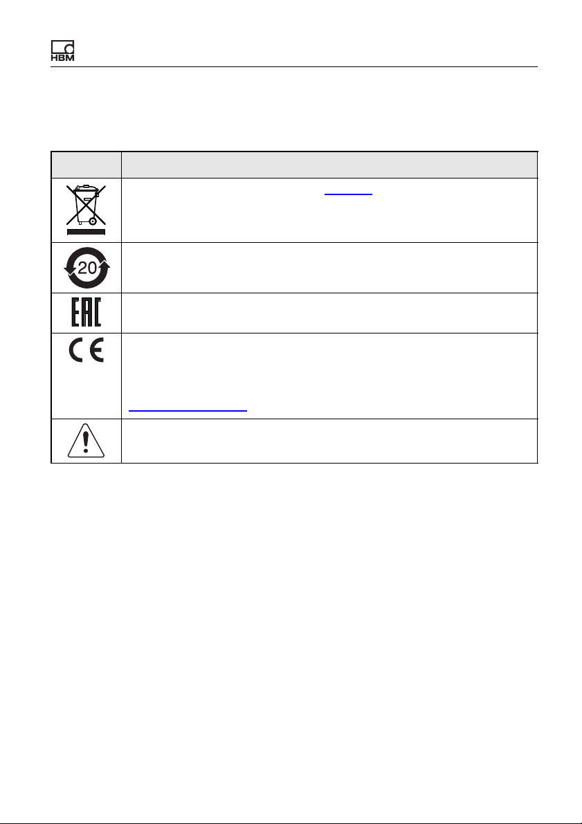
2 Symbols on the instrument
Symbol Meaning
Statutory waste disposal mark, see Disposal.
Statutory mark of compliance with emission limits in electronic equipment
supplied to China
Marking certifying approval for sale of the device in the Russian Federation.
CE mark
The CE mark enables the manufacturer to guarantee that the product
complies with the requirements of the relevant EC directives. The declaration of conformity can be found on the HBM website
https://www.hbm.com under HBMdoc.
Read and note the information given in this manual.
Symbols on the instrument
ClipX
a4643-1.0 HBM: public 9
Page 12

Symbols on the instrument
10
a4643-1.0 HBM: public ClipX
Page 13

Overview
3 Overview
Make sure you always have, and are using, the documentation version
matching your device. After a firmware update, for example, you can download
the current version of the full documentation from the HBM website:
https://www.hbm.com/ClipX
Acrobat Reader. You can download the Acrobat Reader free of charge from the
Adobe website.
About ClipX
By buying a ClipX measuring amplifier, you have chosen a high-quality HBM
measurement system that is compact, powerful and variable. You can connect
the ClipX via the standard Ethernet port to a PC, and parameterize and control
the device via its internal web server. You can connect to an automation system
via the digital and analog inputs/outputs and/or via one of the fieldbus interfaces
PROFIBUS
®
, PROFINET®, EtherNet/IP™1) or EtherCAT2) (depending on
device type). One input per device is provided for different sensors (strain gage,
voltage, current, potentiometer or Pt100), and you can connect sensors with
zero-wire TEDS or 1-wire TEDS. The device additionally features a peak value
memory, instantaneous value memory, limit value switches, and six calculated
channels, as well as offering the facility to display one signal from each of up to
five additional devices and forward the signals to the interfaces. The ClipX is
normally mounted on a support rail; the mounting materials are supplied.
. To read this documentation you need the Adobe
The ClipX documentation
• Quick Start Guide (supplied)
• This manual in PDF format
• Data sheet listing the technical data
• Online help on the device's internal web server
1)
EtherNet/IP™ is a trademark of ODVA Inc. For more information regarding ODVA, visit
www.odva.org.
2)
EtherCAT® is registered trademark and patented technology, licensed by Beckhoff
Automation GmbH, Germany.
ClipX
a4643-1.0 HBM: public 11
Page 14

Overview
Contents of this manual
This manual has a table of contents at the beginning. The index
at the end of the
manual enables you to search for specific terms. The most frequently asked
questions are summarized in the
FAQs section.
All the marks mentioned in this manual are the property of their respective
owners.
Symbols used in this manual
See also
Safety instructions.
Important: This symbol indicates an important detail or a special feature.
Paragraphs with this symbol provide a tip or explain an interesting feature.
Paragraphs marked by this symbol contain additional information.
12
a4643-1.0 HBM: public ClipX
Page 15

ClipX device types, scope of supply
4 ClipX device types, scope of supply
The ClipX is mounted directly on a support rail, though other mounting methods
are also possible. The ClipX is supplied as standard with easy-fit push-in type
plug terminals. You can also use screw-type plug terminals from Phoenix Contact – see Electrical connections, LEDs
You can connect strain gage full or half bridges, voltage-fed piezo-resistive sensors, current or voltage sensors and currents or voltages, potentiometer transducers or Pt100s to the transducer connector. Two freely configurable digital
input/outputs and an analog output for current or voltage are additionally available.
Important: All basic settings are made via the web server integrated
into the ClipX and your web browser. The web server includes its own
help, which explains all the ClipX settings. Depending on the design,
you can also connect the ClipX to various fieldbuses.
4.1 Device types
.
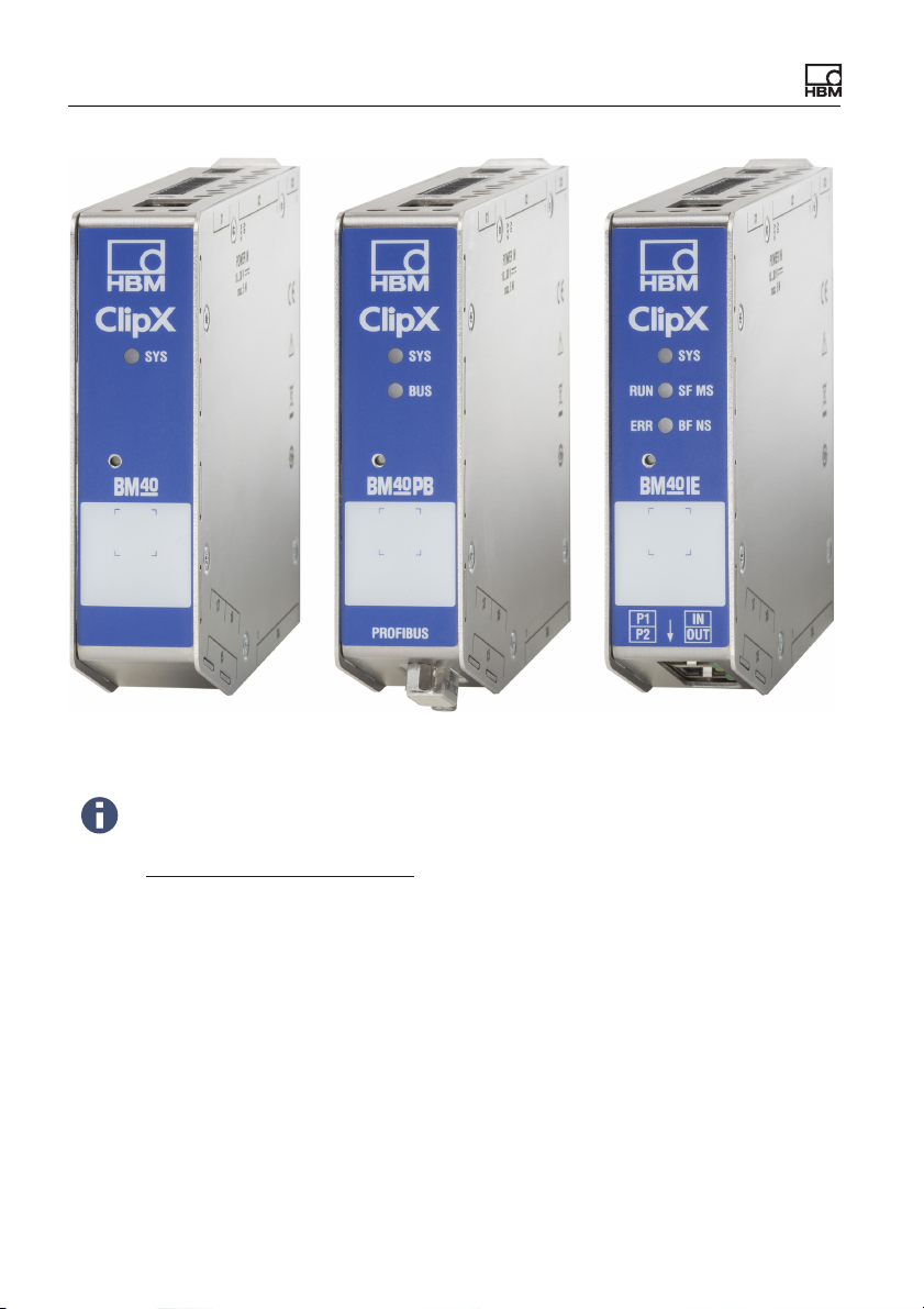
The ClipX comes in three different design versions. All the design versions feature the same sensor inputs, two freely configurable digital input/outputs, and an
analog output switchable for current (4 … 20mA) or voltage (±10V):
1. BM40
This version does not include a fieldbus.
2. BM40PB
This version includes a PROFIBUS
®
interface.
3. BM40IE
You can operate this version with a PROFINET
2)
EtherCAT
1)
EtherNet/IP™ is a trademark of ODVA Inc. For more information regarding ODVA, visit
www.odva.org.
2)
EtherCAT® is registered trademark and patented technology, licensed by Beckhoff
Automation GmbH, Germany.
ClipX
®
interface. The interfaces can be switched using the software.
a4643-1.0 HBM: public 13
®
, EtherNet/IP™1) or
Page 16
ClipX device types, scope of supply
Fig. 1: The ClipX device types from left to right: BM40, BM40PB and BM40IE
To aid the design process, pre-compiled ePLAN macros (licensefree) and 3D-STEP files are available free of charge at
https://www.hbm.com/ClipX.
14
a4643-1.0 HBM: public ClipX
Page 17

ClipX device types, scope of supply
4.2 Scope of supply
• ClipX with mounted support rail holder.
• Bag containing three plug terminals, ordering number 1-CON-S1019 for
sensor connection (13-pin), supply, digital I/O and ClipX bus (12-pin) as well
as the analog output (3-pin). You can also order this plug terminal set separately.
• A Quick Start Guide with safety instructions (a4838).
You can download a full operating manual as well as additional information resources from the HBM website:
https://www.hbm.com/ClipX. Pre-compiled ePLAN macros (license-
free) and 3D-STEP files to aid the design process are also available
to download. To read this documentation you need the Adobe Acrobat Reader. You can download the Acrobat Reader free of charge
from the
Adobe website.
ClipX
a4643-1.0 HBM: public 15
Page 18
ClipX device types, scope of supply
25
35
132.6
111. 7
127.7
118.6
100
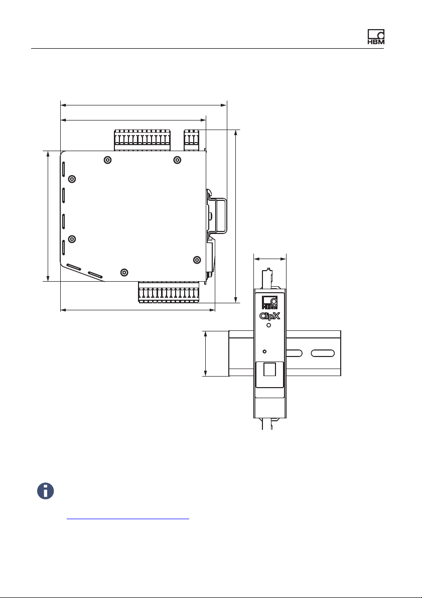
4.3 Dimensions
Fig. 2: ClipX dimensions when mounted on support rail (DIN rail 35mm to DIN
EN 60715) with 16mm depth, all measures in mm
To aid the design process, pre-compiled ePLAN macros (licensefree) and 3D-STEP files are available free of charge at
https://www.hbm.com/ClipX.
16
a4643-1.0 HBM: public ClipX
Page 19
Mounting
5 Mounting
The ClipX is designed for mounting on a support rail (35mm DIN rail to DIN
EN 60715). You can choose different mounting methods if you want though. The
support rail on which you mount the ClipX may be 8.5 or 16mm deep.
Important: You must ground the support rail.
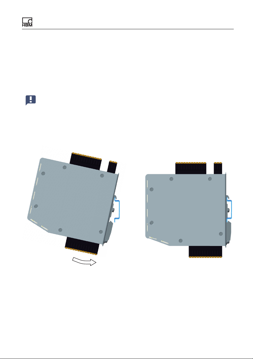
5.1 Mounting on a support rail
Fig. 3: Mounting on a support rail
1. Hang the ClipX from the top edge of the support rail.
2. Push the ClipX onto the support rail in the direction of the arrow as shown in
the picture.
The clip at the bottom secures the ClipX by a spring.
ClipX
a4643-1.0 HBM: public 17
Page 20
Mounting
1
2
3
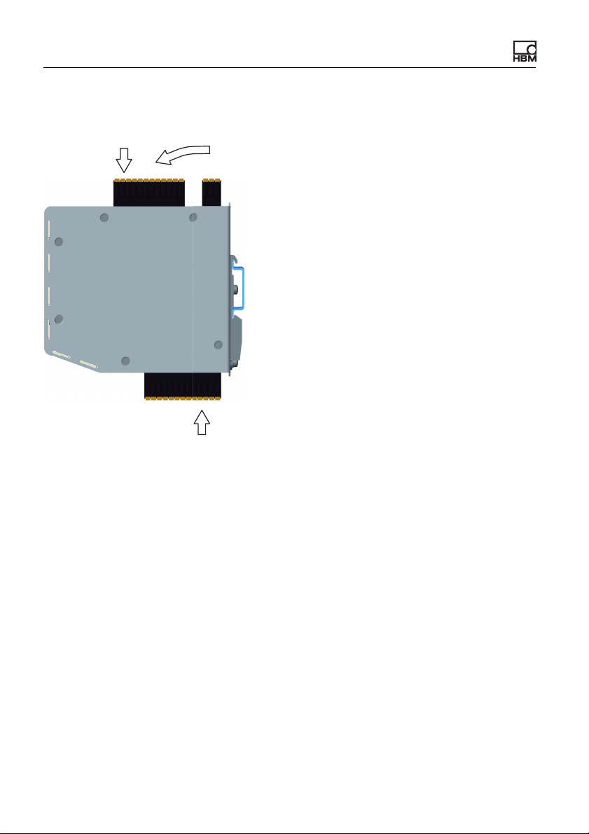
5.2 Dismounting from a support rail
Fig. 4: Dismounting from a support rail
1. Push the ClipX up.
The spring mechanism allows you to release it from the top locator on the
support rail.
2. Tilt the ClipX forward, rotating it as you do so.
3. Detach the ClipX downwards.
18
a4643-1.0 HBM: public ClipX
Page 21
Mounting
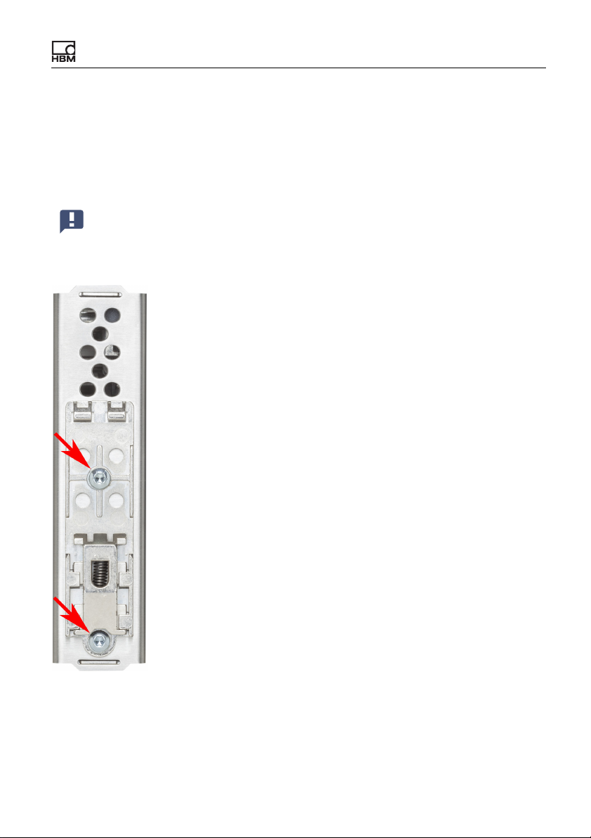
5.3 Other mounting options
Instead of using a support rail, you can mount the ClipX on a wall, for example,
using an appropriate bracket. To do so, make a mounting bracket to fit on the
back of the ClipX.
Important: The vents on the back must not be covered over. The minimum clearance between the back of the device and a wall in the area
of the vents is 8mm.
Fig. 5: Screws to remove the support rail mount
ClipX
a4643-1.0 HBM: public 19
Page 22

Mounting
Procedure
1. Use a size T10 Torx screwdriver to remove the screws indicated in the picture.
2. Keep the screws, because you should reuse them.
3. Make your mounting bracket.
The material should be about 1 to 2mm thick, to enable you to reuse the
original (M3) screws. The space between the two screws is 43.7 mm.
4. Fix your mount either using the original screws or using M3 screws penetrating a maximum of 5mm into the housing. Fasten the screws only handtight.
Important: You must ground the ClipX housing, such as by way of the
mount.
20
a4643-1.0 HBM: public ClipX
Page 23

Electrical connections, LEDs
6 Electrical connections, LEDs
The ClipX features IP20 protection in accordance with EN 60529 (protection
against touch by fingers; protection against foreign bodies of Ø > 12mm).
The ClipX is supplied as standard with easy-fit push-in terminals. But you can
also obtain screw-type terminals from Phoenix Contact
(https://www.phoenixcontact.com
– MC 1.5/3-ST-3.5 BK for the analog output,
– MC 1.5/12-ST-3.5 BK for the power supply, digital I/O, ClipX bus and syn-
chronization of the TF amplifiers,
– MC 1.5/13-ST-3.5 BK for connection of sensors.
Other variants, such as with locking clips, are also available from Phoenix Con-
tact, e.g. MCVW 1.5/…, MCVR 1.5/…, FK-MCP 1.5/…
The clamping range of the plug terminals is 0.2mm
(AWG16). If you need to connect multiple wires to one terminal, adapt the wire
cross-sections accordingly. Use 10mm wire end ferrules (without plastic collars)
to connect the wires to the terminals wherever possible.
The plug terminals can be protected against interchanging by the supplied
coding pins. To do so, plug a coding pin into one of the slots in the device
sockets and remove the lug of the corresponding connection on the plug terminal.
) (BK = black variant), e.g.:
2
(AWG24) to 1.5mm2
To aid the design process, pre-compiled ePLAN macros (licensefree) and 3D-STEP files are available free of charge at
https://www.hbm.com/ClipX.
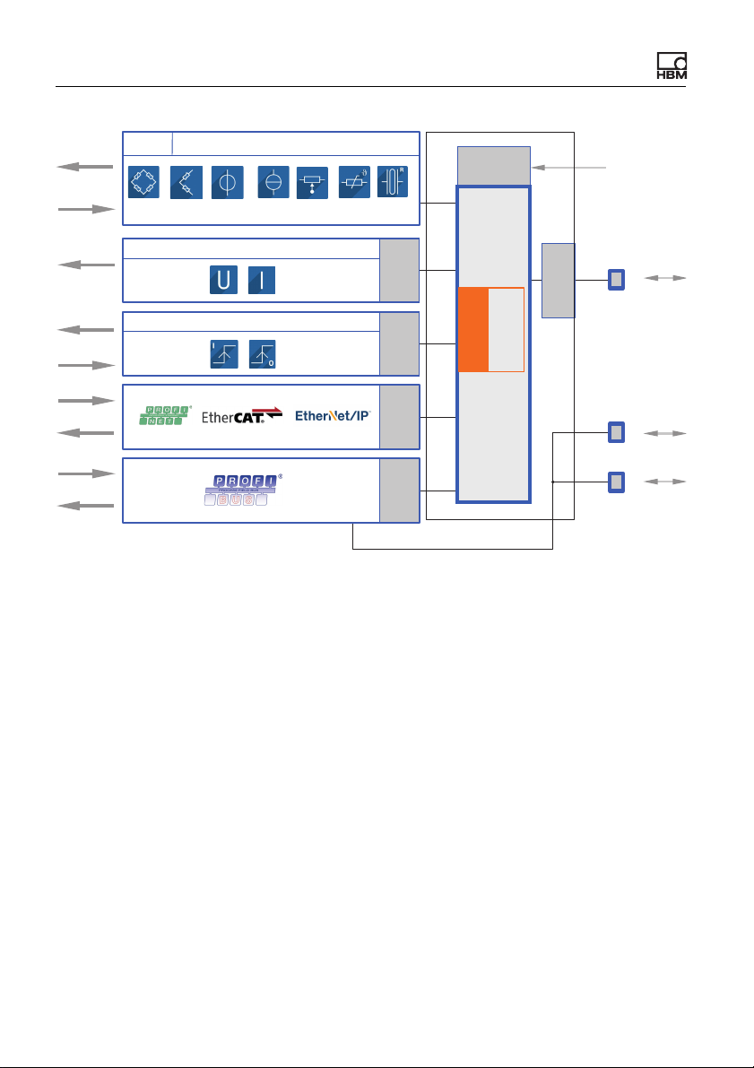
6.1 Functionality (block diagram)
The following diagram presents the functionality and interaction of the various
inputs and outputs of the ClipX. The electrical isolation of the various function
blocks is also shown: there is electrical isolation between the power supply and
all signal inputs and outputs.
ClipX
a4643-1.0 HBM: public 21
Page 24
Electrical connections, LEDs
Galvanic
isolation
TEDS
Transducer
DC / CF
Signal
Signal
Signal
DO 1/2
DO GND
DI 1/2
DI GND
Signal
Bridge
excitation
Galvanic
isolation
Galvanic
isolation
Galvanic
isolation
Analog output
Digital I/Os
FPU
Floating point
unit
Galvanic
isolation
Galvanic
isolation
Ethernet
ClipX SYNC
24 V
0 V
ClipX bus
CPU
Fig. 6: Function blocks and electrical isolation of the ClipX
Electrical isolation of the GND connections
The following connections are electrically isolated from each other:
• DI, GND (Ground) Digital-In: Reference potential for DI1 and DI2.
• X, GND ClipX bus: Reference potential for ClipX bus (CxA, CxB) and Sync;
on the BM40PB PROFIBUS-GND is also connected by this.
• AI, GND Analog-In: Reference potential for U-In and I-In; the adjacent measurement inputs for voltage and current.
• S GND for the inner shield on double-shielded cable; with 1-wire TEDS,
TEDS (–) is also connected here.
• AO, GND Analog-Out: Reference potential for the analog output.
22
a4643-1.0 HBM: public ClipX
Page 25
Electrical connections, LEDs
S
S
S
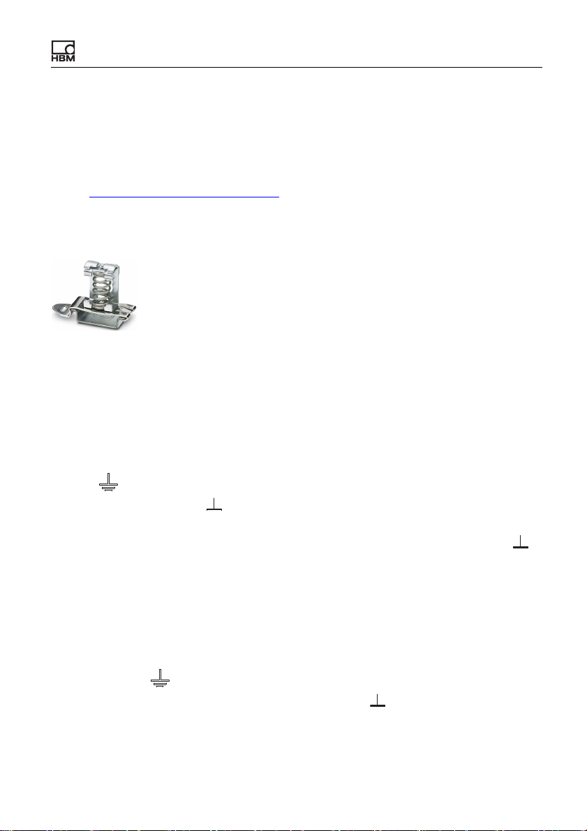
6.2 Shielding and grounding design
The supply voltage connection, as well as the signal and sense leads, must be
installed in such a way that electromagnetic interference does not adversely
affect module functionality (HBM recommendation: “Greenline shielding design”
– see http://www.hbm.com/Greenline
shortest possible length to the plug terminals and, as far as possible, lay the
shield flat at the control cabinet inlet with shield connection terminal blocks, e.g.
type SKS 8-SNS35 – 3062786 from Phoenix Contact – see illustration.
Fig. 7: Shield connection terminal block for flat contacting of cable shields (ex-
ample)
Double-shielded connecting cables, e.g. for sensors
We recommend using HBM cable Kab 7.5/00-2/2/2 wherever possible. The
cable is double-shielded and low in capacitance. When using double-shielded
cables, connect the outer shield only to the connection for the housing (ground
). Always connect the cable shield by the
symbol , labeled “Outer cable shield” in the connection diagrams), not to one
of the GND connections ( ). In the case of control cabinets, also lay this shield
contacting on the cabinet – see illustration of shield clamp. Connect the inner
shields of the sensor cables to the connection labeled “Inner cable shield” ( ).
Use the shortest lines possible for the connections.
Applications in areas with potentially explosive atmospheres are exceptions.
There connect all cable shields to the potential equalization connection.
Single-shielded cables
Connect the shields of single-shielded cables to the connection for the housing
(ground symbol , labeled “Outer cable shield” or “Cable shield” in the connection diagrams), not to one of the GND connections ( ). In the case of control
cabinets, also lay this shield contacting on the cabinet – see illustration of shield
clamp.
ClipX
a4643-1.0 HBM: public 23
Page 26
Electrical connections, LEDs
Grounding
Important: You must ground the support rail on which you mount the
ClipX. If you want to mount the ClipX in a different way, such as on a
wall, you must ground the housing by way of the mount.
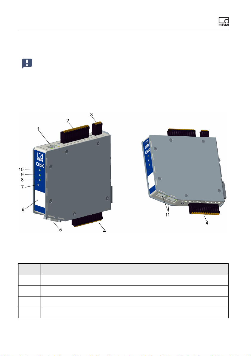
6.3 Available connections and LEDs
Fig. 8: Locations of the connections and LEDs; the connector designations X1
to X7 are imprinted on the housing; for meanings see table.
No. Description
1 X1: Ethernet port
2 X2: Power supply, Digital I/O, ClipX bus
3 X3: Analog output
4 X4: Transducer connection, TEDS
24
a4643-1.0 HBM: public ClipX
Page 27

Electrical connections, LEDs
No. Description
5 X5: Fieldbus, here PROFIBUS (only BM40PB)
6 HBM calibration label and free labeling space
7 Reset button
Fieldbus LED 1, only BM40IE; EtherCAT: ERR, PROFINET: BF, Ether-
8
Net/IP™: NS
Fieldbus LED 2, only BM40IE and BM40PB; EtherCAT: RUN, PROFINET:
9
SF, EtherNet/IP™: MS; PROFIBUS: BUS
10 System LED
X6, X7: 2 x RJ45; P1/IN (X7) and P2/OUT (X6) for EtherNet/IP™ or PROF-
11
INET or EtherCAT (only BM40IE)
See also Electrical connections, LEDs for plug terminals with screw connections.
Electrical isolation of the GND connections
The following connections are electrically isolated from each other:
• DI, GND (Ground) Digital-In: Reference potential for DI1 and DI2.
• X, GND ClipX bus: Reference potential for ClipX bus (CxA, CxB) and Sync;
on the BM40PB PROFIBUS-GND is also connected by this.
• AI, GND Analog-In: Reference potential for U-In and I-In; the adjacent measurement inputs for voltage and current.
• S GND for the inner shield on double-shielded cable; with 1-wire TEDS,
TEDS (–) is also connected here.
• AO, GND Analog-Out: Reference potential for the analog output.
ClipX
a4643-1.0 HBM: public 25
Page 28
Electrical connections, LEDs
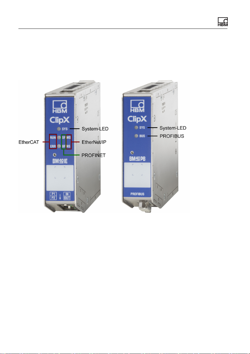
6.4 Health monitoring, LEDs
There are 1 to 3 LEDs on the front, depending on the device type. On the
BM40IE the LEDs have different meanings, indicated by differing labels,
depending on the fieldbus.
Fig. 9: Assignment of the LEDs to the interfaces on the BM40IE and BM40PB.
The BM40 only has the system LED.
The following tables list the states indicated by the LEDs. The LEDs flash about
once a second in flash mode, and about five times a second in rapid-flash
mode.
26
a4643-1.0 HBM: public ClipX
Page 29
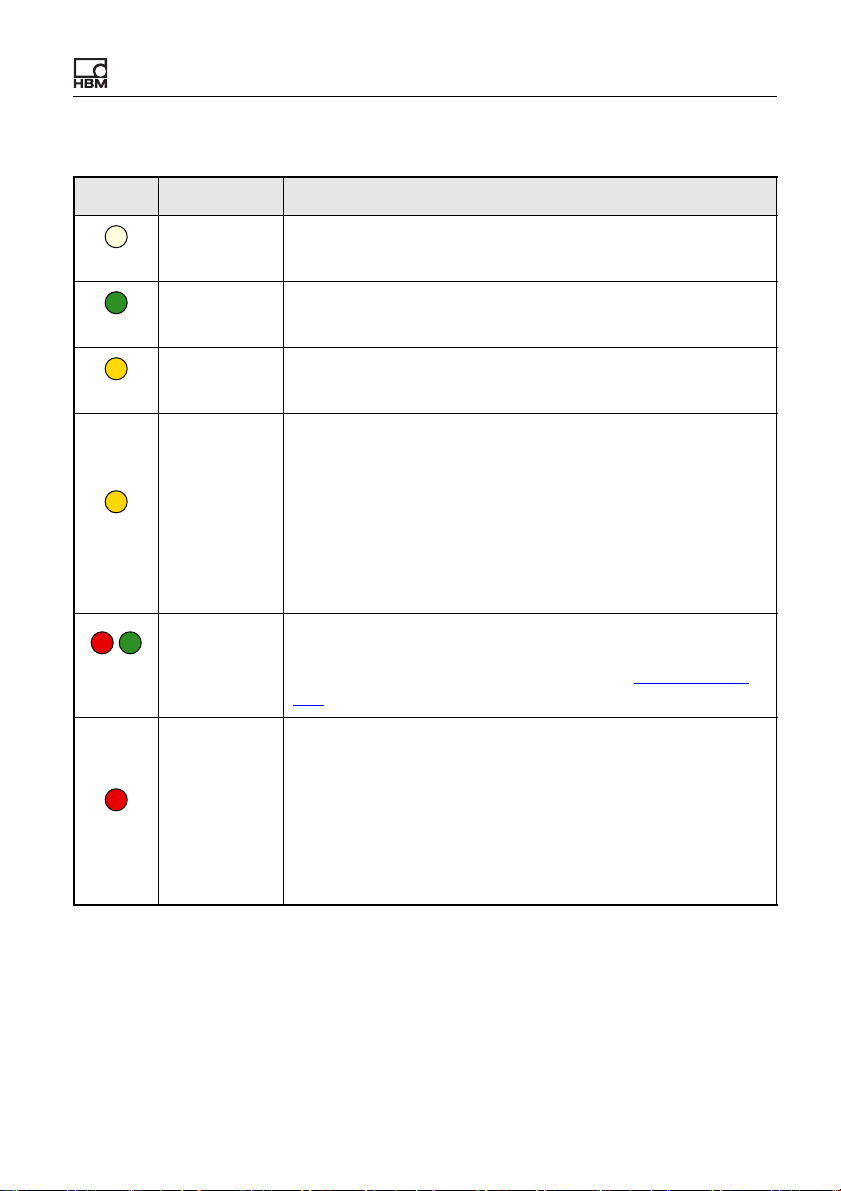
System LED (SYS)
LED Status Meaning
Off No supply voltage, or ClipX defective.
Off
On The ClipX has fully booted up, and is ready.
Green
Flashing Manual device detection (via the browser) has been started.
Yell ow
Error on ClipX bus:
– One or more of the expected devices is not transmitting,
– Errors in data transfer
If an invalid external measurement value is correctly trans-
mitted, it does NOT result in a yellow or red system LED. It
causes an invalid status of the external measurement value
in question (one bit per value).
Yell ow
On
Electrical connections, LEDs
or not responding
Red/
green
Red
ClipX
/
Flashing
Flashing rap-
idly
The ClipX is not ready.
None of the meanings listed above applies. If this state lasts
longer than a few seconds, please contact Technical sup-
port at HBM.
The self-test has failed. This may be due to the following
causes:
– Error in the internal file system
– Error in the A/D converter
– IRQ or DMA error
– Error in the D/A converter
– TEDS error: No communication possible
a4643-1.0 HBM: public 27
Page 30
Electrical connections, LEDs
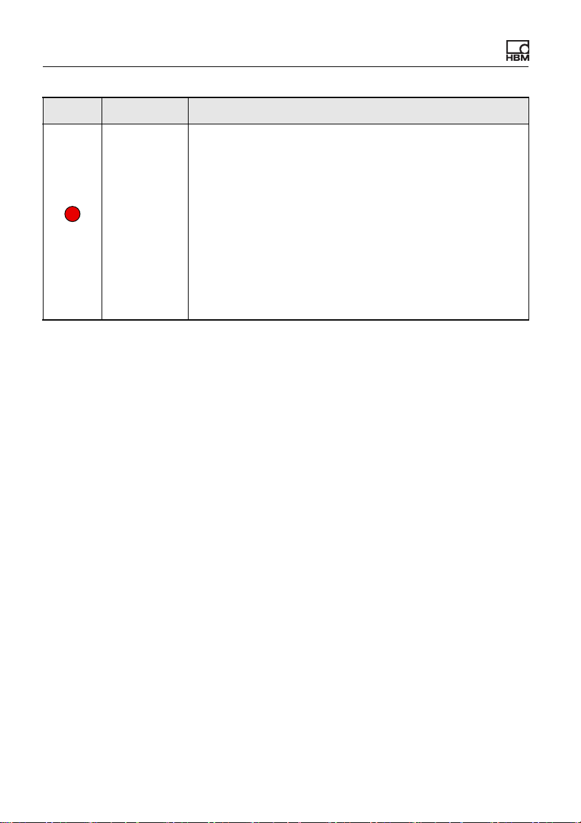
LED Status Meaning
The ClipX is booting up (initializing everything)
or
The parameter set is being changed
or
One or more of the following measured values is invalid:
– Raw value of A/D converter
– Filtered value of A/D converter
– Fieldbus value
– Process value, gross
– Process value, net
– Analog output (e.g. overflow)
Red
On
28
a4643-1.0 HBM: public ClipX
Page 31

EtherCAT LEDs (RUN, ERR, only BM40IE)
Electrical connections, LEDs
RUN
LED
Off
Green
ERR
LED
Off
Red
Status Meaning
Off The ClipX is in the INIT state.
Flashing at
2.5Hz
Single flash The ClipX is in the SAFE-OPERATIONAL state.
On The ClipX is in the OPERATIONAL state.
The ClipX is in the PRE-OPERATIONAL state.
Status Meaning
Off No error.
The EtherCAT communication is running and error-free.
Flashing
(2.5Hz)
Single flash Local error: The ClipX has autonomously changed the
Invalid configuration.
Possible cause: A change specified by the master is not
possible.
EtherCAT status.
Possible causes:
– A host watchdog timeout has occurred,
– synchronization error. In this case the device switches
automatically to the SAFE-OPERATIONAL state.
ClipX
Double flash A process data watchdog timeout has occurred.
Possible cause: A synchronization timeout (Sync Manager
watchdog).
a4643-1.0 HBM: public 29
Page 32

Electrical connections, LEDs
PROFINET LEDs (SF, BF, only BM40IE)
SF
LED
Off
Red
BF
LED
Off
Red
Status Meaning (system error LED)
Off No error.
Flashing
(1Hz, 3 sec-
onds)
On Watchdog timeout.
A DCP signal service is triggered over the bus.
There is a system error, or a channel, generic or extended
diagnosis.
Status Meaning (bus error LED)
Off No error.
Flashing
(2Hz)
On Error: No configuration, slow physical connection or no con-
No data exchange.
nection.
30
a4643-1.0 HBM: public ClipX
Page 33

EtherNet/IP™ LEDs (MS, NS, only BM40IE)
Electrical connections, LEDs
MS
LED
Off
Green
/
Red/
green
Red
NS
LED
Off
Status Meaning
Off The ClipX is not on.
Flashing
(1Hz)
On The ClipX is running and error-free.
Flashing
(1Hz)
Flashing
(1Hz)
On Serious error: There is an irreparable error. Please contact
Standby: The ClipX has not been configured.
The ClipX is running a self-test.
Simple error: The ClipX has detected a reparable error, e.g.
an incorrect configuration.
Technical support at HBM.
Status Meaning
Off The ClipX is not on, or has no IP address.
Green
Red/
green
ClipX
Flashing
(1Hz)
On The ClipX is connected to a network device, e.g. a switch.
/
Flashing
(1Hz)
No network connection. But the ClipX has been assigned
an IP address.
The ClipX is running a self-test.
a4643-1.0 HBM: public 31
Page 34

Electrical connections, LEDs
NS
LED
Red
Status Meaning
Flashing
(1Hz)
On Duplicate IP address.
Connection timeout.
One or more connections to this ClipX are in timeout. This
status will only be terminated when all connections have
been restored or you reset the ClipX.
The ClipX has detected that the IP address assigned to it
(and set) is already being used in the network.
PROFIBUS LED (BUS, only BM40PB)
LED
BUS
Off
Green
Status Meaning
Off The ClipX is not on, or the network has no power.
Flashing
cyclically
(2Hz)
On The ClipX is in the RUN state; cyclic communication is run-
The master is in the CLEAR state.
ning.
32
Red
Flashing
briefly (1Hz)
Flashing
cyclically
(2Hz)
On Incorrect PROFIBUS-DP configuration.
The ClipX is not configured.
The ClipX is in the STOP state.
No communication; a connection error has possibly
occurred.
a4643-1.0 HBM: public ClipX
Page 35

Electrical connections, LEDs
Note
Plug terminal X2, supply, DIO, Sync, ClipX bus
X
Housing
ClipX bus
ClipX bus GND
ClipX bus
Synchronization
Sync
Digital In GND
Digital In 2
DI2
DI1
DI
DO2
DO1
Digital In 1
Digital Out 2
Digital Out 1
Supply 0 V
0V
24V
Supply 10 … 30 V
CxA
CxB
6.5 Connecting the supply voltage
Connect the supply voltage from 10 to 30VDC to terminal X2 (top).
See also Available connections and LEDs
.
Voltages above 30V
can destroy the ClipX.
DC
Make sure that the supply voltage is between 10 and 30V
Fig. 10: Supply voltage at plug terminal X2
DC
.
For each ClipX you must provide a power output of 5W plus the power required
for analog and digital outputs. Use an appropriately dimensioned cable for the
supply voltage, so as to avoid an excessive voltage drop when operating multiple devices. We recommend using wire end ferrules and a cable cross-section
of 1.5mm
ClipX
2
(AWG16).
a4643-1.0 HBM: public 33
Page 36

Electrical connections, LEDs
6.6 Connecting transducers
Important: Refer to the information on the connection clamps (Avail-
able connections and LEDs) and cable shielding (Shielding and
grounding design).
The signals of the connected sensor or signal are digitized by the ClipX at
19.2kHz. You can view various signal processing data values in your browser:
• the field value, i.e. the input signal,
• the ADC value, i.e. the signal of the A/D converter in digits,
• the filtered ADC value, i.e. the signal of the A/D converter based on your
selected filter, also in digits,
• the gross signal, i.e. the signal after zero balancing and scaling,
• the net signal, i.e. the signal after taring.
The taring level is located in the signal path after the gross signal. Normally the
taring function is only required for weighing applications, such as to record the
content and total weight of a container.
6.6.1 Strain gage full and half bridge, voltage-fed piezo-resistive sensors
The use of TEDS is not yet supported by the current firmware version.
It will be in one of the future versions however.
When connecting transducers in a 6-wire configuration, you can also use zerowire TEDS instead of the 1-wire TEDS connection. In this case the TEDS
module is looped into the sense lines.
See also Available connections and LEDs
34
a4643-1.0 HBM: public ClipX
, Shielding and grounding design.
Page 37

Electrical connections, LEDs
3
2
14
rd
wh
gy
bk
gn
bu
Pt100
TEDS
Pt100
Cable wire colors (HBM transducer):
Plug terminal X4, transducer connection
bu = blue; gn = green; gr = gray;
rd = red; bk = black; wh = white;
1
2'
3
3'
2
I
U
AI
S
4
Measurement signal +
Sense lead -
Bridge excitation voltage +
Sense lead +
Bridge excitation voltage -
Outer cable shield
Inner cable shield
Measurement signal -
1-Wire-TEDS
1
2
Strain gage full bridge, voltage-fed piezo-resistive sensors in 6-wire configuration (1-wire TEDS)
Fig. 11: Plug terminal X4, 6-wire pin assignment, TEDS optional
ClipX
a4643-1.0 HBM: public 35
Page 38

Electrical connections, LEDs
Pt100
TEDS
Pt100
Cable wire colors (HBM transducer):
Plug terminal X4, transducer connection
bu = blue; gn = green; gr = gray;
rd = red; bk = black; wh = white;
1
2'
3
3'
2
I
U
AI
S
4
Measurement signal +
Sense lead -
Bridge excitation voltage +
Sense lead +
Bridge excitation voltage -
Outer cable shield
Inner cable shield
Measurement signal -
Zero-Wire-TEDS
3
2
14
rd
wh
gy
bk
gn
bu
TEDS
Strain gage full bridge, voltage-fed piezo-resistive sensors in 6-wire configuration (zero-wire TEDS)
Fig. 12: Plug terminal X4, 6-wire pin assignment, TEDS optional
36
a4643-1.0 HBM: public ClipX
Page 39

Electrical connections, LEDs
3
2
1
wh
gy
bk
gn
bu
Pt100
TEDS
Pt100
1
2'
3
3'
2
Measurement signal +
Sense lead -
Bridge excitation voltage +
Sense lead +
Bridge excitation voltage -
I
U
AI
S
Outer cable shield
Cable wire colors (HBM transducer):
bu = blue; gn = green; gr = gray;
rd = red; bk = black; wh = white;
Plug terminal X4, transducer connection
Inner cable shield
4 Measurement signal -
1-Wire-TEDS
1
2
Strain gage half bridge in 6-wire configuration (1-wire TEDS)
Fig. 13: Plug terminal X4, 6-wire pin assignment, TEDS optional
ClipX
a4643-1.0 HBM: public 37
Page 40

Electrical connections, LEDs
Pt100
TEDS
Pt100
1
2'
3
3'
2
Measurement signal +
Sense lead -
Bridge excitation voltage +
Fühlerleitung +
Bridge excitation voltage -
I
U
AI
S
Outer cable shield
Cable wire colors (HBM transducer):
bu = blue; gn = green; gr = gray;
bk = black; wh = white;
Plug terminal X4, transducer connection
Inner cable shield
4 Measurement signal -
Zero-Wire-TEDS
3
2
1
wh
gy
bk
gn
bu
TEDS
Strain gage half bridge in 6-wire configuration (zero-wire TEDS)
Fig. 14: Plug terminal X4, 6-wire pin assignment, TEDS optional
38
a4643-1.0 HBM: public ClipX
Page 41

Electrical connections, LEDs
3
2
14
rd
wh
bk
bu
Pt100
TEDS
Cable wire colors (HBM transducer):
bu = blue; gn = green; gr = gray;
rd = red; bk = black; wh = white;
Plug terminal X4, transducer connection
Feedback bridges for 4-wire circuitry
1
2'
3
3'
2
I
U
AI
S
4
Measurement signal +
Sense lead -
Bridge excitation voltage +
Sense lead +
Bridge excitation voltage -
Cable shield
Measurement signal -
1-Wire-TEDS
1
2
Strain gage full or half bridge in 4-wire configuration
When connecting in a 4-wire configuration, you can only use 1-wire TEDS (as
shown in the diagram).
Important: When connecting in a 4-wire configuration, you must connect the inputs of the sense lines via jumpers to the supply voltage
outputs, otherwise the measurement value will always be invalid.
Fig. 15: Plug terminal X4, 4-wire pin assignment; pin 4 is not used for half bridge
circuits, TEDS optional
ClipX
a4643-1.0 HBM: public 39
Page 42

Electrical connections, LEDs
Pt100
TEDS
Pt100
Plug terminal X4, transducer connection
HBM cable KAB7.5/00-2/2/2
Cable wire colors:
bu = blue; gn = green; gr = gray;
rd = red; bk = black; wh = white;
1
2'
3
3'
2
I
U
AI
4
Measurement signal +
Sense lead -
Bridge excitation voltage +
Sense lead +
Bridge excitation voltage -
Cable shields
Measurement signal -
Potential equalization
Explosion hazard
area
Safe
area
3
2
14
rd
wh
gy
bk
gn
bu
S
851
4
Z961H
851
4
Z961
851
4
Z961H
6.6.2 Strain gage full bridge for applications in areas with potentially
explosive atmospheres
It is not possible to use transducers with TEDS when using Zener barriers.
Use cable KAB 7.5/00-2/2/2 and safety barriers 1-SD01A from HBM to connect
transducers in areas with potentially explosive atmospheres to the ClipX. The
connection resistance of the sensor (or of multiple parallel configured sensors)
must be between 80 and 350Ohms.
See also Available connections and LEDs
.
Strain gage full bridge in 6-wire configuration
Fig. 16: Plug terminal X4, 6-wire pin assignment
40
Important: Observe the permissible cable lengths depending on the
excitation voltage and transducer resistance, the safety instructions
for the Zener barrier SD01A, and the rules for operating plant in areas
with potentially explosive atmospheres.
a4643-1.0 HBM: public ClipX
Page 43

6.6.3 Potentiometric transducer
3
2
1wh
gy
bk
gn
bu
Pt100
TEDS
Pt100
Plug terminal X4, transducer connection
1
2'
3
3'
2
I
U
AI
S
4
Measurement signal +
Sense lead -
Bridge excitation voltage +
Sense lead +
Bridge excitation voltage -
Outer cable shield
Inner cable shield
Measurement signal -
1-Wire-TEDS
1
2
The use of TEDS is not yet supported by the current firmware version.
It will be in one of the future versions however.
Electrical connections, LEDs
See also Available connections and LEDs
Fig. 17: Plug terminal X4, pin assignment for potentiometric transducer
Important: Connect the sense leads to the corresponding excitation
voltage leads by wire bridges (2 at 2' and 3 at 3') if you are not using
a 6-wire configuration (with 5 wires assigned). Otherwise a sensor error will be signaled, and you will not be able to measure (invalid mea-
, Shielding and grounding design.
sured value).
ClipX
a4643-1.0 HBM: public 41
Page 44

Electrical connections, LEDs
1 4, 3'
ϑ
1-Wire-TEDS
Pt100
TEDS
Pt100
1
2
Plug terminal X4, transducer connection
1
2'
3
3'
2
I
U
AI
S
4
Measurement signal +
Sense lead -
Bridge excitation voltage +
Sense lead +
Bridge excitation voltage -
Cable shield
GND
Measurement signal -
6.6.4 Temperature measurement by Pt100
The use of TEDS is not yet supported by the current firmware version.
It will be in one of the future versions however.
With the ClipX, temperatures can be measured in degrees Celsius, Kelvin or
Fahrenheit using a Pt100 resistor. The cable resistance is adjusted by way of
the sense line.
See also Available connections and LEDs
.
Fig. 18: Plug terminal X4, pin assignment for Pt100
42
a4643-1.0 HBM: public ClipX
Page 45

6.6.5 Voltage source (±10V)
U
1-Wire-TEDS
Pt100
TEDS
Pt100
1
2
Plug terminal X4, transducer connection
1
2'
3
3'
2
I
U
AI
S
4
Measurement signal +
Sense lead -
Bridge excitation voltage +
Sense lead +
Bridge excitation voltage -
Cable shield
Analog GND
Voltage input
Current input
Measurement signal -
GND
The use of TEDS is not yet supported by the current firmware version.
It will be in one of the future versions however.
Electrical connections, LEDs
See also Available connections and LEDs
Fig. 19: Plug terminal X4, pin assignment for electrical voltage source
.
ClipX
a4643-1.0 HBM: public 43
Page 46

Electrical connections, LEDs
I
Plug terminal X4, transducer connection
1-Wire-TEDS
TEDS
Pt100
1
2
1
2'
3
3'
2
I
U
AI
S
4
Measurement signal +
Sense lead -
Bridge excitation voltage +
Sense lead +
Bridge excitation voltage -
Cable shield
Analog GND
Voltage input
Current input
Measurement signal -
GND
6.6.6 Current source (±20mA or 4 … 20mA)
The use of TEDS is not yet supported by the current firmware version.
It will be in one of the future versions however.
See also Available connections and LEDs
Fig. 20: Plug terminal X4, pin assignment for current source
.
44
a4643-1.0 HBM: public ClipX
Page 47

6.6.7 Current drain (4 … 20mA)
Digital In 2
DI2
DI1
DO2
DO1
Digital In 1
Digital Out 2
Digital Out 1
Supply 0 V
0V
24V
Supply 10 … 30 V
AI
Plug terminal X4, transducer connection
Plug terminal X2
1-Wire-TEDS
TEDS
Pt100
1
2
1
2'
3
3'
2
S
4
Measurement signal +
Sense lead -
Bridge excitation voltage +
Sense lead +
Bridge excitation voltage -
Cable shield
Measurement signal -
I
U
Analog GND
Current input
Voltage input
GND
Sensor
The use of TEDS is not yet supported by the current firmware version.
It will be in one of the future versions however.
Electrical connections, LEDs
See also Available connections and LEDs
Fig. 21: Plug terminals X2 and X4, pin assignment for current drain
.
ClipX
a4643-1.0 HBM: public 45
Page 48

Electrical connections, LEDs
DI2
DI1
DI
DO2
DO1
0V
24V
X
Plug terminal X2, supply, DIO, Sync, ClipX bus
Housing, cable shield optional
ClipX bus
ClipX bus GND
ClipX bus
Sync Synchronization
Digital In GND
Digital In 2
Digital In 1
Digital Out 2
Digital Out 1
Supply 0 V and Digital Out GND
Supply 10 … 30 V
CxA
CxB
LOW: 0 V … 5 V
HIGH: 10 V … 30 V
6.7 Connecting the digital inputs and outputs
The digital inputs and the flags or bits for the outputs are analyzed after 1ms at
the latest in the event of a change.
See also Available connections and LEDs
Digital inputs
.
Fig. 22: Plug terminal X2, pin assignment of digital inputs
The digital inputs must be switched against a positive voltage (≥10V). An open
input will be detected as LOW.
46
a4643-1.0 HBM: public ClipX
Page 49

Digital outputs
DI2
DI1
DO2
DO1
0V
24V
X
DI
Plug terminal X2, supply, DIO, Sync, ClipX bus
Housing, cable shield optional
ClipX bus
ClipX bus GND
ClipX bus
Synchronization
Digital In GND
Digital In 2
Digital In 1
Digital Out 2
Digital Out 1
Supply 0 V and Digital Out GND
Supply 10 … 30 V
CxA
Sync
CxB
Electrical connections, LEDs
Fig. 23: Plug terminal X2, pin assignment of digital outputs
Start-up behavior of the digital outputs
On starting up the ClipX (power on), each output initially has a high output resistance. After initializing, the status of the settings is determined in the Start
parameter set. When an output is active, the supply voltage (10 … 30V) is
switched through to it.
The factory default setting is: Output deactivated.
ClipX
a4643-1.0 HBM: public 47
Page 50

Electrical connections, LEDs
AO
AO
analog output
Analog-Out ‒
Cable shield
Analog-Out +
6.8 Connecting the analog output
You can output voltage (±10V) or current (4 … 20mA). The analog output is
short-circuit-proof, the bandwidth is 3.8kHz, the update rate is 19.2kHz.
See also Available connections and LEDs
Fig. 24: Plug terminal X2, pin assignment for analog output
Start-up behavior
On starting up the ClipX (power on), the analog output initially has a high output
resistance. After initializing, the status of the settings is determined by the Boot
parameter set.
The factory default setting is: Output deactivated, gross signal as input (source),
zero value 0V, scaling 0/0 and 5/5, value in case of “invalid” signal 0 V and test
signal 0V (both inactive).
.
Value in case of error
Which value is outputted depends on whether you activate the value in case of
an “invalid” signal or not. Make the setting via the ClipX web server in your
browser.
1. Value in case of “invalid” signal active (switch in browser on the right and
red)
If the input signal becomes invalid, or the output signal would be outside the
range of ±11V or less than 3mA or greater than 21mA, the specified value is
outputted.
2. Value in case of “invalid” signal not active (switch in browser on the left and
gray)
The highest or lowest possible value is outputted depending on the signal
(±11V, or 3mA or 21mA).
48
a4643-1.0 HBM: public ClipX
Page 51

Electrical connections, LEDs
SYS
SF MS
BF NS
RUN
ERR
BM40IE
OUT
IN
P2
P1
max. 30 cm
PROFIBUS
SYS
40
PB
BUS
BM
SYS
40
BM
SYS
40
BM
6.9 Using multiple ClipX devices, ClipX bus
You can transfer one measured value with status from each of up to six other
ClipX devices over the ClipX bus to a ClipX and then capture them simultaneously with the values of that device. The connections use line topology. The
maximum cable length between two devices is 30cm.
Interconnect the CxA terminals and CxB terminals respectively of up to six
devices. Lay the lines from the first device to the second, from the second to the
third device, etc. (line topology). The ClipX bus GND connection is additionally
required. The CxA and CxB lines must be twisted and shielded.
See also Available connections and LEDs
amplifiers.
, Synchronizing multiple ClipX CF
Fig. 25: Transferring a measured value from multiple ClipX devices
The ClipX bus synchronizes automatically. All you have to do is enter the
highest address (Highest Address) (number of devices) and the Own Address
a4643-1.0 HBM: public 49
ClipX
Page 52

Electrical connections, LEDs
Housing, cable shields
ClipX bus
ClipX bus GND
ClipX bus
Synchronization
Sync
Sync
Digital In GND
Digital In 2
DI2
DI1
DI
DO2
DO1
Digital In 1
Digital Out 2
Digital Out 1
Supply 0 V
0V
24V
Supply 10 … 30 V
CxA
CxB
CxA
CxB
X
X
DI2
DI1
DI
DO2
DO1
0V
24V
Plug terminal X2, supply, DIO, Sync, ClipX bus
(location where the own device is to appear) in your browser (ClipX Bus menu).
Address 1 serves as the bus master; all the other addresses are slaves. Specify
which signal to transmit for each device. The status (valid/invalid) is transmitted
along with the measurement signal. 1000 values per second are transmitted per
device (including CRC check).
If you set Own Address for a device to 0, the ClipX bus will be deactivated for that device, meaning no other devices are visible, and no
own signal can be transmitted.
Fig. 26: Plug terminal X2, pin assignment for ClipX bus
50
Important: Termination resistors are not necessary, and must not be
used. The maximum line length between two devices is 30cm.
a4643-1.0 HBM: public ClipX
Page 53

Electrical connections, LEDs
SYS
SF MS
BF NS
RUN
ERR
BM40IE
OUT
IN
P2
P1
max. 30 cm
PROFIBUS
SYS
40
PB
BUS
BM
SYS
40
BM
SYS
40
BM
6.10 Synchronizing multiple ClipX CF amplifiers
You should synchronize multiple ClipX devices that supply sensors with carrier
frequency (CF) so that the carrier frequency measuring amplifiers do not interfere with each other. This will prevent crosstalk between adjacent sensor
cables, resulting in disturbance to measurements. If you are using only sensors
with direct voltage (DC) amplifiers, no synchronization is necessary.
To synchronize, interconnect the Sync terminals of the devices and the ClipX
bus GND terminals, unless you have already connected the latter to transmit
measured values. Lay the lines from the first device to the second, from the
second to the third device, etc. (line topology). The cable must have twisted-pair
wires, and be shielded. The ClipX bus GND and Sync lines must be twisted and
shielded.
See also Available connections and LEDs
bus.
, Using multiple ClipX devices, ClipX
Fig. 27: Synchronizing multiple ClipX devices
a4643-1.0 HBM: public 51
ClipX
Page 54

Electrical connections, LEDs
Housing, cable shields
ClipX bus
ClipX bus GND
ClipX bus
Synchronization
Sync
Sync
Digital In GND
Digital In 2
DI2
DI1
DI
DO2
DO1
Digital In 1
Digital Out 2
Digital Out 1
Supply 0 V
0V
24V
Sipply 10 … 30 V
CxA
CxB
CxA
CxB
X
X
DI2
DI1
DI
DO2
DO1
0V
24V
Plug terminal X2, supply, DIO, Sync, ClipX bus
Important: On the first device you must enable Sync Mode Master
[Master sync mode]. All the others operate as slaves, so the switch
must not be active. Make the setting in your browser using the Am-
plifier and Sensor Type menu items. Synchronization is only possible for sensor types with carrier frequency (CF), not for DC. No
synchronization of the time base or the A/D converters takes place.
Fig. 28: Plug terminal X2, pin assignment for Sync signal
a4643-1.0 HBM: public ClipX
Important: Termination resistors are not necessary, and must not be
used. The maximum line length between two devices is 30cm.
52
Page 55

Electrical connections, LEDs
A/D converter
(ADC)
Filter
1)
ADC unfiltered
ADC filtered
Field value (el. value)
Gross value
Net value
Minimum
2)
Maximum
2)
Peak-to-peak
2)
Limit value switch
2)
Analog output
3)
min. 52 μs
1)
Filter off: 0 s; Bessel filter: 0.43/fg; Butterworth filter: 0.66/fg; The result is time in seconds for an
output signal of 50% of the full scale value with a jump at the input.
2)
These signals can also use other sources. The phase delays of the source signals must then be
added.
3)
If the analog output is to output a value from this group, you must add on 52 μs. If you are using
a source from a different group, you must add the phase delay of the source signal to the 52 μs.
260 μs
6.11 Signal propagation times within the ClipX and over the ClipX bus
The various modules in the ClipX are combined into a number of groups, each
with fixed cycle times. This makes it easier to calculate the total propagation
time of a signal. The following diagrams indicate the propagation times of the
various groups as well as any potential additions you might need to allow for the
hardware of inputs/outputs. To calculate the maximum propagation time of signals running through more than one group, such as min/max values obtained
from calculated channels, simply add together the propagation times of the
respective groups.
Pay attention to the sequencing of the analysis within a group. If source signals
are formed only later in the group, this will double the propagation time until the
result is available.
Group 1: Measured values
Fig. 29: Minimum propagation time for group 1: 52µs plus A/D converter conver-
sion time
ClipX
a4643-1.0 HBM: public 53
Page 56

Electrical connections, LEDs
1 ms
Flags and
values from
fieldbus
Digitale
inputs
Computed
channels
Digital flags
(I/O flags)
1)
Digital
outputs
2)
ClipX bus:
Start
transfer
3)
1)
Changes in digital flags are analyzed in the following order: Zeroing, taring, clear zero value,
clear tare value, reset limit value switch, reset peak values, hold held values, clear hold values.
3)
Asynchronous transfer of the values on the ClipX bus is complete after max. 1 ms, i.e on the next
cycle.
2)
The digital outputs have an additional response time of max. 0.25 ms.
Some signals might also have sources from other groups. For example, the
analog output might deliver a signal from the ClipX bus. In these cases,you
must add the propagation time of the source signal's group in order to get the
total propagation time.
Example 1
Propagation time from input, e.g. 10V, 20mA or DC full/half bridge, to analog
output (10V) with a Bessel filter at 1kHz:
• A/D converter (ADC): 260µs
• Filter: 0.43/1000 = 430µs
• Analog output: 52µs
Added to this is a jitter of up to 52µs, as the A/D converter only starts a new con-
version every 52µs. So the total propagation time is 742 … 797µs.
Group 2: Flags, Digital I/Os, calculated values, ClipX bus
Fig. 30: Maximum propagation time for group 2: 1ms
Example 2
Propagation time from input (see group 1) to a digital output with a Bessel filter
at 1kHz, limit value switch at half the step height.
• A/D converter (ADC): 260µs
• Filter: 0.43/1000 = 430µs
•Group 2: 1ms
• Digital output: max. 250µs response time
54
a4643-1.0 HBM: public ClipX
Page 57

Electrical connections, LEDs
Polling rate
EtherCAT/
PROFINET
ca. 250 μs250 μs
1)
1 ms
1)
At 4 kHz frame rate.
ClipX
fieldbus
controller
Period duration
of frame rate
of fieldbus
Polling rate
EtherNet/IP /
PROFIBUS
0.25 … 1 ms
Added to this is a jitter of up to 52µs, as the A/D converter is not synchronized
with group 1. In the best case, a value is available at the start of the analysis in
group 2 and can be outputted directly at the digital output for example. So the
total propagation time is 940 … 1992µs.
Example 3
Propagation time of a value from the ClipX bus via a limit value switch to a digital output.
• ClipX bus: 1ms
• Limit value switch: 52µs
• Digital output: 1ms plus max. 250µs response time
This result in a total propagation time of 2.3ms. However, you must add the
propagation time in the device that places the value on the ClipX bus in order to
get the time from the sensor until a response occurs.
Group 3: Data from fieldbus master to ClipX
Fig. 31: Propagation time for group 3
ClipX
a4643-1.0 HBM: public 55
Page 58

Electrical connections, LEDs
Update rate
EtherCAT/
PROFINET
250 μs
1)
1 ms
1)
At 4 kHz frame rate.
Update rate
EtherNet/IP/
PROFIBUS
approx. 250 μs 0.25 … 1 ms
ClipX
fieldbus
controller
Period duration
of frame rate
of fieldbus
Group 4: Data from ClipX to fieldbus master
Fig. 32: Propagation time for group 4
56
a4643-1.0 HBM: public ClipX
Page 59

Starting up the ClipX
7 Starting up the ClipX
The first section of this chapter explains the general power-up and operating
behavior of the ClipX following a successful installation. Then the steps required
to put the ClipX into operation are explained. For initial start-up, you should connect the ClipX via Ethernet to a PC. The description of operation via one of the
fieldbuses can be found in chapter Operation via fieldbus
If you want to operate multiple ClipX devices, you should first connect
each ClipX device individually to a PC and perform a basic configuration (e.g. IP address and Name).
Then read the section headed
plifiers so as to avoid interference between the devices.
Synchronizing multiple ClipX CF am-
7.1 Power-up and operating behavior
When the ClipX is powered up, all the inputs and output remain at 0 or 0.0V as
appropriate. The start parameter set is loaded and activated first (= initialization). As soon as the ClipX has initialized, the outputs are set to the preset or
calculated values (factory setting for the digital outputs: 0, not inverted). If the
analog output is inactive, the output has a high internal resistance. If the source
signal for the analog output is invalid, the specified value in case of an invalid
signal is outputted (factory setting 11V but disabled).
The digital inputs and outputs and the calculations are updated at the sampling
rate (1000Hz). The signal at the analog output is updated at 19.2kHz. If the
source signal has a smaller rate of change, the value is outputted multiple times.
Values are transferred from synchronized ClipX devices at a maximum of 1000
values per second, so with six connected device you get 6000 values per
second. The maximum time delay between the ClipX values transmitted over
the ClipX bus is 1ms.
.
ClipX
Up to three clients (PCs) can connect to a ClipX; any further connection is then rejected.
a4643-1.0 HBM: public 57
Page 60

Starting up the ClipX
Important: Some browsers make more than one connection. In this
case, the number of possible additional connections is reduced.
See also Using parameter sets.
7.2 Connecting via Ethernet
Connecting
You have two options for connecting to the ClipX:
1. Make a direct 1:1 connection.
Connect your PC and the ClipX by an Ethernet cable. In rare cases, you will
need an Ethernet cross cable for this. Normally the PC will adapt automatically to the cable.
2. Connect over a network.
Connect your PC to the network or switch, and connect the ClipX in turn to
the network or switch – in each case using an Ethernet cable.
Important: The transfer of commands and data is not encrypted or secure (no https). So you should only operate the ClipX in an internal
network with no connection to the Internet or – if an Internet connection is essential – connect via a VPN tunnel.
In both cases, your PC should use the DHCP setting (Obtain an IP address
automatically) to connect. With fixed IP addresses this is only possible if the
PC and ClipX are using addresses from the same network segment (ClipX factory default setting: DHCP). The connections use IPv4; IPv6 is not supported.
Use the first variant if you want to use multiple ClipX devices. First connect to each individual ClipX, and assign each one a unique device
name through your web browser. This will enable you to identify the individual ClipX devices later, otherwise (depending on the connection
method you use) it will not always be possible to distinguish between
them.
58
a4643-1.0 HBM: public ClipX
Page 61

Starting up the ClipX
Connecting
1. Launch your web browser.
The latest versions of Firefox, Chrome and Microsoft Internet Explorer (version 11 or higher) are supported and have been tested by HBM.
2. Enter ClipX/ or http://ClipX/ or http://ClipX.local in the address bar.
The Home page is displayed.
Important: Do not use https; only http.
If you have already changed the device name, you must enter the new name in
place of ClipX. If you have forgotten the name, try one of the alternative options.
Click on in the header and the SYS LED on the ClipX you are using
will flash red/green.
Alternative options
If the method described above does not work, in Windows 7 or higher you can
try the following (detect via UPnP):
1. Open Windows Explorer.
2. Click on Network.
3. In the Other devices section you should see the ClipX device (with the
device name, factory default ClipX).
4. Double-click on the icon.
If you know the device's IP address, you can also type it in your browser's
address bar, e.g. http://192.168.169.130.
Install one of the following apps from the Google Play Store if you want to connect the ClipX using Android:
ClipX
a4643-1.0 HBM: public 59
Page 62

Starting up the ClipX
https://play.google.com/store/apps/details?id=com.hbm.devices.scan.ui.android
https://play.google.com/store/apps/details?id=com.tjjang.upnptool
https://play.google.com/store/apps/details?id=com.melloware.zeroconf
The apps use different connection methods – see also No device found?
Under Linux you can also type one of the following lines to call up a list of ClipX
devices and their IP addresses or MAC addresses respectively and enter them
in your browser:
$ nmblookup clipx
$ avahi-browse --all
Which line works is dependent on which method (NetBIOS or Bonjour) you are
able to use, i.e. what software is installed on your PC.
7.2.1 No device found?
If no connection is made, there may be a number of reasons.
General reasons
• Is the device actually on (connected to the power supply)?
• Is the system LED on the ClipX lit? See also Health monitoring, LEDs.
• Is the interface cable connected?
• Have you enabled the correct interface or correct interface adapter on the
PC?
Problems with the interface
• Are you using the correct Ethernet cable?
Use an Ethernet switch with a standard cable or a direct connection by a
cross cable.
• Is your Ethernet switch operating correctly?
If you are not operating any other devices on the switch with which you can
check the function, try to set up a direct connection between the PC and the
measuring device.
60
a4643-1.0 HBM: public ClipX
Page 63

Starting up the ClipX
• Have you waited long enough for the PC to specify its address?
If the PC cannot find a server in the network, the search for the server looks
in the DHCP setting (Obtain an IP address automatically) first of all. (The
icon for the interface in the Windows 7 tray indicates the search, but the icon
might only appear if it is configured to do so. In Windows 8 and higher it is
no longer displayed.) It then takes about 30 seconds before an automatic
address or the specified alternative address (if any) is set. No device is
found during this time.
• Is it possible that your firewall is blocking the connection?
Try deactivating your firewall or open the following ports:
• For communication with the device via a browser, TCP ports 80 and
8081 are required.
• Different ports are required to locate the ClipX depending on the variant.
For UPnP TCP 80 and UDP-Multicast at IP address 239.255.255.250
(sending and receiving) with port 1900, for NetBIOS UDP 137, for Avahi
or Zeroconf (similar to Bonjour) UDP-Multicast is required at IP address
224.0.0.251 (sending and receiving) with port 5353.
• If a WLAN is also active with your PC, test whether the device is found when
you temporarily switch off the WLAN (only for the time of the scan). With
some WLAN configurations, problems can occur if multiple Ethernet ports
are enabled.
• If your PC has several Ethernet interfaces, try deactivating all other Ethernet
interfaces.
• If you are using the device in a large network, contact your network adminis-
trator. There are a series of options in managed networks to limit or completely prevent data transmission between the individual nodes. Administrative access control settings may therefore by needed here.
Notes
• In Windows XP only the name resolution under NetBIOS is available.
• For name resolutions via NetBIOS, you should only ever connect one ClipX
as long as you have not changed the device names.
ClipX
a4643-1.0 HBM: public 61
Page 64

Starting up the ClipX
• UPnP is only available as from Windows 7.
• Avahi or Zeroconf (similar to Bonjour) is only available if a corresponding
service, such as Bonjour print services, is installed.
See also Possible cases and their effects when connected via Ethernet,
Set Ethernet address of PC.
7.2.2 Possible cases and their effects when connected via Ethernet
When connecting between the PC and ClipX the following cases may arise:
1. No server in the network, the PC has no address (DHCP is used), and the
ClipX is likewise set to DHCP (factory default setting).
When using Windows XP or higher, temporary addresses are automatically
assigned by the PC (APIPA), the ClipX connection can be made.
2. No server in network, PC has no setting or is using DHCP, the ClipX has a
fixed address
No connection can be established with this combination.
3. No server in the network, PC and ClipX have a fixed address
A connection can normally be made only if the addresses of the PC and
ClipX are in the same network segment and both are using the same subnet
mask.
4. DHCP server in network, PC has a fixed address or uses DHCP, the ClipX
has a fixed address.
A connection can normally be made only if the addresses of the PC and
ClipX are in the same network segment.
5. DHCP server in network, PC and ClipX are using DHCP
The connection can be established.
62
a4643-1.0 HBM: public ClipX
Page 65

Starting up the ClipX
7.2.3 Set Ethernet address of PC
Procedure for Windows 10
1. Use the icon in the notification area of the task bar to open the Network
and Internet Settings (right mouse button).
2. In the Change network settings section click on Change adapter options.
3. Right click on the relevant adapter (port), select Properties and specify an
Administrator account or confirm the security prompt.
4. Select Internet protocol version 4 (TCP/IPv4) and click on Properties.
5. Activate Use the following IP address and enter an address with which the
first three groups of numbers match the groups of numbers of the HBM
device and only the last group of numbers contains a different number
between 1 and 254. The last group of numbers must not match the one on
the HBM device.
6. For Subnet mask enter the same groups of numbers as are present on the
HBM device.
7. Then click OK or Close to close all open dialogs.
See also Example
.
Procedure for Windows 8/8.1
1. From the Charms menu on the Windows desktop (not in tile view) open
Settings -> Control Panel -> Network and Sharing Center (View by:
Small icons) or Show network status and tasks (View by: Categories).
2. Click in the Show active networks area on the connection you want (usu-
ally LAN connection).
3. Click on Properties and specify an administrator account or confirm the
confirmation prompt.
4. Select Internet protocol version 4 (TCP/IPv4) and click on Properties.
5. Activate Use the following IP address and enter an address with which the
first three groups of numbers match the groups of numbers of the HBM
device and only the last group of numbers contains a different number
between 1 and 254. The last group of numbers must not match the one on
the HBM device.
ClipX
a4643-1.0 HBM: public 63
Page 66

Starting up the ClipX
6. For Subnet mask enter the same groups of numbers as are present on the
HBM device.
7. Then click OK or Close to close all open dialogs.
See also Example
.
Procedure for Windows 7
1. Use the Windows Start menu to open the Control Panel -> Network and
Sharing Center (View by: Small icons) or Show network status and
tasks (View by: Categories).
2. Click in the Show active networks area on the connection you want (usually LAN connection).
3. Click on Properties and specify an administrator account or confirm the
confirmation prompt.
4. Select Internet protocol version 4 (TCP/IPv4) and click on Properties.
5. Activate Use the following IP address and enter an address with which the
first three groups of numbers match the groups of numbers of the HBM
device and only the last group of numbers contains a different number
between 1 and 254. The last group of numbers must not match the one on
the HBM device.
6. For subnet mask enter the same digit groups as those available on the
HBM device.
7. Then click OK or Close to close all open dialogs.
See also
Example.
Procedure for Windows XP
1. Use the Windows Start menu to open Settings -> Network connections.
From the context menu (right-click), choose the Properties of the relevant
LAN connection.
2. Select Internet protocol (TCP/IP) and click on Properties.
3. Activate Use the following IP address and enter an address with which the
first three groups of numbers match the groups of numbers of the HBM
device and only the last group of numbers contains a different number
64
a4643-1.0 HBM: public ClipX
Page 67

Starting up the ClipX
between 1 and 254. The last group of numbers must not match the one on
the HBM device.
4. For subnet mask enter the same digit groups as those available on the
HBM device.
5. Then click OK to close all open dialogs. You may have to restart the PC to
activate the setting.
Example
The IP address of the ClipX is 192.168.169.80, the subnet mask is
255.255.255.0.
Enter 192.168.169.123 as the IP address and 255.255.255.0 as the subnet
mask on the PC.
ClipX
a4643-1.0 HBM: public 65
Page 68

Starting up the ClipX
7.2.4 Resetting Ethernet network settings
You can reset the Ethernet network settings (and only them) to their factory
defaults:
1. Switch off the power supply.
2. Press the Reset button (see picture) using a pencil or a small screwdriver
and keep it pressed while you switch the power back on.
3. Wait for the system LED to start flashing green before releasing the button.
The ClipX will perform a restart automatically.
4. Wait until after the restart is finished before connecting to the device.
Fig. 33: System LED (1) and Reset button (2)
Configuring the Ethernet port after resetting (factory defaults)
• Use DHCP (“Obtain an IP address automatically”, meaning from the server
or via APIPA, i.e. negotiate in the network, if your PC is also using DHCP).
• Device name: ClipX.
• All IP address, subnet mask, gateway or DNS settings are deleted.
66
a4643-1.0 HBM: public ClipX
Page 69

Starting up the ClipX
7.3 Setting the ClipX using a web browser
Click on to switch language.
You make all the settings for sensors and signal processing in your browser.
You can view help on each topic by pressing F1 or clicking on . Click on
to make the SYS LED of the ClipX being used flash red/green if you have connected multiple ClipX devices.
After making the ClipX device settings in your browser, save them all to
your PC by choosing Device Storage from the menu.
7.4 Ethernet API
The Ethernet API (Application Programming Interface) is a programming interface by which you can send data via the Ethernet port to the ClipX. The data are
then displayed in the browser, and can be polled over the fieldbuses. You can
program an Ethernet API yourself for example.
7.5 Using parameter sets
You can store up to 10 parameter sets in the ClipX. A parameter set contains
almost all the settings of the various menus for Amplifier (sensors), Calculated
Channels, Peak Values and Limit Switches etc. It does not include the net-
work settings, the settings for the fieldbus, the ClipX bus settings or settings for
synchronization of the CF amplifiers.
You can also transfer the parameter sets together with the other device settings
to your PC. Give the parameter sets names so that you can distinguish them
more easily. You can use up to 30 characters per name.
ClipX
a4643-1.0 HBM: public 67
Page 70

Starting up the ClipX
The active parameter set is indicated by ACTIVE, and the start parameter
set by
BOOT.
on the second line in the panel indicates that the original settings of
the current parameter set are no longer being used. Save the settings to
a parameter set so as not to lose them.
You can save, load and activate parameter sets via the web browser or the
fieldbus interface, or activate them only via the digital inputs.
Processing parameter sets
On a new ClipX all the parameter sets contain the factory setting. You can reset
to those defaults at any time by clicking on
FACTORY SETTINGS in the
browser while a parameter set is active.
When the ClipX powers up, all the parameter sets are translated into the rele-
vant binary instructions and stored in the RAM in order to enable quick parameter set changing. Then the start parameter set is activated.
Each parameter set is assigned a check digit (CRC, cyclic redundancy check) in
the RAM in order to avoid errors.
It takes just a few milliseconds to change the active parameter set. However, in
the event of a parameter set switch which changes sensor settings, filters or the
analog output, the measured value status is set to
INVALID for approximately
2.5 seconds so as to suppress transient responses on the outputs. Brief timeouts may also occur on the ClipX bus (SYS LED turns yellow).
68
a4643-1.0 HBM: public ClipX
Page 71

Operation via fieldbus
5 DGND
4 CNTR-P
3 Bus B
2 Not connected
1 Not connected
DGND 9
Bus A 8
Not connected 7
+5 V 6
8 Operation via fieldbus
The following sections are only relevant for the BM40IE and BM40PB device
variants. The BM40 has no fieldbus.
You will find the device description files for cyclic data traffic between the PLC
and ClipX on the HBM website: https://www.hbm.com/ClipX
8.1 Connecting the fieldbus
The ClipX operates on all fieldbuses as a slave; it cannot be operated as a
master.
See also
Pin assignment for BM40PB, PROFIBUS
Available connections and LEDs.
.
Fig. 34: X5: Pin assignment for PROFIBUS
ClipX
Important: You must fit termination resistors at the start and end of
the PROFIBUS network. The resistors are not fitted in the ClipX.
There is, however, a PROFIBUS connector which contains the resistors.
a4643-1.0 HBM: public 69
Page 72

Operation via fieldbus
X7
X6
IN
OUT
EtherCAT master or
EtherCAT slaves
X7
X6
Port 1
Port 2
EtherNet/IP™ master or
EtherNet/IP™ slaves or
switch
Pin assignment for BM40IE, EtherCAT
Fig. 35: X6, X7: Pin assignment for EtherCAT
Important: The connections are not equivalent. Pay attention to the
specified direction IN/OUT.
Pin assignment for BM40IE, EtherNet/IP™
Fig. 36: X6, X7: Pin assignment for EtherNet/IP™
70
a4643-1.0 HBM: public ClipX
Page 73

Operation via fieldbus
X7
X6
Port 1
Port 2
PROFINET master or
PROFINET slaves or
switch
Pin assignment for BM40IE, PROFINET
Fig. 37: X6, X7: Pin assignment for PROFINET
8.2 Data types used by the ClipX
The table below contains the abbreviations used in the command descriptions
for the data types.
Abbreviation Description
REAL, FLOAT 32 bits, floating-comma number
SINT 8 bits, integer signed
INT 16 bits, integer signed
DINT 32 bits, integer signed
USINT 8 bits, integer unsigned
UINT 16 bits, integer unsigned
UDINT 32 bits, integer unsigned
8.3 Data transfer from the controller to the ClipX
See also Data types used by the ClipX.
The following table sets out the data and the speed at which the data are down-
loaded by the ClipX in the event of a change. The speed (cycle in ms) is not syn-
ClipX
a4643-1.0 HBM: public 71
Page 74

Operation via fieldbus
chronized with the fieldbus, or with PROFINET IRT or EtherCAT Distributed
Clocks. The inputs and outputs of the ClipX are processed out of sync with the
fieldbus. The synchronous modes of the ClipX with these fieldbus systems provide only synchronized data transfer, not processing of the data. The processing
of queries and commands, such as the control word or access to the object dictionary, normally takes additional time. In case of doubt, perform your own time
measurements with your system – see also Signal propagation times within the
ClipX and over the ClipX bus.
Name Format
Fieldbus
value 1
Fieldbus
value 2
Limit value 1
Limit value 2
Limit value 3
Limit value 3
Fieldbus flags UINT 1 16 control flags that can be used universally
Control word UDINT 1 32 control flags with fixed assigned func-
REAL
REAL
REAL
REAL
REAL
REAL
Cycle in
ms
1 The ClipX uses these values like measured
1 Threshold values of the limit value switches.
Function
values, for example in calculated channels
or for the limit value switches.
You can assign these values physical units
for displaying in your browser.
The values have no status information, and
so are always seen by the ClipX as valid.
The ClipX reacts to changes, then the values are applied. They are also applied
when any other value in the data changes
from the controller to the ClipX.
in the ClipX like internal flags, such as to
reset peak values.
These flags are transferred in the digital
flags into bits 32 … 47.
See also sections
flags (I/O status), Data transfer from the
ClipX to the controller.
tions.
The control word in this section.
See
Flags: List of possible I/O
72
a4643-1.0 HBM: public ClipX
Page 75

Operation via fieldbus
Name Format
Parameter set
number
Object dictionary read
request
Object dictionary write
request
Cycle in
ms
UINT 1 Parameter set number.
UINT
(Index)
USINT
(Subindex)
USINT
(Padding)
UINT
(Index)
USINT
(Subindex)
USINT
(Padding)
UDINT
(Value)
1 Read an object in the object dictionary by
1 Write an object in the object dictionary by
Function
Switches the ClipX to the parameter set
with this number. The ClipX only reacts to a
change in this value.
The start value is 0. If you want to switch to
parameter set 0 after the bus starts up, you
must first change the value to unequal to 0.
You can also specify a non-existent parameter set number when doing so.
index and subindex. The padding byte has
no function.
The ClipX only reacts to changes in the
index, subindex or padding byte. It does not
react if the index is = 0x0000 (no operation).
You can only read data objects up to 32 bits
in size.
See also section Data transfer from the
ClipX to the controller.
index and subindex. The padding byte has
no function.
The ClipX only reacts to changes in the
index, subindex, padding byte or value. It
does not react if the index is = 0x0000 (no
operation).
You can only write data objects up to 32 bits
in size.
The value type is defined as UDINT, but you
can also write REAL values. To do so, copy
the value without a cast operation after
value! The table below explains the byte
assignment.
See also section
ClipX to the controller.
Data transfer from the
ClipX
a4643-1.0 HBM: public 73
Page 76

Operation via fieldbus
The following table shows the byte assignment of the object value when
accessing the object dictionary.
Bit 31 … 24 Bit 23 … 16 Bit 15 … 8 Bit 7 … 0
Data object types UDINT, DINT, REAL
Not used Data object types INT, UINT
Not used Data object types
SINT, USINT
The control word
Setting a bit in the control word (Set command) triggers the function specified in
the table. However, all set functions are always executed, even if only one bit is
changed. If, for example, bit 1 (Tare) is already set, taring is triggered again on
every change of one of the other bits. The control word comprises 32 bits; the
bits not listed here are reserved for later upgrades.
The control word is acknowledged by ClipX – see Data transfer from the ClipX
to the controller. If the acknowledgment matches the transmitted control word,
the action has been executed and you can delete the bit.
Bit Function
0 Zero (the gross value)
1 Tare (zero the net value)
2 Reset zero value (= 0)
3 Reset tare value (= 0)
4 Set the 1. Point Electrical in two-point scaling
5 Set the 2. Point Electrical in two-point scaling
6 Hold capture 1
7 Hold capture 2
8 Delete capture 1
9 Delete capture 2
74
a4643-1.0 HBM: public ClipX
Page 77

Operation via fieldbus
Bit Function
10 Reset limit value switch 1
11 Reset limit value switch 2
12 Reset limit value switch 3
13 Reset limit value switch 4
14 Reset maximum, minimum and peak-to-peak value
15 Hold maximum, minimum and peak-to-peak value (as long as this bit is set)
16 Filter fast-track. The filter output jumps to the input value.
ClipX
a4643-1.0 HBM: public 75
Page 78

Operation via fieldbus
8.4 Data transfer from the ClipX to the controller
See also Data types used by the ClipX.
The following table sets out the data and the speed at which the data are
updated by the ClipX in the event of a change. The speed (cycle in ms) is not
synchronized with the fieldbus, or with PROFINET IRT or EtherCAT Distributed
Clocks.
Explanation
ADC value
Electrical
value (field
value)
Gross value Gross signal.
Net value Net signal.
Minimum
value
Maximum
value
Peak-to-peak
value
Captured
value 1
Captured
value 2
ClipX bus
value 1 … 6
Format
REAL 0.052
REAL 1
REAL 1
Cycle in
ms
Explanation
Output signal of the A/D converter in digits.
Input signal in the unit of the measured variable, e.g. in mV/V.
Peak value minimum.
Peak value maximum.
Peak value peak-to-peak.
Captured value 1.
Captured value 2.
Value on the device's ClipX bus with address
1 … 6.
Calculated
value 1 … 6
Limit values
1 … 4
76
REAL 1
REAL
Event-
controlled
Value of calculation channel 1 … 6.
Value of the respective limit value 1 … 4.
a4643-1.0 HBM: public ClipX
Page 79

Operation via fieldbus
Explanation
External Eth.
value 1
External Eth.
value 2
Analog output value
I/O status
low
I/O status
high
Measured
value status
Control word
Parameter
set number
Format
REAL 1
REAL
UDINT
UDINT
UDINT
UDINT 1
UINT
Cycle in
0.052 …
0.052 …
Event-
controlled
ms
1
1
1
Explanation
Value 1 transmitted via the Ethernet API.
Value 2 transmitted via the Ethernet API.
1)
1)
Value of the analog output in V or mA.
See Flags: List of possible I/O flags (I/O sta-
tus).
See Measured value status: List of status
bits.
The echo of the control word – see section
headed
desired function has been triggered when
the received control word is equal to the one
sent.
The number of the active parameter set.
Data transfer to the ClipX. The
Reply when
reading from
the object
dictionary
ClipX
UINT
(Index)
USINT
(Sub-
index)
USINT
(Error)
UDINT
(Value)
Reply to the read request: The value is valid
if Index and Subindex are identical to the
request and the error byte is zero.
1
Value of the reply. The value type is defined
as UDINT, but REAL values are also
returned. To do so, copy the value without a
cast operation after value! The table below
explains the byte assignment.
a4643-1.0 HBM: public 77
Page 80

Operation via fieldbus
Explanation
Reply when
writing to the
object dictionary
1)
The time is dependent on the update rate of the source signal.
Format
UINT
(Index)
USINT
(Sub-
index)
USINT
(Error)
Cycle in
ms
1
Explanation
Reply to the write request: The object has
been successfully written to if Index and
Subindex are identical to the request and the
error byte is zero.
The following table shows the byte assignment of the object value when
accessing the object dictionary.
Bit 31 … 24 Bit 23 … 16 Bit 15 … 8 Bit 7 … 0
Data object types UDINT, DINT, REAL
Not used Data object types INT, UINT
Not used Data object types
SINT, USINT
8.5 Settings for the fieldbuses
The following sections set out the minimum settings you need to make in your
web browser for the respective fieldbuses.
See also
8.5.1 Settings for PROFINET
In your browser, specify the device name (Name of station). The name must be
unique within the network. It may also be easier to specify the IP address and
subnet mask (Netmask) there. Click on
78
Connecting via Ethernet, Setting the ClipX using a web browser.
APPLY to apply the settings. But you
a4643-1.0 HBM: public ClipX
Page 81

Operation via fieldbus
can also set both via your fieldbus controller. Carry out the further configuration
of the fieldbus using your PROFINET configuration tool.
Two DAPs (Device Access Points) are available to you for PROFINET:
• A “fast” DAP with a minimum cycle time of 0.25ms and six free slots.
• A “slow” DAP with a minimum cycle time of 1ms and 30 free slots.
8.5.2 Settings for EtherCAT
You can specify all the settings via your EtherCAT configuration tool.
To configure the ClipX, the EtherCAT master can either use the ESI file or –
without an ESI file – download the object dictionary via the EtherCAT connection
(device scan).
By default, no PDOs are assigned. You must make the PDO assignment yourself. Then activate the download in the master so that the assignment is transferred to the ClipX.
SAFE-OPERATIONAL
The ClipX has no safe output state. On the transition from OPERATIONAL to
SAFE-OPERATIONAL, the EtherCAT-controlled outputs retain their instantaneous value, and are no longer updated in SAFE-OPERATIONAL.
8.5.3 Settings for EtherNet/IP™
First make the network settings in the browser depending on your network configuration:
– DHCP server in network: Set DHCP under Config Control.
– BOOTP server in network: Set BOOTP under Config Control.
– No server in network: Set STATIC under Config Control and specify IP
Address and Netmask (subnet mask). The Gateway setting is optional, and
depends on your network.
Click on
ClipX
APPLY to apply the settings.
a4643-1.0 HBM: public 79
Page 82

Operation via fieldbus
Then select which cyclic I/O data you want to transmit, as no configuration
object exists. Click
APPLY to apply your configuration. When you do so, a run-
ning EtherNet/IP™ connection is closed and is restarted with the changed I/O
image. At the top of the browser window you see the current settings. Import
them manually into your EtherNet/IP™ configuration tool.
You can also download your configuration to your PC as a CSV file for documentation purposes (
DOWNLOAD IO-IMAGE). Depending on your browser set-
ting, you are prompted to select a folder, or the file is saved to your Download
folder. The file is for information purposes only, however, and cannot be reimported.
From the menu choose Device Storage and BACKUP or RESTORE as
appropriate to save the configuration on your PC and transfer it to another device.
8.5.4 Settings for PROFIBUS
In your browser, specify the address of the ClipX on the PROFIBUS. The factory setting is 126 (invalid address). The bit rate is automatically detected by the
ClipX. Carry out the further configuration of the fieldbus using your PROFIBUS
configuration tool.
After configuring the ClipX, you can download the resultant GSD file and the
DPV1 list to the PC:
DOWNLOAD GSD and DOWNLOAD DPV1 LIST.
Depending on your browser setting, you are prompted to select a folder, or the
file is saved to your Download folder.
The names you set for the various signals are applied in the GSD file.
The minimum cycle time (Min_Slave_Intervall) is 0.6ms. If the PROFIBUS controller does not take this value from the GSD file, you must
set it manually.
The DPV1 objects are addressed by way of Slot and Index. Whether a module
has been configured in a ClipX PROFIBUS slot (and if so, which one) is irrele-
80
a4643-1.0 HBM: public ClipX
Page 83

Operation via fieldbus
vant. There are, however, PROFIBUS configuration tools that only send DPV1
requests when there is actually a module in the scanned slot. In this case you
must fill up the empty slots.
CiA404-compliant objects are located in slot 4.
DPV1 objects
R/W: RO = read only, RW = read and write, WO = write only. UINT = unsigned
integer.
The ClipX object directory index and subindex is stated for information purposes
only.
DPV1
No of
bytes
Data
type
R/W Description
ClipX object
directory
Slot Index Index
1 1 4 FLOAT RO ADC FLOAT unfil-
tered
1 2 4 FLOAT RO ADC FLOAT filtered 0x44f0 2
1 3 4 FLOAT RO Field value (electr.
value)
1 4 4 FLOAT RO Gross value 0x44f0 4
1 5 4 FLOAT RO Net value 0x44f0 5
1 6 4 FLOAT RW Min value 0x44f0 6
1 7 4 FLOAT RW Max value 0x44f0 7
1 8 4 FLOAT RO Peak-to-peak value 0x44f0 8
1 9 4 FLOAT RO Captured value 1 0x44f0 9
1 10 4 FLOAT RO Captured value 2 0x44f0 10
1 11 4 FLOAT RO External ClipX 1
value
0x44f0 1
0x44f0 3
0x44f0 11
Sub-
index
ClipX
a4643-1.0 HBM: public 81
Page 84

Operation via fieldbus
DPV1
No of
bytes
Data
type
R/W Description
ClipX object
directory
Slot Index Index
1 12 4 FLOAT RO External ClipX 2
value
1 13 4 FLOAT RO External ClipX 3
value
1 14 4 FLOAT RO External ClipX 4
value
1 15 4 FLOAT RO External ClipX 5
value
1 16 4 FLOAT RO External ClipX 6
value
1 22 4 FLOAT RO Calculated channel 1
value
1 23 4 FLOAT RO Calculated channel 2
value
1 24 4 FLOAT RO Calculated channel 3
value
0x44f0 12
0x44f0 13
0x44f0 14
0x44f0 15
0x44f0 16
0x44f0 22
0x44f0 23
0x44f0 24
Sub-
index
1 25 4 FLOAT RO Calculated channel 4
value
1 26 4 FLOAT RO Calculated channel 5
value
1 27 4 FLOAT RO Calculated channel 6
value
1 28 4 FLOAT RW Ethernet API value 1 0x44f0 28
1 29 4 FLOAT RW Ethernet API value 2 0x44f0 29
1 30 4 FLOAT RW Fieldbus value 1 0x44f0 30
1 31 4 FLOAT RW Fieldbus value 2 0x44f0 31
82
a4643-1.0 HBM: public ClipX
0x44f0 25
0x44f0 26
0x44f0 27
Page 85

Operation via fieldbus
DPV1
No of
bytes
Data
type
R/W Description
ClipX object
directory
Slot Index Index
1 32 4 FLOAT RO Analog output elec-
trical value
1 99 4 UINT32 RO All measval statuses 0x44f4 1
2 1 4 FLOAT RW Discharge rate Min /
second
2 2 4 FLOAT RW Discharge rate Max /
second
2 3 4 FLOAT RO Discharge rate Min
step
2 4 4 FLOAT RO Discharge rate Max
step
2 5 4 UINT32 RO Discharge Min
divider
2 6 4 UINT32 RO Discharge Max
divider
2 7 1 UINT8 RW Signal source
Min/Max
0x44f0 32
0x4021 1
0x4021 2
0x4021 3
0x4021 4
0x4021 5
0x4021 6
0x4020 1
Sub-
index
2 11 4 UINT32 RW Clear Min/Max flags
mask low
2 12 4 UINT32 RW Clear Min/Max flags
mask high
2 13 1 UINT8 RW Clear Min/Max flags
invert
2 14 4 UINT32 RW Hold Min/Max flags
mask low
2 15 4 UINT32 RW Hold Min/Max flags
mask high
ClipX
a4643-1.0 HBM: public 83
0x4022 1
0x4023 1
0x4024 1
0x4025 1
0x4026 1
Page 86

Operation via fieldbus
DPV1
No of
bytes
Data
type
R/W Description
ClipX object
directory
Slot Index Index
2 16 1 UINT8 RW Hold Min/Max flags
invert
2 17 0 --- WO Clear Min/Max com-
mand
2 18 1 UINT8 RW Hold Min/Max
0:normal evaluation
1:hold active
2 43 1 UINT8 RW Captured value 1
filled (1: trigger has
occurred)
2 44 1 UINT8 RW Captured value 2
filled (1: trigger has
occurred)
2 45 1 UINT8 RW Captured value 1
status
0:valid
1: invalid
0x4027 1
0x4028 1
0x4029 1
0x4031 1
0x4031 2
0x4032 1
Sub-
index
2 46 1 UINT8 RW Captured value 2
status
0:valid
1: invalid
2 47 4 UINT32 RW Captured value 1
trigger mask low
2 48 4 UINT32 RW Captured value 2
trigger mask low
2 49 4 UINT32 RW Captured value 1
trigger mask high
2 50 4 UINT32 RW Captured value 2
trigger mask high
84
a4643-1.0 HBM: public ClipX
0x4032 2
0x4033 1
0x4033 2
0x4034 1
0x4034 2
Page 87

Operation via fieldbus
DPV1
No of
bytes
Data
type
R/W Description
ClipX object
directory
Slot Index Index
2 51 1 UINT8 RW Captured value 1
invert trigger
2 52 1 UINT8 RW Captured value 2
invert trigger
2 53 4 UINT32 RW Captured value 1
clear mask low
2 54 4 UINT32 RW Captured value 2
clear mask low
2 55 4 UINT32 RW Captured value 1
clear mask high
2 56 4 UINT32 RW Captured value 2
clear mask high
2 57 1 UINT8 RW Captured value 1
invert clear
2 58 1 UINT8 RW Captured value 2
invert clear
0x4035 1
0x4035 2
0x4036 1
0x4036 2
0x4037 1
0x4037 2
0x4038 1
0x4038 2
Sub-
index
2 59 1 UINT8 RW Captured value 1
valuesource
2 60 1 UINT8 RW Captured value 2
valuesource
2 61 0 --- WO Command CLEAR
captured value 1
2 62 0 --- WO Command CLEAR
captured value 2
2 63 0 --- WO Command
TRIGGER captured
value 1
ClipX
a4643-1.0 HBM: public 85
0x4039 1
0x4039 2
0x403a 1
0x403a 2
0x403b 1
Page 88

Operation via fieldbus
DPV1
No of
bytes
Data
type
R/W Description
ClipX object
directory
Slot Index Index
2 64 0 --- WO Command
TRIGGER captured
value 2
2 101 1 UINT8 RO All statuses limit
switches
2 102 1 UINT8 RO Limit switch 1 status 0x4601 1
2 103 1 UINT8 RO Limit switch 2 status 0x4601 2
2 104 1 UINT8 RO Limit switch 3 status 0x4601 3
2 105 1 UINT8 RO Limit switch 4 status 0x4601 4
2 106 1 UINT8 WO Limit switch Reset
command by mask
(0 … 15)
2 107 1 UINT8 WO Limit switch Reset
command single 1
(1: reset)
2 108 1 UINT8 WO Limit switch Reset
command single 2
(1: reset)
0x403b 2
0x4600 1
0x4602 1
0x4603 1
0x4603 2
Sub-
index
2 109 1 UINT8 WO Limit switch Reset
command single 3
(1: reset)
2 11 0 1 UINT8 WO Limit switch Reset
command single 4
(1: reset)
2 111 4 FLOAT RW Limit switch
threshold 1
2 11 2 4 FLOAT RW Limit switch
threshold 2
86
a4643-1.0 HBM: public ClipX
0x4603 3
0x4603 4
0x4604 1
0x4604 2
Page 89

Operation via fieldbus
DPV1
No of
bytes
Data
type
R/W Description
ClipX object
directory
Slot Index Index
2 113 4 FLOAT RW Limit switch
threshold 3
2 114 4 FLOAT RW Limit switch
threshold 4
2 115 4 FLOAT RW Limit switch
hysteresis 1
2 116 4 FLOAT RW Limit switch
hysteresis 2
2 117 4 FLOAT RW Limit switch
hysteresis 3
2 118 4 FLOAT RW Limit switch
hysteresis 4
2 119 1 UINT8 RW Limit switch source 1 0x4606 1
2 120 1 UINT8 RW Limit switch source 2 0x4606 2
2 121 1 UINT8 RW Limit switch source 3 0x4606 3
2 122 1 UINT8 RW Limit switch source 4 0x4606 4
0x4604 3
0x4604 4
0x4605 1
0x4605 2
0x4605 3
0x4605 4
Sub-
index
2 123 1 UINT8 RW Limit switch mode 1 0x4607 1
2 124 1 UINT8 RW Limit switch mode 2 0x4607 2
2 125 1 UINT8 RW Limit switch mode 3 0x4607 3
2 126 1 UINT8 RW Limit switch mode 4 0x4607 4
2 127 4 UINT32 RW Limit switch reset
mask low 1
2 128 4 UINT32 RW Limit switch reset
mask low 2
2 129 4 UINT32 RW Limit switch reset
mask low 3
ClipX
a4643-1.0 HBM: public 87
0x4608 1
0x4608 2
0x4608 3
Page 90

Operation via fieldbus
DPV1
No of
bytes
Data
type
R/W Description
ClipX object
directory
Slot Index Index
2 130 4 UINT32 RW Limit switch reset
mask low 4
2 131 4 UINT32 RW Limit switch reset
mask high 1
2 132 4 UINT32 RW Limit switch reset
mask high 2
2 133 4 UINT32 RW Limit switch reset
mask high 3
2 134 4 UINT32 RW Limit switch reset
mask high 4
2 135 1 UINT8 RW Limit switch reset
invert 1
2 136 1 UINT8 RW Limit switch reset
invert 2
2 137 1 UINT8 RW Limit switch reset
invert 3
0x4608 4
0x4609 1
0x4609 2
0x4609 3
0x4609 4
0x460a 1
0x460a 2
0x460a 3
Sub-
index
2 138 1 UINT8 RW Limit switch reset
invert 4
3 1 1 UINT8 RW Analog output mode 0x4500 1
3 2 1 UINT8 RW Analog output signal
source
3 3 4 FLOAT RW Analog output scal-
ing source value 1
3 4 4 FLOAT RW Analog output scal-
ing source value 2
3 5 4 FLOAT RW Analog output scal-
ing electr. value 1
88
a4643-1.0 HBM: public ClipX
0x460a 4
0x4500 2
0x4500 3
0x4500 4
0x4500 5
Page 91

Operation via fieldbus
DPV1
No of
bytes
Data
type
R/W Description
ClipX object
directory
Slot Index Index
3 6 4 FLOAT RW Analog output scal-
ing electr. value 2
3 7 4 FLOAT RW Analog output scal-
ing electr. offset
3 8 4 FLOAT RW Analog output electr.
error value
3 9 1 UINT8 RW Analog output USE
electr. error value
3 10 4 FLOAT RW Analog output electr.
test value
3 11 1 UINT8 RW Analog out electr.
test val active
3 13 2 UINT16 RO Analog output sta-
tus details
3 31 4 UINT32 RO Digital flags low 0x4700 1
3 32 4 UINT32 RO Digital flags high 0x4700 2
0x4500 6
0x4500 7
0x4500 8
0x4500 9
0x4500 10
0x4500 11
0x4500 13
Sub-
index
3 36 2 UINT16 RO Digital flags lowest
16 bits
3 36 1 UINT8 RW Digital output 1 delay 0x470b 1
3 37 1 UINT8 RW Digital output 2 delay 0x470b 2
3 38 1 UINT8 RW Digital output 1
invert
3 39 1 UINT8 RW Digital output 2
invert
3 40 1 UINT8 RW Digital input 1
debounce
ClipX
a4643-1.0 HBM: public 89
0x4700 6
0x470c 1
0x470c 2
0x470d 1
Page 92

Operation via fieldbus
DPV1
No of
bytes
Data
type
R/W Description
ClipX object
directory
Slot Index Index
3 41 1 UINT8 RW Digital input 2
debounce
3 61 1 UINT8 RW ClipX bus, my
address 0 … 6
3 62 1 UINT8 RW ClipX bus, highest
address 0 … 6
3 63 1 UINT8 RW ClipX bus, value
index to send 0 …
31
3 64 2 UINT16 RO ClipX bus, cycles per
second
3 65 2 UINT16 RO ClipX bus, restart
counter
3 81 1 UINT8 RW TEDS, select zero /
1-wire-connection
3 82 0 --- WO TEDS, read serial
command from HW
(TID)
0x470d 2
0x4380 1
0x4380 2
0x4380 3
0x4380 4
0x4380 5
0x4300 1
0x4300 52
Sub-
index
3 83 14 STRING RO TEDS, read serial
from buffer (TID)
3 84 1 UINT8 RW TEDS, select data
segment (32 bytes)
3 85 0 --- WO TEDS, read data
segment command
(32 bytes)
3 86 66 STRING RO TEDS, read data
segment (32 bytes)
90
a4643-1.0 HBM: public ClipX
0x4300 53
0x4300 54
0x4300 55
0x4300 56
Page 93

Operation via fieldbus
DPV1
No of
bytes
Data
type
R/W Description
ClipX object
directory
Slot Index Index
3 87 1 UINT8 RW TEDS usage
0: ignore
1: if available
2: force
3 87 1 UINT8 RW TEDS search during
paraset change
0: no
1: yes
3 91 2 UINT16 RO Get active param.
set
3 92 2 UINT16 WO Activate a certain
param. set
3 93 2 INT16 WO Command: Save
param. set to file
3 94 2 UINT16 RW Boot param. set 0x4270 4
3 95 1 UINT8 RW Digital IN switch
mode
0: off
1: digital IN 0
2: digital IN 0+1
0x4300 2
0x4300 3
0x4270 1
0x4270 2
0x4270 3
0x4270 5
Sub-
index
3 96 0 --- WO Command: Activate
factory default
3 97 4 UINT32 RO CRC of currently
used parameters
3 98 0 --- WO Command: Re-
calculate CRC of
currently used
parameters
ClipX
a4643-1.0 HBM: public 91
0x4270 6
0x4270 8
0x4270 9
Page 94

Operation via fieldbus
DPV1
No of
bytes
Data
type
R/W Description
ClipX object
directory
Slot Index Index
3 100 32 STRING RO Name of param. set 00x4271 1
3 101 32 STRING RO Name of param. set 10x4271 2
3 101 4 UINT32 RO All system status bits 0x4200 1
3 102 32 STRING RO Name of param. set 20x4271 3
3 102 50 STRING RW Real time clock 24h,
'hh:mm:ss
dd.MM.yy'
3 103 32 STRING RO Name of param. set 30x4271 4
3 104 32 STRING RO Name of param. set 40x4271 5
3 105 32 STRING RO Name of param. set 50x4271 6
0x4200 2
Sub-
index
3 106 32 STRING RO Name of param. set 60x4271 7
3 107 32 STRING RO Name of param. set 70x4271 8
3 108 32 STRING RO Name of param. set 80x4271 9
3 109 32 STRING RO Name of param. set 90x4271 10
3 120 32 STRING RW Name of current
param. set
92
a4643-1.0 HBM: public ClipX
0x4271 50
Page 95

Operation via fieldbus
DPV1
No of
bytes
Data
type
R/W Description
ClipX object
directory
Slot Index Index
3 121 4 UINT32 RO CRC of a param. set
0 in RAM cache
3 122 4 UINT32 RO CRC of a param. set
1 in RAM cache
3 123 4 UINT32 RO CRC of a param. set
2 in RAM cache
3 124 4 UINT32 RO CRC of a param. set
3 in RAM cache
3 125 4 UINT32 RO CRC of a param. set
4 in RAM cache
3 126 4 UINT32 RO CRC of a param. set
5 in RAM cache
3 127 4 UINT32 RO CRC of a param. set
6 in RAM cache
3 128 4 UINT32 RO CRC of a param. set
7 in RAM cache
0x4272 1
0x4272 2
0x4272 3
0x4272 4
0x4272 5
0x4272 6
0x4272 7
0x4272 8
Sub-
index
3 129 4 UINT32 RO CRC of a param. set
8 in RAM cache
3 130 4 UINT32 RO CRC of a param. set
9 in RAM cache
4 1 1 UINT8 RO Device type count 0x1000 0
4 2 4 UINT32 RO Device type 0x1000 1
4 3 1 UINT8 RO Digital IN read count 0x6000 0
4 4 1 UINT8 RO Digital IN read all
lines
4 10 1 UINT8 RO Field value count 0x6100 0
ClipX
a4643-1.0 HBM: public 93
0x4272 9
0x4272 10
0x6000 1
Page 96

Operation via fieldbus
DPV1
No of
bytes
Data
type
R/W Description
ClipX object
directory
Slot Index Index
4 11 4 FLOAT RO Field value 0x6100 1
4 12 1 UINT8 RO Scale 1 FV count 0x6120 0
4 13 4 FLOAT RW Scale 1 FV 0x6120 1
4 14 1 UINT8 RO Scale 1 PV count 0x6121 0
4 15 4 FLOAT RW Scale 1 PV 0x6121 1
4 16 1 UINT8 RO Scale 2 FV count 0x6122 0
4 17 4 FLOAT RW Scale 2 FV 0x6122 1
4 18 1 UINT8 RO Scale 2 PV count 0x6123 0
4 19 4 FLOAT RW Scale 2 PV 0x6123 1
4 20 1 UINT8 RO Input offset count 0x6124 0
4 21 4 FLOAT RW Input offset 0x6124 1
4 22 1 UINT8 RO Autozero count 0x6125 0
4 23 4 UINT32 WO Autozero 0x6125 1
Sub-
index
4 24 1 UINT8 RO Process value count 0x6130 0
4 25 4 FLOAT RO Process value 0x6130 1
4 26 1 UINT8 RO Tare offset count 0x6138 0
4 27 4 FLOAT RW Ta re off se t 0x6138 1
4 28 1 UINT8 RO Autotare count 0x6139 0
4 29 4 UINT32 WO Autotare 0x6139 1
4 30 1 UINT8 RO Process net value
count
4 31 4 FLOAT RO Process net value 0x6140 1
94
a4643-1.0 HBM: public ClipX
0x6140 0
Page 97

Operation via fieldbus
DPV1
No of
bytes
Data
type
R/W Description
ClipX object
directory
Slot Index Index
4 32 1 UINT8 RO Status count 0x6150 0
4 33 1 UINT8 RO Status 0x6150 1
4 34 1 UINT8 RO Filter type count 0x61a0 0
4 35 1 UINT8 RW Filter type 0x61a0 1
4 36 1 UINT8 RO Filter frequency
count
4 37 4 FLOAT RW Filter frequency 0x61a2 1
4 52 1 UINT8 RO AO link count 0x6303 0
4 53 4 UINT32 RW AO link 0x6303 1
4 54 1 UINT8 RO AO output type
count
4 55 2 UINT16 RW AO output type 0x6310 1
4 56 1 UINT8 RO AO scale 1 PV count 0x6320 0
4 57 4 FLOAT RW AO scale 1 PV 0x6320 1
0x61a2 0
0x6310 0
Sub-
index
4 58 1 UINT8 RO AO scale 1 FV count 0x6321 0
4 59 4 FLOAT RW AO scale 1 FV 0x6321 1
4 60 1 UINT8 RO AO scale 2 PV count 0x6322 0
4 61 4 FLOAT RW AO scale 2 PV 0x6322 1
4 62 1 UINT8 RO AO scale 2 FV count 0x6323 0
4 63 4 FLOAT RW AO scale 2 FV 0x6323 1
4 64 1 UINT8 RO AO FV count 0x6330 0
4 65 4 FLOAT RW AO FV 0x6330 1
6 13 20 STRING RO Stack version 0x4800 13
ClipX
a4643-1.0 HBM: public 95
Page 98

Operation via fieldbus
DPV1
No of
bytes
Data
type
R/W Description
ClipX object
directory
Slot Index Index
6 14 20 STRING RO Protocol date 0x4800 14
6 20 0 STRING RO FW revision 0x4900 20
6 21 4 UINT32 RO Revision counter 0x4900 21
6 22 4 UINT32 RO HW revision 0x4900 22
6 25 32 STRING RO IM function tag 0x4900 25
6 26 22 STRING RO IM location tag 0x4900 26
6 27 16 STRING RO IM installation date 0x4900 27
6 28 54 STRING RO IM descriptor 0x4900 28
9 1 2 UINT16 RO Slot count 0x5010 1
9 2 2 UINT16 RO Free parameter
memory
9 3 2 UINT16 RO Free param count 0x5010 3
9 4 2 UINT16 WO Swap with next 0x5010 4
9 11 2 UINT16 RW Function block 1 0x5001 1
0x5010 2
Sub-
index
9 12 2 UINT16 RW Function block 2 0x5001 2
9 13 2 UINT16 RW Function block 3 0x5001 3
9 14 2 UINT16 RW Function block 4 0x5001 4
9 15 2 UINT16 RW Function block 5 0x5001 5
9 16 2 UINT16 RW Function block 6 0x5001 6
9 41 4 FLOAT RW User signal 1 0x5003 1
9 42 4 FLOAT RW User signal 2 0x5003 2
9 43 4 FLOAT RW User signal 3 0x5003 3
96
a4643-1.0 HBM: public ClipX
Page 99

Operation via fieldbus
DPV1
No of
bytes
Data
type
R/W Description
Slot Index Index
9 44 4 FLOAT RW User signal 4 0x5003 4
9 45 4 FLOAT RW User signal 5 0x5003 5
9 46 4 FLOAT RW User signal 6 0x5003 6
9 47 4 FLOAT RW User signal 7 0x5003 7
9 48 4 FLOAT RW User signal 8 0x5003 8
9 49 4 FLOAT RW User signal 9 0x5003 9
9 50 4 FLOAT RW User signal 10 0x5003 10
ClipX object
directory
Sub-
index
8.6 Flags and status bits
The following sections set out the assignments of the individual bits to the various functions for the three status fields for measured value status, system
status and flags, and the bits of the control word.
8.6.1 Measured value status: List of status bits
The following table sets out the bits in the measured value status (32bits) if the
signal in question is invalid.
Explanation Bit Explanation
ADC 0 Output signal of the A/D converter in digits.
ADC filtered
Electrical value (field
value)
ClipX
Output signal of the A/D converter after filtering (low-
1
pass filter) in digits.
Input signal in the unit of the measured variable, e.g. in
2
mV/V.
a4643-1.0 HBM: public 97
Page 100

Operation via fieldbus
Explanation Bit Explanation
Gross 3 Gross signal.
Net 4 Net signal.
Minimum 5 Peak value minimum.
Maximum 6 Peak value maximum.
Peak-to-peak 7 Peak value peak-to-peak.
Captured value 1 8 Captured value 1.
Captured value 2 9 Captured value 2.
ClipX bus value 1 10 Value on the device's ClipX bus with address 1.
ClipX bus value 2 11 Value on the device's ClipX bus with address 2.
ClipX bus value 3 12 Value on the device's ClipX bus with address 3.
ClipX bus value 4 13 Value on the device's ClipX bus with address 4.
ClipX bus value 5 14 Value on the device's ClipX bus with address 5.
ClipX bus value 6 15 Value on the device's ClipX bus with address 6.
Calculated value 1 21 Value of calculated channel 1.
Calculated value 2 22 Value of calculated channel 2.
Calculated value 3 23 Value of calculated channel 3.
Calculated value 4 24 Value of calculated channel 4.
Calculated value 5 25 Value of calculated channel 5.
Calculated value 6 26 Value of calculated channel 6.
External Eth. value 1 27 Value 1 transmitted via the Ethernet API.
External Eth. value 2 28 Value 2 transmitted via the Ethernet API.
External FB value 1 29 Value 1 transmitted via the fieldbus.
External FB value 2 30 Value 2 transmitted via the fieldbus.
Analog output 31 Value of the analog output in V or mA.
98
a4643-1.0 HBM: public ClipX
 Loading...