

Page 1

MA.C16i.0def_draft
MA.C16i.0def -- 284.00--1053.4 -- Version a -- 05.04.2001
français (page 18 ... 25) = en préparation
Hottinger Baldwin Messtechnik GmbH
Digitale Wägezelle
Digital Load cell
Capteur de pesage digital
Montageanleitung
Installation instructions
Instructions de montage
C16i...
Page 2

2 Wägezelle • Load cell • Capteur de pesage C16i...
MA.C16i.0def -- 284.00--1053.4 -- Version a -- 05.04.2001
français (page 18 . .. 25) = en préparation
Deutsch Seite 2 -- 9 + 26 -- 27......................................
English Page 10 -- 17 + 26 -- 27.....................................
Français en préparation..............................................
Inhalt
Seite
1 Sicherheitshinweise 2..........................................................
2 Montage 3...................................................................
3 Elektrischer Anschluß 7........................................................
4 Technische Daten 9...........................................................
5 Abmessungen und Einbauzubehör 26............................................
Lieferumfang:
-- Pendel-Wägezelle mit Anschlußkabel
-- Spannstift für Verdrehsicherung
-- Beutel mit Schmierfett
-- Montageanleitung
Einbauzubehör (zusätzlich zu beziehen):
Einbauvariante 1:
-- C16/ZOU44A Druckstücke (rostfrei) für oben und unten (1 Satz = 2 Stück), verwendbar mit
C16.../≤60t bis zu einer max. Belastung je Wägezelle von 40t, incl. Montagesatz 2-9290.0070
(3 Exzenterscheiben, 90mm-Gummi-Schlauchstück, Schlauchschelle)
Einbauvariante 2:
-- EPO3/50t Druckstück für oben, incl. Spannring
-- C16/EPU44A Druckstück für unten, incl. Montagesatz 2-9290.0070 (3 Exzenterscheiben,
90mm-Gummi-Schlauchstück, Schlauchschelle)
1 Sicherheitshinweise
Die Wägezellen können als Maschinenelemente eingesetzt werden. Beachten Sie bitte, daß die
Wägezellen zugunsten einer hohen Meßempfindlichkeit nicht mit den in Maschinenkonstruktionen
üblichen Sicherheitsfaktoren konstruiert sind.
Wo bei Bruch Menschen und Sachen zu Schaden kommen können, müssen vom Anwender
entsprechende Sicherheitsmaßnahmen (z. B. Absturzsicherungen) getroffen werden (einschlägige
Unfallverhütungsvorschriften beachten!).
Berücksichtigen Sie insbesondere die in den technischen Daten angegebenen maximalen
Grenzlasten. Die technischen Daten der Wägezellen gelten nur innerhalb der spezifizierten
Belastungsgrenzen.
Die das Meßsignalverarbeitende Elektronik ist so zugestalten, daß bei Ausfalldes Meßsignals keine
Folgeschäden auftreten.
Page 3

3Wägezelle • Load cell • Capteur de pesage C16i...
MA.C16i.0def -- 284.00--1053.4 -- Version a -- 05.04.2001
français (page 18 ... 25) = en préparation
2 Montage
Allgemeine Hinweise
D Wägezelle bitte schonend handhaben.
D Für die Montage der Wägevorrichtung geeignete Hebezeuge verwenden.
D Wägezelle nicht überlasten, auch nicht kurzzeitig (z. B. durch ungleich verteilte Auflagerlasten)
D Bei Richtarbeiten ggf. gleichhohe Stützkörper (Dummies) einsetzen.
Die C16 ist eine Pendelwägezelle, die die Aufbaukonstruktion bei seitlicher Verschiebung der
Lasteinleitung (= Schrägstellung der Wägezelle) selbsttätig in eine stabile Ausgangslage
zurückführt. Die maximal zulässige seitliche Verschiebung bzw. Schrägstellung (siehe
Abmessungen = Kapitel 5) darf nicht überschritten werden, da es ansonsten zu Beschädigungen an
den Wägezellen oder den Lasteinleitungen kommen kann. Die einfachste und gängigste Lösung
stellen hier entsprechende Anschläge an der Aufbaukonstruktion (Waagenplattform) dar, die
sorgfältig innerhalb der angegebenen Werte einzustellen sind.
Als Einbauteile für C16i sollten EPO3/50t + C16/EPU44A oder C16/ZOU44A von HBM verwendet
werden, da hiermit eine problemlose Montage möglich ist. Die an den Wägezellen angeschweißte
Verdrehsicherung und der mitgelieferte Spannstift sind ebenfalls hierauf abgestimmt (siehe
Abmessungen = Kapitel 5).
Montagevorbereitungen:
Folgende Vorarbeiten sind bei Verwendung von EPO3/50t + C16/EPU44A oder C16/ZOU44A als
Lastein- und Lastausleitung zu treffen:
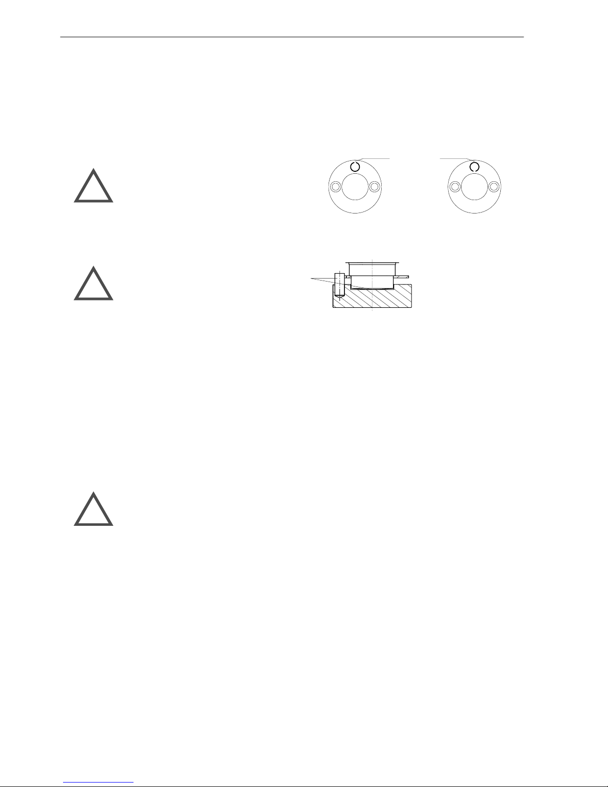
Jeder Wägezelle liegt in der Verpackung ein Spannstift bei, der in Verbindung mit der an der
Wägezelle angeschweißten Verdrehsicherung eine mögliche Mikrorotation des Aufnehmers und
damit eine evtl. Kabelbeschädigung verhindert. Dieser Spannstift ist mit einem Hammer in die am
Druckstück vorhandene Sack-Bohrung bis zum Aufsitzen des Stiftes einzuschlagen. Dabei die
offene Seite des Spannstiftes radial anordnen.
Anordnung des Spannstiftes zur Verdrehsicherung:
oder
Offene Seite radial anordnen !
!
Durch die Tiefe der Bohrung ergibt sich der korrekte Sitz des Stiftes. Je Wägezelle ist nur ein
Druckstück mit diesem Stift zu bestücken. Dieses muß unterhalb der Wägezelle montiert werden,
da der Spannstift dann in die vorhandene Aussparung der Verdrehsicherung eingreifen kann (siehe
Abmessungen = Kapitel 5). Die Bohrung am oberen Druckstück bleibt unbestückt.
Beachten Sie hierzu auch die speziellen Hinweise am Ende dieses Kapitels.
Die Stellflächen bzw. Fundamente unter dem unteren Druckstück (Lastausleitung) und ü ber dem
oberen Druckstück sollten möglichst eben und waagrecht sein. Die Druckstücke können bei
entsprechender Qualität der Flächen auch direkt auf Beton aufgestellt bzw. angeschraubt werden,
so daß keine weiteren Platten bereitgestellt werden müssen.
Die für Befestigung bzw. Fixierung erforderlichen Bohrungen sind vor der Montage an Brücke bzw.
Behälter und Fundament anzubringen. Die Abmessungen bei Verwendung von C16/ZOU44A bzw.
EPO3/50t + C16/EPU44A s ind aus den Maßzeichnungen in Kapitel 5 ersichtlich.
Page 4
4 Wägezelle • Load cell • Capteur de pesage C16i...
MA.C16i.0def -- 284.00--1053.4 -- Version a -- 05.04.2001
français (page 18 . .. 25) = en préparation
Der mechanische Einbau ist am Beispiel einer Brückenwaage im folgenden beschrieben und
sinnvollerweise in vorgeschlagener Reihenfolge vorzunehmen:
D Anheben der bereits mittig justierten Waagenbrücke an einer Stirnseite mittels geeigneten
Hebezeugen
D Montage der vorbereiteten Lasteinleitungsteile mit Spannstift zur Verdrehsicherung unten und
ohne Spannstift oben; das untere Druckstück ist so auszurichten, daß der Spannstift in die
Richtung zeigt, in die später der Kabelausgang und das Typenschild weisen soll, wird aber noch
nicht entgültig fixiert.
Anordnung des Spannstiftes zur Verdrehsicherung:
oder
Offene Seite radial anordnen !
!
D Zum Schutz vor Verschleiß, Verschmutzung und Korrosion sind obere und untere
Lasteinleitungsteile in der Lastaufnahme und der Spannstift sowie die Verdrehsicherung an der
Wägezelle mit reichlich Fett zu versehen, das mit den Wägezellen mitgeliefert wird.
Druckstücke und Spannstifte fetten:
!
D Fixierung der unteren Druckstücke mittels Spannscheibe bei Verwendung von EPO3/50t bzw.
Excenterscheiben bei Verwendung von C16/EPU44A oder C16/ZOU44A. Bei Verwendung des
HBM-Montagesatzes 2-9290.0070 (auch enthalten in 1-C16/EPU44A und C16/ZOU44A) ist das
Gummischlauchstück zur Abdichtung und zum Schutz der unteren Berührungsfläche Wägezelle
/ Druckstück mittels der beiliegenden Schlauchschelle am Wägezellengehäuse zu befestigen.
D Nun die Wägezellen in das untere Druckstück mit kreisender Bewegung so einsetzen, daß der
Spannstift am Druckstück in die Aussparung der Verdrehsicherung eingreift.
D Jetzt die Waagenbrücke soweit vorsichtig absenken und dabei die oberen Lasteinleitungen der
Wägezellen in die Lastaufnahme der oberen Druckstücke einführen, daß die Wägezellen gerade
noch unbelastetsindund senkrecht ausgerichtet werdenkönnen. Dies kann durchVerschieben
des unteren Druckstückes bei gelockerten Excenterscheiben geschehen. Die lotrechte
Einbaulage der Wägezelle ist am einfachsten mit einer geeigneten Prismenlibelle zu überprüfen,
die am zylindrischen Gehäuserohr angelegt werden kann. Danach die Brücke absenken und an
der anderen Stirnseite analog verfahren.
Wägezellen senkrecht ausrichten !
!
D Nach dem gesamten Einbau nochmals bei frei schwingender Brücke die lotrechte Einbaulage
aller Wägezellen kontrollieren und ggf. bei angehobener Brücke korrigieren. Eine exakte
Montage ist die beste Vorraussetzung für gute Meßergebnisse und geringste Eckenabweichung!
D Ist die endgültige senkrechte Ausrichtung der Wägezelle erreicht, werden die Excenterscheiben
gegen das Druckstück gedreht und durch Anziehen der Befestigungsschrauben fixiert.
Page 5

5Wägezelle • Load cell • Capteur de pesage C16i...
MA.C16i.0def -- 284.00--1053.4 -- Version a -- 05.04.2001
français (page 18 ... 25) = en préparation
Bei sehr großen Stützabständen der Wägezellen oder bei Wägebrücken mit größerer Durchbiegung
kann es durch die bei Belastung bedingten Abrollbewegungen der Wägezelle zu
Meßwertabweichungen kommen. Unterstützt wird diese Abrollbewegung durch seitliches
Auswandern der oberen Lasteinleitungspunkte der Wägezellen unter Last, wenn die Kontaktzone
zwischen Druckstück und Wägezelle weit unterhalb der biegeneutralen Faser der Wägebrücke liegt.
Um in diesen Fällen die auftretenden Abweichungen zu minimieren, können die Wägezellen mit
leichter Schrägstellung bis max. 1° nach innen angestellt montiert werden.
Biegeneutrale Faser
Unbelastet
Biegeneutrale Faser
Lage in unbelastetem Zustand
Belastet
Alternativ ist auch ein einseitiges Unterlegen von dünnen Blechen (ca. 0.5mm dick) unter die
Druckstücke an den angegebenen Stellen möglich.
Unterlegbleche
Konstruktiv kann diesem Effekt dadurch begegnet werden, daß die Auflagerpunkte an der
Wägebrücke soweit als möglich nach oben, in Richtung biegeneutraler Faser verlegt werden.
Wichtiger Hinweis:
D Vor dem ersten Belasten (Befahren) der Brücke mittels Fahrzeug, unbedingt die Anschläge so
einstellen, daß die zulässigen Schrägstellungen der Wägezellen bzw. s eitlichen Verschiebungen
der Lasteinleitungen nicht überschritten werden (siehe Abmessungen = Kapitel 5)! Ansonsten
kann es zur Beschädigung von Wägezellen oder Lasteinleitungen kommen.
Seitliche Anschläge
der Waagenplattform
einstellen:
!
Page 6

6 Wägezelle • Load cell • Capteur de pesage C16i...
MA.C16i.0def -- 284.00--1053.4 -- Version a -- 05.04.2001
français (page 18 ... 25) = en préparation
Spezielle Hinweise
Die Wägezellen C16 sind durch Laserschweißung metallisch gekapselt und aus nichtrostenden
Werkstoffen gefertigt. Damit wird die Schutzart IP68 nach EN 60529 (IEC 529) unter den
angegebenen Prüfbedingungen erreicht (siehe Technische Daten).
Grundsätzlich ist eine Reinigung der Wägezellen durch Dampfstrahlen möglich. Hierbei sind jedoch
die in EN 60 529 unter Schutzart IP69K genannten Bedingungen wie max. Druck, Temperatur usw.
zu beachten.
Bei Verwendung von HBM-Einbauteilen EPO3/50t + C16/EPU44A oder C16/ZOU44A kann die
integrierte Verdrehsicherung genutzt werden, wie in Kapitel 2 (Montage) beschrieben. Falls
kundenseitig hergestellte Einbauteile verwendet werden, stellt HBM Zeichnungen bereit, die Lage
und Montage der Verdrehsicherung zeigen. Hierbei ist insbesondere darauf zu achten, daß die
angegebenen Toleranzen für die Lage des Spannstiftes eingehalten w erden, damit eine
Beschädigung der Wägezellen ausgeschlossen wird.
Nur bei Ausführung nach HBM-Vorschrift gilt die HBM-Gewährleistung auf das Produkt.
Der Zubehörsatz Druckstücke C16/ZOU44A kann als kostengünstige Alternative auch mit
Wägezellen bis Nennlast 60t verwendet werden. Die je Wägezelle auftretende Höchstlast darf in
diesem Fall aber 40t nicht überschreiten.
Page 7

7Wägezelle • Load cell • Capteur de pesage C16i...
MA.C16i.0def -- 284.00--1053.4 -- Version a -- 05.04.2001
français (page 18 ... 25) = en préparation
3 Elektrischer Anschluß
Legen Sie bitte das Anschlußkabel der Wägezelle so, daß eventuell am Kabel entstehendes
Kondenswasser oder Feuchtigkeit abtropfen kann. Es darf nicht zur Wägezelle geleitet werden.
Außerdem ist dafür zu sorgen, daß keine Feuchtigkeit am offenen Kabelende eindringen kann.
Weiterhin das Kabel so verlegen, daß eine Beschädigung des Kabelmantels z. B. durch mögliche
Scheuerstellen aufgrund der Eigenbewegung der Wägezellen verhindert wird. An der
Kabeleinführung der Wägezelle ermöglicht ein Anschlußstutzen (∅10) die Montage eines
Kabel-Schutzschlauches mit NW10.
Elektrische und magnetische Felder verursachen oft eine Einkopplung von Störspannungen in den
Meßkreis.
Deshalb:
D Verwenden Sie nur abgeschirmte kapazitätsarme Meßkabel (HBM-Kabel erfüllen diese
Bedingungen)
D Legen Sie die Meßkabel nicht parallel zu Stromkabeln, insbesondere zu Starkstrom- und
Steuerleitungen. Falls dies nicht möglich ist, schützen Sie die Meßkabel, z. B. durch
Stahlpanzerrohre
D Meiden Sie Streufelder von Trafos, Motoren und Schützen
3.1 Busverschaltung mehrerer Wägezellen
Die Busverschaltung mehrerer Wägezellen erfolgt durch Verbinden der gleichfarbigen Aderenden
des Anschlußkabels. HBM empfiehlt hierfür die Verwendung eines Klemmenkastens ohne
Vorwiderstände (z.B. VKK2--6).
Kabelbelegung
UB
GND
RB (RX+)
RA (RX--)
TB (TX+)
TA ( T X - -)
weiß
rot
grau
grün
schwarz
blau
GNDUBRB (RX+)
RA (RX--)
TB (TX+)
TA (TX - -)
weiß
rot
grau
grün
schwarz
blau
GNDUBRB (RX+)
RA (RX--)
TB (TX+)
TA (TX - -)
Converter
(SC232/422A)
PC
C16i ... C16i ...
RS--232
RS--485 / 4--Draht BUS
Page 8

8 Wägezelle • Load cell • Capteur de pesage C16i...
MA.C16i.0def -- 284.00--1053.4 -- Version a -- 05.04.2001
français (page 18 ... 25) = en préparation
3.2 Externe Spannungsversorgung
Die Wägezelle hat einen digitalen Ausgang mit RS--485 (4-- Draht) Schnittstelle. Zur
Spannungsversorgung wird eine externe DC--Speisespannung benötigt.
Netzteilauswahl für C16i...:
Vorgehensweise zur Auswahl eines geeigneten (Stecker--) Netzteiles zur Versorgung des
Schnittstellenkonverters und der angeschlossenen C16i.. :
1. Feststellen der erforderlichen Kabellänge zwischen Netzteil und Klemmenkasten anhand der
Gegebenheiten vor Ort.
2. Stromverbrauch in Abhängigkeit der Anzahl der verwendeten Wägezellen aus der
untenstehenden Tabelle ablesen.
3. Kabelquerschnitt in betreffender Zeile so auswählen, daß die erforderliche Kabellänge realisiert
werden kann. Mit Nennspannung 15VDC sind immer längere Kabel oder kleinere
Aderquerschnitte realisierbar als mit 12VDC.
4. Spannung und Mindeststrom für erforderliches (Stecker--) Netzteil ablesen. Das Netzteil sollte
elektronisch geregelt sein.
Beispiel: 6 Wägezellen benötigen ca. 370mA (entspricht dem erforderlichen Mindeststrom des
Netzteiles), die erf. Kabellänge sei 100m. Dies kann bei 15VDC mit Kabelquerschnitt 0,14mm
2
realisiert werden. Bei 12VDC muß mindestens 0,25mm2gewählt werden.
Tabelle zur Stromversorgung (bei Verwendung des HBM-- Schnittstellenkonverters SC232/422A
mit Eigenverbrauch von ca. 70mA):
Maximale Kabellänge
zwischen Konverter und Klemmenkasten
Anzahl
Summe
Strom--
Nennspannung 12VDC Nennspannung 15VDC
Wägezelle
n
verbrauch
*
Aderquerschnitt Aderquerschnitt
0.14mm20.25mm20,5mm20,14mm20,25mm20,5mm
2
1 120 mA 352 m 500 m 500 m 500 m 500 m 500 m
2 170 mA 176 m 314 m 500 m 296 m 500 m 500 m
3 220 mA 117 m 210 m 419 m 197 m 352 m 500 m
4 270 mA 88 m 157 m 314 m 148 m 264 m 500 m
6 370 mA 59 m 105 m 210 m 100 m 176 m 352 m
8 470 mA 44 m 79 m 157 m 74 m 132 m 264 m
10 570 mA 35 m 63 m 126 m 59 m 106 m 211 m
12 670 mA 29 m 52 m 105 m 49 m 88 m 176 m
16 870 mA 22 m 39 m 79 m 37 m 66 m 132 m
* incl. HBM--Schnittstellenkonverter SC232/422A
Hinweis:
Das mit dem HBM--Schnittstellenkonverter SC232/422A mitgelieferte Steckernetzteil liefert
12VDC/700mA und ist damit zur Spannungsversorgung von max. 12x C16i geeignet.
3.3 Befehlssatz C16i...
Bitte fordern Sie hierzu bei Bedarf die separate Dokumentation über die Elektronik AD104* an!
* Dokumentation in deutscher oder englischer Sprache verfügbar
Page 9

9Wägezelle • Load cell • Capteur de pesage C16i...
MA.C16i.0def -- 284.00--1053.4 -- Version a -- 05.04.2001
français (page 18 ... 25) = en préparation
4 Technische Daten
Typ C16i D1 C16i C3
Nennlast (E
max
) 20t 30t 40t 60t 20t 30t 40t 60t
Genauigkeitsklasse nach OIML R60
Anzahl der Teilungswerte (n
LC
)
D1 (0.0330%)
1000
C3 (0.0180%)
3000
Mindestteilungswert der Wägezelle
(v
min
)
%
v. E
max
0.0200 0.0100 0.0083
Mindestteilungswert der Waage
(e
min
) nach EN 45 501
[... WZ = max. Anzahl an Wägezellen]
kg -- -- -- --
5
[6 WZ]
10
[10 WZ]
10
[10 WZ]
10
[6 WZ]
20
[10 WZ]
10
[4 WZ]
20
[10 WZ]
Nennkennwert (Cn) digit 1 000 000
Kennwerttoleranz % ≤±0.0100
Temperaturkoeffizient
des Kennwertes (TK
C
)
1)
%v.
≤±0.0250
1)
≤±0.0080
1)
Temperaturkoeffizient
des Nullsignals (TK
0
)
Cn/
10K
≤±0.0285 ≤±0.0140
≤±
0.0116
Relative Umkehrspanne (dhy)
1)
≤±0.0330
1)
≤±0.0170
1)
Linearitätsabweichung (d
lin
)
1)
%v.
≤±0.0300
1)
≤±0.0180
1)
Belastungskriechen (dcr)
über 30 min.
C
n
≤±0.0330 ≤±0.0167
Referenzspeisespannung (U
ref
) 12
Nennbereich der
Versorgungsspannug (B
U
)
V (DC)
7...15
2)
Stromaufnahme mA 50
2)
Auflösung Bit 20 (bei 1Hz)
Messrate /sec 100|50|25|12|6|3|2|1
Filtermode 0
8 ... 0.05 (Tiefpass)
Filtermode 1
H
z
8 ... 3 (Tiefpass)
Asynchrones Interface RS--485 / 4--Draht (Kabellänge bis 500m)
Baudrate Baud 1200 ... 38400
Busteilnehmer max. 32
Nennbereich der
Umgebungstemperatur (B
T
)
--10 ... +40
Gebrauchstemperaturbereich (Btu)
°C
--20 ... +70
Lagerungstemperaturbereich (Btl) --50 ... +85
Grenzlast (EL) 150
Bruchlast (Ed)
> 350
Relative zulässige Schwing-beanspruchung (F
srel
)
(Schwingbreite nach DIN 50100)
%
v. E
max
70
Nennmeßweg bei E
max(snom
), ca. mm 0.65 0.75 0.85 1.22 0.65 0.75 0.85 1.22
Gewicht (G) mit Kabel, ca. kg 2.2 2.4 3.0 3.8 2.2 2.4 3.0 3.8
Schutzart nach EN60529 (IEC529)
IP68 (Prüfbedingungen 1m Wassersäule/100h)
IP69K (Wasser bei Hochdruck, Dampfstrahlreinigung)
Material: Meßkörper + Gehäuse
Kabeleinführung
Dichtung
Kabelmantel
nichtrostender Stahl
nichtrostender Stahl
Neoprene
thermoplastisches Elastomer
1)
Die Werte für Linearitätsabweichung (d
lin
), Relative Umkehrspanne (dhy) und Temperaturkoeffizient des Kennwertes (TKC)
sind Richtwerte. Die Summe dieser Werte liegt innerhalb der Summenfehlergrenze für p
LC
= 0.8 nach OIML R60.
2)
Tabelle zur Stromversorgung auf Seite 8 beachten !
Page 10

10 Wägezelle • Load cell • Capteur de pesage C16i...
MA.C16i.0def -- 284.00--1053.4 -- Version a -- 05.04.2001
français (page 18 ... 25) = en préparation
Contents
Page
1 Safety instructions 10..........................................................
2 Mounting 11..................................................................
3 Connection 15................................................................
4 Technical data 17.............................................................
5 Dimensions and Mounting accessories 26........................................
Scope of supply:
-- Pendle load cell with connection cable
-- Dowel pin for rotation stop device
-- Plastic bag with grease
-- Mounting instructions
Mounting Accessories (optional):
Mounting Variation 1:
-- C16/ZOU44A thrust pieces (stainless steel) for above and below (1 Set = 2 pcs.),for use with
C16.../≤60t up to a max. load per load cell of 40 tons, incl. mounting set 2-9290.0070 (3 excentric
washers, 90mm flexible tube, tube clip)
Mounting Variation 2:
-- EPO3/50t thrust piece for above, incl. spanner
-- C16/EPU44A thrust piece for below, incl. mounting set 2-9290.0070 (3 excentric washers,
90mm flexible tube, tube clip)
1 Safety instructions
The load cells can be used as machine components. Please note that in these cases, in order to
achieve high sensitivity, the load cells have not been designed with the safety factors normally
applied in machine design.
Where a fracture might involve damage to property and injuries to persons, appropriate security
measures (e.g. antifall guard) must be taken by the user (observe the relevant accident protection
regulations).
Take into account the maximum limit loads given in the Technical data. The technical data for the load
cells applies within the specified load limits only.
The electronic system processing the measurement signal must be designed such that no
consequential damage is caused by the failure of the measurement signal.
Page 11

11Wägezelle • Load cell • Capteur de pesage C16i...
MA.C16i.0def -- 284.00--1053.4 -- Version a -- 05.04.2001
français (page 18 ... 25) = en préparation
2 Mounting
General hints
D Please handle the load cell carefully.
D Use appropriate lifting gear when mounting the weighing device.
D Do not overload the load cell, not even for a short time (e.g. due to unevenly distributed supporting
loads).
D If required, use supporting elements (dummies) of the same height for alignment purposes.
The C16 is a pendle load cell designed to automatically restore the mounting construction to a stable
initial position in the case of a lateral displacement of the load introduction (= skewing of the load cell).
The maximum permissible lateral displacement or skewing (refer to Dimensions = Chapter 5) must
not be exceeded, otherwise the load cells or load introduction parts might be damaged. The easiest
and most common solution for this problem are the appropriate stops on the mounting construction
(weighing platform) which must be carefully adjusted within the specified values.
With the C16i, we recommend the use of EPO3/50t + C16/EPU44A or C16/ZOU44A mounting
accessories from HBM, because they permit easy mounting. The rotation stop device welded onto
the load cells and the dowel pin provided are also suitable for this model type (refer to Dimensions
= Chapter 5).
Preparation work for mounting:
When using EPO3/50t + C16/EPU44A or C16/ZOU44A to introduce and carry off the load, the
following preparations have to be made:
A dowel pin is enclosed in the packing for every load cell. This dowel pin and the rotation stop welded
onto the load cell prevent a potential transducer microrotation, thus preventing the cable from being
damaged. Use a hammer to drive in the dowel pin until it rests in the load introduction part’s pocket
bore. Radially position the open side of the dowel pin.
Position of rotation stop dowel pin:
or
Radially position open side !
!
The bore depth ensures correct fitting of the pin. Only one load introduction part per load cell must
be equipped with this pin. This load introduction part must be mounted below the load cell to enable
the dowel pin to engage into the rotation stop recess (refer to Dimensions = Chapter 5). No pin must
be introduced into the bore on the upper load introduction part.
Please also refer to and comply with the special notes at the end of this chapter.
The areas or foundations below the lower load introduction part (for carrying off the load) and above
the upper load introduction part should be as even and level as possible. With areas complying with
these quality requirements, it is also possible to install or screw--fasten the load introduction parts
directly onto concrete so that no additional plates are needed.
Practically drill the required borings for securing and fixing on the weighbridge resp. tank and base
plate before you mount the weighing platform. The dimensions for use with EPO3/50t + C16/EPU44A
or C16/ZOU44A are as shown in the dimensioned drawings in chapter 5.
Page 12

12 Wägezelle • Load cell • Capteur de pesage C16i...
MA.C16i.0def -- 284.00--1053.4 -- Version a -- 05.04.2001
français (page 18 ... 25) = en préparation
Below, we use a weighbridge as an example for the mechanical installation. We recommend
that you proceed as follows:
D Use appropriate lifting gear to lift one face of the weighbridge that has already been centred.
D Prepare the load introduction parts a nd mount the part with the rotation stop dowel pin below and
the load introduction part without the dowel pin above. The lower load introduction part must be
aligned such that the dowel pin points in the direction in which, later on, the cable outlet and the
type plate are to be point, although do not yet finally fix it.
Position of rotation stop dowel pin:
or
Radially position open side !
!
D Use a sufficient amount of the g rease provided with the load cells to protect from wear, tear, dirt
and corrosion the upper and lower load introduction parts in the load carrying element, the dowel
pin and the rotation stop on the load cell.
Grease load introduction parts and dowel pins:
!
D Fix the lower load introduction parts with a spanning washer when using EPO3/50t or eccentric
washers when using C16/EPU44A or C16/ZOU44A. If HBM’s C16 mounting kit is used (order no.
2--9290.0070, also included in 1--C16/EPU44A and C16/ZOU44A), fasten the sealing rubber
tubing for protecting the contact between load cell and lower load introduction part to the load cell
housing with the tube clip included in the scope of supply.
D Now insert the load cells by rotating them into the lower load introduction part such that the dowel
pin engages into the rotation stop recess.
D Now let down the weighbridge carefully such that there is just no load on the load cells and that
they can be aligned perpendicularly. At the same time, introduce the load cells’ upper load
introduction parts into the upper load carrying element. For this purpose, you can move the lower
load introduction element with the eccentric washers loosened. We recommend that you use an
appropriate prism level to check the load cell’s perpendicular mounting position by holding it
against the cylindrical housing tube. Then let down the bridge and proceed in the same way for
the other face.
Align load cells vertically !
!
D After finishing the mounting procedure, once again check the perpendicular mounting position for
all the load cells, with the bridge swinging free and if required, lift the bridge to correct the position.
Exact mounting is an important condition for accurate measurements and minimum corner
deviation.
D Once the final perpendicular alignment of the load cell has been completed, turn the eccentric
washers towards the load introduction part and secure by tightening the fixing screws.
Page 13

13Wägezelle • Load cell • Capteur de pesage C16i...
MA.C16i.0def -- 284.00--1053.4 -- Version a -- 05.04.2001
français (page 18 ... 25) = en préparation
If there a re extremely long distances between the supports of the load cells or if the weighbridges
bend easily, the rolling movements of the load cell produced by a load can cause discrepancies in
the results. This rolling motion is assisted by a lateral drift of the upper load cell load introduction
points under load, if the contact zone between the load introduction part and the load cell is far below
the neutral bending axis of the weighbridge.
To minimise the discrepancies which occur in these cases, the load cells can be mounted at a slight
slant, set to a maximum of 1° inwards.
neutral bending axis
unloaded
neutral bending axis
initial state (unloaded)
loaded
Alternatively, thin steel plates (approx. 0.5mm thick) can be placed under one side, under the load
introduction parts, at the given points.
steel plates
Structurally, this effect can be met by shifting the bearing points on the weighbridge as far upward
as possible, towards the neutral bending axis.
Important note:
D Before loading the bridge for the first time by driving on it with a truck / vehicle, do in any case adjust
the lateral stops such that the load cells’ permissible skewings or lateral displacements of the load
introduction parts are not exceeded (refer to Dimensions = Chapter 5). Otherwise, the load cells
or load introduction parts might be damaged.
Adjust lateral stops of
the weighing platform:
!
Page 14

14 Wägezelle • Load cell • Capteur de pesage C16i...
MA.C16i.0def -- 284.00--1053.4 -- Version a -- 05.04.2001
français (page 18 ... 25) = en préparation
Special notes
Type C16 load cells are metal--clad by laser--welding and made from rustproof materials. Therefore
they comply with protection class IP68 according to EN 60 529 (IEC 529) under the stated test
conditions (see Technical data).
In general, the load cells permit steam jet cleaning. However, the conditions for max. pressure,
temperature, etc., stated in the EN 60 529 for protection class IP69K, must be observed.
When EPO3/50t + C16/EPU44A or C16/ZOU44A mounting parts from HBM are used, the integral
rotation stop device, described in chapter 2 (Mounting), can be used. With customised mounting
parts, HBM provides drawings showing the position and mounting of the rotation stop. In this case,
special attention must be paid to the observance of the tolerances stated for the dowel pin position,
to prevent the load cells from being damaged.
Only when the HBM specifications are followed will the HBM warranty for the product be valid.
The C16/ZOU44A load introduction parts accessory kit can be used as an economical alternative
for load cells with nominal loads up to 60t. In this case, however,the maximum load for each load
cell must not exceed 40t.
Page 15

15Wägezelle • Load cell • Capteur de pesage C16i...
MA.C16i.0def -- 284.00--1053.4 -- Version a -- 05.04.2001
français (page 18 ... 25) = en préparation
3 Connection
Position the load cell cable so that any condensation water or moisture forming on the cable can drip
off. It must not be routed to the load cell. In addition, make sure that no dampness can penetrate the
open end of the cable.
Furthermore, the cable must be placed such that the cable sheath suffers no damage, e.g. from
potential abrasion because of the load cell’s proper motion. A fitting (Ø 10) at the load cell cable entry
enables a protective cable conduit with nominal diameter 10mm to be mounted.
Electrical and magnetic fields often are the cause for the introduction of disturbing voltages into the
measuring circuit.
Therefore:
D Use shielded low-capacitance cable only (HBM cables meet these requirements).
D Do not lay the measuring cables in parallel to power cables, especially high-tension and control
lines. If this is not pssible, use steel conduits, for example, to protect and shield the measuring
cables.
D Avoid the stray fields resulting from transformers, motors and contactors.
3.1 Bus wiring of several load cells
The bus wiring of several load cells come into being by joining together the connection c ables’ core
ends with identical colours. HBM recommend the use of a junction box without dropping resistors
(e.g. VKK2--6).
Wiring code
UB
GND
RB (RX+)
RA (RX--)
TB (TX+)
TA ( T X - -)
white
red
grey
green
black
blue
GNDUBRB (RX+)
RA (RX--)
TB (TX+)
TA ( T X - -)
white
red
grey
green
black
blue
GNDUBRB (RX+)
RA (RX--)
TB (TX+)
TA ( T X - -)
Converter
(SC232/422A)
PC
C16i ... C16i ...
RS-232
RS-485 / 4 wire BUS
Page 16

16 Wägezelle • Load cell • Capteur de pesage C16i...
MA.C16i.0def -- 284.00--1053.4 -- Version a -- 05.04.2001
français (page 18 ... 25) = en préparation
3.2 External power supply
The load cell features a digital output with RS--485 (4--wire) interface. For the power supply an
external DC supply voltage is required.
Power supply unit selection for C16i...:
Procedure for selecting a suitable power supply unit to supply power to the interface converter and
the connected C16i load cells:
1. Determine the required cable length between power supply unit and junction box by examining
the actual on site situation.
2. In the table below, read off a ctual power consumption values in relation to the number of load cells
used.
3. Select cable cross--section in the relevant line such that the required cable length can be
implemented. With a 15VDC nominal voltage, it is always possible to implement longer cables or
smaller wire cross--sections than with a 12VDC rating.
4. Readoff voltage and minimum current for the (plug--in type) power supply unit required. The power
supply unit should be electronically controlled.
Example: 6 load cells require approx. 370mA (this corresponds to the minimum current required
by the power supply unit), the required cable length is to be 100m. At 15VDC, this can be
implemented with a cable cross--section of 0.14mm
2
. At 12VDC, a minimum cross--section of at least
0.25mm
2
needs to be selected.
Power supply t able (when using the HBM interface converter set SC232/422A with an internal
consumption of approx. 70mA):
Maximum cable length
between converter and junction box
Number of
Sum
(current con-
Nominal voltage 12VDC Nominal voltage 15VDC
loadcells
(
sumption)
*
Wire cross--section Wire cross --section
0.14mm20.25mm20,5mm20,14mm20,25mm20,5mm
2
1 120 mA 352 m 500 m 500 m 500 m 500 m 500 m
2 170 mA 176 m 314 m 500 m 296 m 500 m 500 m
3 220 mA 117 m 210 m 419 m 197 m 352 m 500 m
4 270 mA 88 m 157 m 314 m 148 m 264 m 500 m
6 370 mA 59 m 105 m 210 m 100 m 176 m 352 m
8 470 mA 44 m 79 m 157 m 74 m 132 m 264 m
10 570 mA 35 m 63 m 126 m 59 m 106 m 211 m
12 670 mA 29 m 52 m 105 m 49 m 88 m 176 m
16 870 mA 22 m 39 m 79 m 37 m 66 m 132 m
* incl. HBM interface converter set SC232/422A
Note:
The plug--in power supply unit , included in the scope of delivery for the HBM interface converter set
SC232/422A supplies 12VDC/700mA. So it can be used for operation with max. 12x C16i load cells.
3.3 Command set C16i...
Please request the separate documentation of our AD104* electronics, if required.
* Operating instructions available in German + English language versions
Page 17

17Wägezelle • Load cell • Capteur de pesage C16i...
MA.C16i.0def -- 284.00--1053.4 -- Version a -- 05.04.2001
français (page 18 ... 25) = en préparation
4 Technical data
Type C16i D1 C16i C3
Max. capactity (E
max
) 20t 30t 40t 60t 20t 30t 40t 60t
Accuracy class accord.toOIMLR60
Max. numbers of load cell
verification intervals (n
LC
)
D1 (0.0330%)
1000
C3 (0.0180%)
3000
Min. load cell verification interval
(v
min
)
%
of E
max
0.0200 0.0100 0.0083
Min. scale verification interval
(e
min
) according to EN 45 501
[... LC = max. Number of load cells]
kg -- -- -- --
5
[6 LC]
10
[10 LC]
10
[10 LC]
10
[6 LC]
20
[10 LC]
10
[4 LC]
20
[10 LC]
Sensitivity (Cn) digit 1000000
Sensitivity tolerance % ≤±0.0100
Temperature effect
on sensitivity (TK
C
)
1) %of
≤±0.0250
1)
≤±0.0080
1)
Temperature effect
on zero signal (TK
0
)
Cn/
10K
≤±0.0285 ≤±0.0140
≤±
0.0116
Hysteresis error (dhy)
1)
≤±0.0330
1)
≤±0.0170
1)
Non-Linearity (d
lin
)
1)
%of
≤±0.0300
1)
≤±0.0180
1)
Creep (dcr), 30 min.
C
n
≤±0.0330 ≤±0.0167
Reference excitation voltage (U
ref
) 12
Nominal range of
excitation voltage (B
U
)
V (DC)
7 ... 15
2)
Current consumption mA 50
2)
Resolution Bit 20 (at 1Hz)
Measuring rate /sec 100|50|25|12|6|3|2|1
Filter mode 0
8 ... 0.05 (Low pass f ilter)
Filter mode 1
H
z
8...3(Lowpassfilter)
Asynchrone Interface RS-485 / 4-wire (Cable lenght up to 500m)
Baudrate Baud 1200 ... 38400
Number of bus adresses max. 32
Nominal temperature range (BT) --10 ... +40 [14...104]
Service temperature range (Btu)
°C[°F]
--20 ... +70 [-4...158]
Storage temperature range (Btl)
[
]
--50 ... +85 [-58...185]
Limit load (EL) 150
Breaking load (Ed)
%
>350
Permissible dynamic load (F
srel
)
(vibration amplitude according to
DIN 50100)
of
E
max
70
Deflection at E
max(snom
), approx. mm 0.65 0.75 0.85 1.22 0.65 0.75 0.85 1.22
Weight (G) with cable, approx. kg 2.2 2.4 3.0 3.8 2.2 2.4 3.0 3.8
Protection class according to
EN60529 (IEC529)
IP68 (test conditions 100h at 1m water column)
IP69K (water at high pressure, steam jet cleaning)
Material: Meas. body + housing
Cable fitting
Sealing
Cable-sheath
stainless steel
stainless steel
neoprene
thermoplastical elastomer
1)
The data for Non--Linearity (d
lin
), Hysteresis error (dhy) and Temperature effect on sensitivity (TKC) are typical values. The
sum of these data meets the requirements for p
LC
= 0.8 according to OIML R60.
2)
Please refer to the table for the power supply on page 16!
Page 18

26 Wägezelle • Load cell • Capteur de pesage C16i...
MA.C16i.0def -- 284.00--1053.4 -- Version a -- 05.04.2001
français (page 18 ... 25) = en préparation
5 Abmessungen (mm) • Dimensions (mm) • Dimensions (mm)
2xM8
∅11
M10
∅85
∅64
∅44
∅76.1
R
C
B
A
EEK4
¡
£
¤
a
S
∅89
∅18
∅44
∅76.1
∅120
∅147
M10
20
C
4xM16
A
B
R
EEK4
©
¢
£
¤
¥
¥
120°
120°
3xM16
Ansicht von oben
Top view
Vuededessus
Einbauvariante 1:
(max. Belastung je Wägezelle = 40t)
Mounting Variation 1:
(max. load per load cell = 40t)
Variante de montage 1:
(charge maxi par peson = 40t)
C16i + C16/ZOU44A
Einbauvariante 2:
Mounting Variation 2:
Variante de montage 2:
C16i + EPO3/50t + C16/EPU44A
Befestigungsschraube um 90° gedreht gezeichnet
Fixing bolt, drawing turned by 90°
Vis de fixation représenté renversé de 90°
¡ C16/ZOU44A
© EPO3/50t
¢ C16/EPU44A
£ Anschlußstutzen Ø10 für Kabel-Schutzschlauch
Entry fitting Ø10 for protective cable conduit
Douille de raccordement Ø10 pour manch. passe -câbles
¤ Kabellänge (Standard): 20t + 30t = 12m / 40t + 60t = 20m
Cable length (standard): 20t + 30t = 12m / 40t + 60t = 20m
Longueur de câble (standard): 20t + 30t = 12m / 40t + 60t = 20m
¥ Spannstift (Verdrehsicherung), ∅10 x 30 im Lieferumfang der Wägezelle enthalten
Dowel pin (rotation stop), ∅10 x 30, enclosed in the packing of the load cell
Goupille (anti-rotation), ∅10 x 30
Page 19

27Wägezelle • Load cell • Capteur de pesage C16i...
MA.C16i.0def -- 284.00--1053.4 -- Version a -- 05.04.2001
français (page 18 ... 25) = en préparation
Einbauvariante 1 S Mounting Variation 1 SSSS Variante de montage 1
E
max
Druckstücke
oben + unten
(1 Satz = 2 Stück)
Thrust pieces
above + below
A
B C
R
(Kugel)
(Ball)
a2)S
3)
F
R
4)
(% der aufgebrachten Last)
(% of the applied load)
(en % de la charge appliquée)
C16 i
above+below
(1 set = 2 pcs.)
Pièces d’applique
en haut + en bas
(1 kit = 2 pièces)
ABC
(
)
(Rayon
de
sphère)
a
S
max
bei S
max
at S
max
àS
max
bei S = 1mm
at S = 1mm
àS=1mm
20t 200 150 123 130 5° 13 6.4 0.49
30t
200 150 123 160 5° 13 9.9 0.76
40t
C16/ZO
U44A
1
)
200 150 123 180 5° 13 12.2 0.94
60t 260 210 157 220 3° 11 5.7 0.52
Einbauvariante 2 S Mounting Variation 2 SSSS Variante de montage 2
E
max
Druckstücke
Thrust pieces
Pièces d’applique
A
B C
R
(Kugel)
(Ball)
a2)S
3)
F
R
4)
(% der aufgebrachten Last)
(% of the applied load)
(en % de la charge appliquée)
C16 i
oben
above
en haut
unten
below
en bas
ABC()
(Rayon
de
sphère)
a
S
max
bei S
max
at S
max
àS
max
bei S = 1mm
at S = 1mm
àS=1mm
20t 229 150 123 130 5° 13 6.4 0.49
30t
C16
/
229 150 123 160 5° 13 9.9 0.76
40t
EPO3/
50t
C16
/
EPU44A
229 150 123 180 5° 13 12.2 0.94
60t 289 210 157 220 3° 11 5.7 0.52
1)
Max. Belastung: 40t S Max. load: 40t S Charge maxi: 40t
2)
Max. zul. Schrägstellung S Max. permissible skewing S Oblicité maxi admise
3)
Max. zulässige seitliche Verschiebung der Lasteinleitung S Max. permissible lateral displacement of load introduction S
Décalage latéral maxi admis à l’introduction de la charge
4)
Rückstellkraft S Restoring force S Force de rappel
Einbauzubehör (optional) S Mounting accessories (optional) S Accessories optionels
C16/ZOU44A
Druckstücke (rostfrei) für oben und unten (1 Satz = 2 Stück), verwendbar mit C16.../≤60t bis zu einer max.
Belastung je Wägezelle von 40t, incl. Montagesatz 2-9290.0070 (3 Exzenterscheiben, 90mm-GummiSchlauchstück, Schlauchschelle)
Thrust pieces (stainless steel) for above and below (1 Set = 2 pcs.), for use with C16.../≤60t up to a maximum
load per load cell of 40 tons, incl. mounting set 2-9290.0070 (3 excentric washers, 90mm flexible tube, tube clip)
Pièces d’applique
EPO3/50t
Druckstück für oben, incl. Spannring
Thrust piece for above, incl. spanner
Pièce d’applique
C16/EPU44A
Druckstück für unten, incl. Montagesatz 2-9290.0070 (3 Exzenterscheiben, 90mm-Gummi-Schlauchstück,
Schlauchschelle)
Thrust piece for below, incl. mounting set 2-9290.0070 (3 excentric washers, 90mm flexible tube, tube clip)
Pièce d’applique
Page 20

28 Wägezelle • Load cell • Capteur de pesage C16i...
MA.C16i.0def -- 284.00--1053.4 -- Version a -- 05.04.2001
français (page 18 ... 25) = en préparation
Änderungen vorbehalten. Alle Angaben beschreiben unsere Produkte in allgemeiner Form. Sie stellen keine
Eigenschaftszusicherungen im Sinne des § 459, Abs. 2, BGB dar und begründen keine Haftung.
Modifications reserved. All details describe our products in general form. They are not to be understood as
express warranty and do not constitute any liability whatsoever.
Document non contractuel. Les caractéristiques indiquées ne décrivent nos produits que sous une forme
générale. Elles n’établissent aucune assurance formelle au terme de la loi et n’engagent pas notre responsabilité.
Hottinger Baldwin Messtechnik GmbH
Im Tiefen See 45, D--64293 Darmstadt, Germany
Tel.: +49 (0)6151 / 803 0; Fax: +49 (0)6151 / 803 9 100
www.hbm.com; e--mail: support@hbm.com
 Loading...