

Page 1

Operating instructions
Digital TransducerElectronics
AD104-R2,
AD104-R5
Page 2

Contents Page
Safety notes ..........................................................................................................................................2
1 Intended use................................................................................................................................3
2 Characteristic features ...............................................................................................................3
3 Mechanical construction ............................................................................................................4
4 Electrical construction ...............................................................................................................5
4.1 Function ...............................................................................................................................5
4.2 Signal processing ................................................................................................................6
Electrical connection ...........................................................................................................................8
5.1 Transducer Connection .....................................................................................................10
5.2 Serial Interface RS-232 (only AD104-R2).......................................................................... 10
5.3 Serial Interface RS485 (Bus mode with AD104-R5) .........................................................11
6 Command set ............................................................................................................................14
6.1 Command format ...............................................................................................................14
6.2 Answers to commands ......................................................................................................15
6.3 Output types for the measured values............................................................................... 15
6.4 Command overview ...........................................................................................................16
7 Individual descriptions of the commands .............................................................................. 17
7.1 Interface commands (asynchronous, serial)...................................................................... 17
7.2 Adjustment and scaling......................................................................................................27
7.3 Measuring ..........................................................................................................................35
7.4 Special functions................................................................................................................47
7.5 Error messages .................................................................................................................62
7.6 Bus termination for RS-485 version................................................................................... 63
7.7 Commands for Legal for trade Applications....................................................................... 64
7.8 Further commands.............................................................................................................67
7.9 Examples of communication.............................................................................................. 68
8 Technical data ...........................................................................................................................72
Page 3

2 / 75
Safety notes
• In the normal case the product causes no dangers, provided the notes and instructions for configuring,
installation, operation as intended and maintanance are complied with.
• The safety and accident prevention regulations applicable corresponding to the application must be
observed without fail.
• Installation and commissioning may be performed exclusively by qualified personell.
• Avoid the penetration of dirt and moisture into the interior of the unit when connecting the cables.
• When connecting the cables take measures against electrostatic discharges which can damage the
electronic unit.
• An extra low voltage with safe isolation from the mains is required for the power supply of the unit.
• When connecting additional devices, the safety regulations according to EN610101) must be complied with.
• Shielded cables are required for all connections. The shield must be connected flatly with ground at both
ends.
1) "Safety regulations for electrical measuring, control and laboratory equipment”
ba_aed104_8_e.doc
Page 4
AD104-R2, AD104-R5 3 / 75
1 Intended use
The digital sensor electronic units AD104 belong to the family of AED components which digitally condition and
network as bus-capable signals of mechanical measured value transducers. The objective of these components
is the digitization and conditioning of the measuring signals directly at the transducer. The AD104 and the
transducer (load cell) form a unit and cannot be replaced separately (transducer calibration of the measurement
chain with SZA/SFA is necessary).
As transducers, calibrated load cells or force transducers ( adjusted in TCZ,TCS, and zero point) can be used.
The measuring amplifier boards AD104 have different interface connections which are produced in the factory
by corresponding assembly:
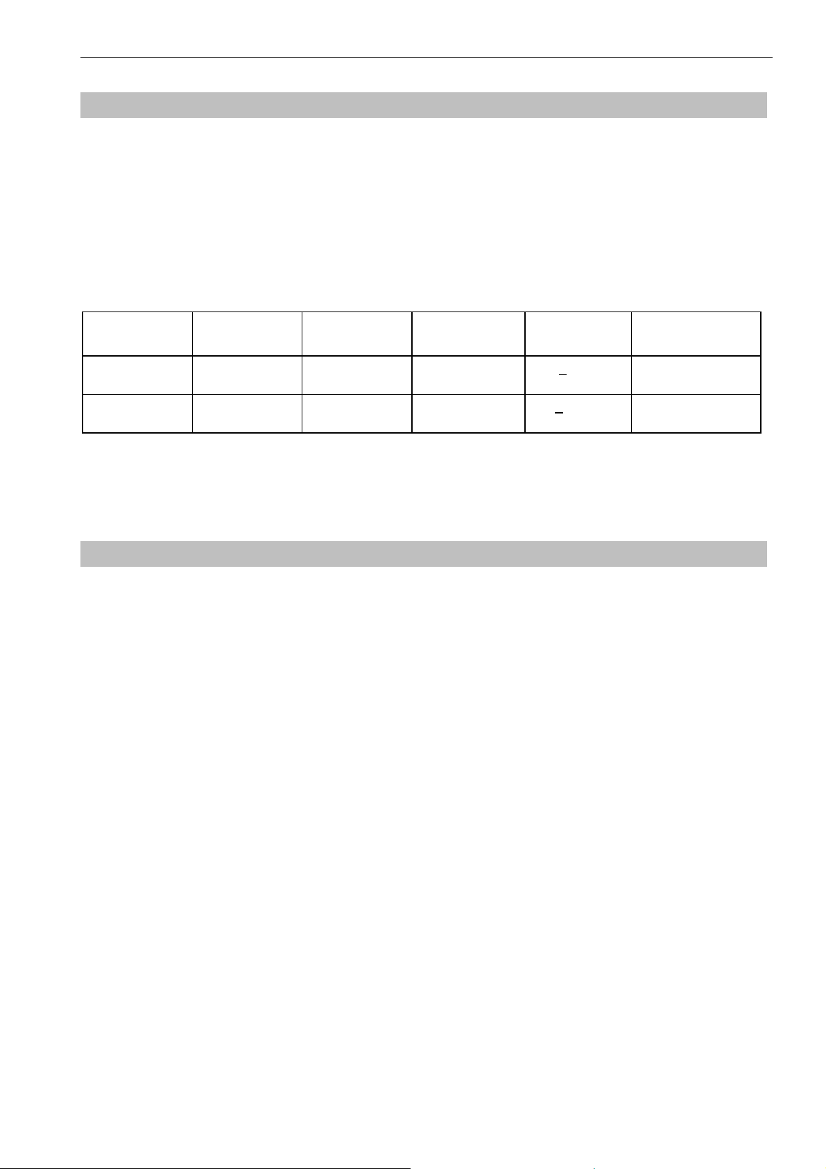
AD104-Type Interface Interface
Connect.
AD104-R2 Asynchronous,
serial
AD104-R5 Asynchronous,
serial
The transducer electronic units AD104 are also abbreviated with AED in the following text.
Old type: AD104-R4 Æ new type: is AD104-R5 with external trigger
New type: AD104-R2 with external trigger and RS232 interface.
RS-232 duplex no < 15m yes
RS-485 -4-wire,
full duplex
Bus mode Cable length external
Trigger
yes < 500m yes
2 Characteristic features
• Operating voltage 5.6V...15V DC
• 4 wire Interface for a full bridge sensor, nominal input range ±2 mV/V, maximal input range ±2.6 mV/V
• Serial interface RS-485 (bus mode) or through RS-232 interface (point - to - point mode)
• Digital filtering, choice of the output speed and scaling of the measured signal
• Separated calibration of transducer and application characteristic
• Storage of the parameters nonvolatile
• All settings are made through the serial interface
• Automatic zero tracking (1d/s, ±2%)
• Automatic intial zero setting (±2%...±20%)
• Trigger functions (level or external trigger)
ba_aed104_8_e.doc
Page 5
4 / 75
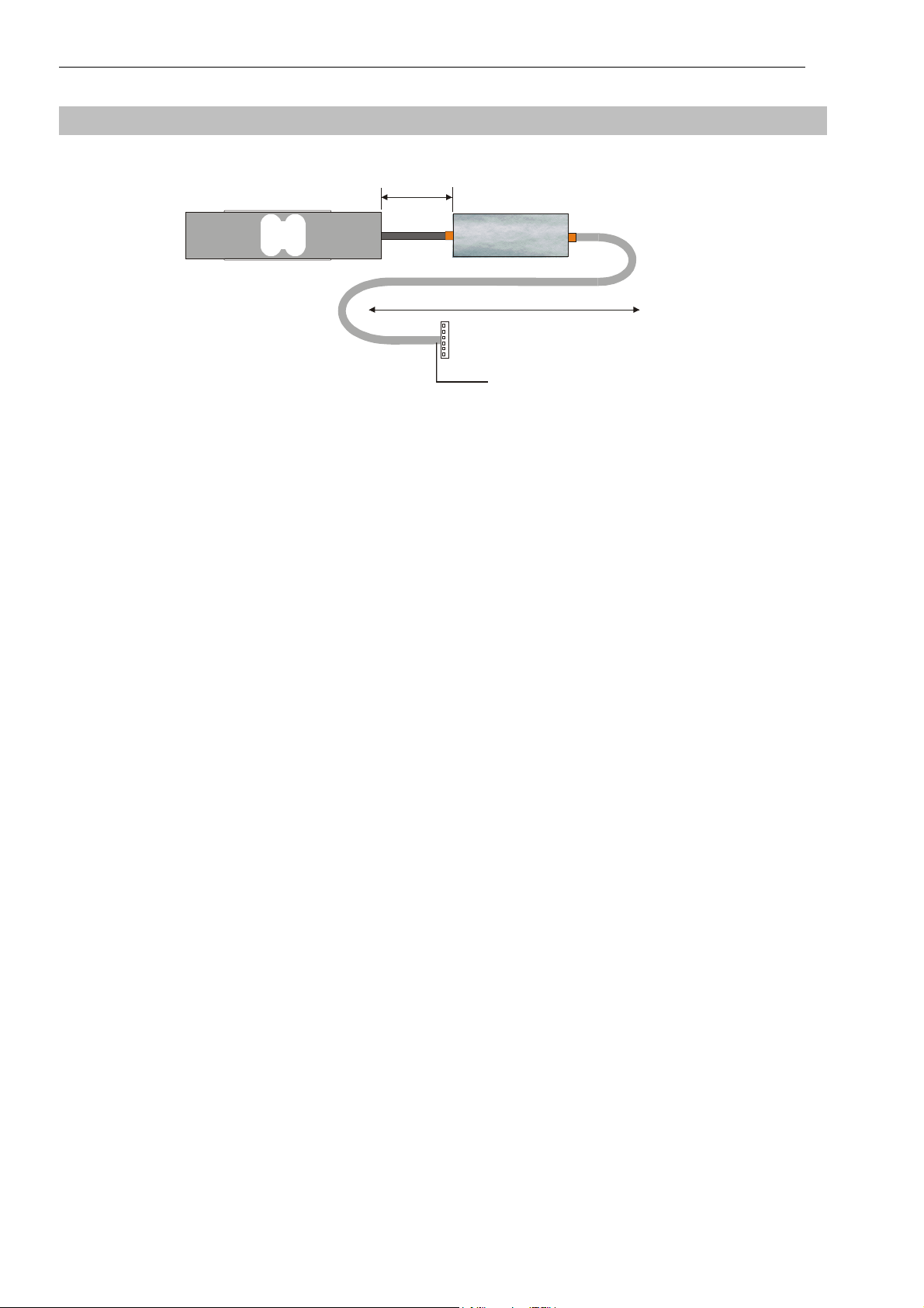
3 Mechanical construction
Load Cell
30 cm
AD104
1m...500m (depending on the type)
Pancon connector
female
Shield
Fig. 3.1: Example of a mechanical construction of a measuring chain (HBM)
The amplifier circuit board has to be placed in a shielded housing (EMC protection). The cable connections has
to be shielded leads.
With digital transducers (FIT, C16,...) the AD104 is build in the housing of the load cell. For digital measuring
chains the AD104 is included in a separate housing in the cable (degree of protection IP 40).
Warning: The AD104 board is not protected against electrostatic discharges. Appropriate safety
precautions must be taken for handling during assembly into the transducer.
ba_aed104_8_e.doc
Page 6
AD104-R2, AD104-R5 5 / 75
4 Electrical construction
The circuit of the digital transducer electronic unit consists essentially of the following functional groups:
• Transducer supply
• Amplifier
• Analog-digital converter (A/D)
• Microprocessor unit (µP)
• Parameter memory (EEPROM) protected against power failure
• Serial interface (RS232- 2 wire or RS485)
• Power supply
• Trigger input
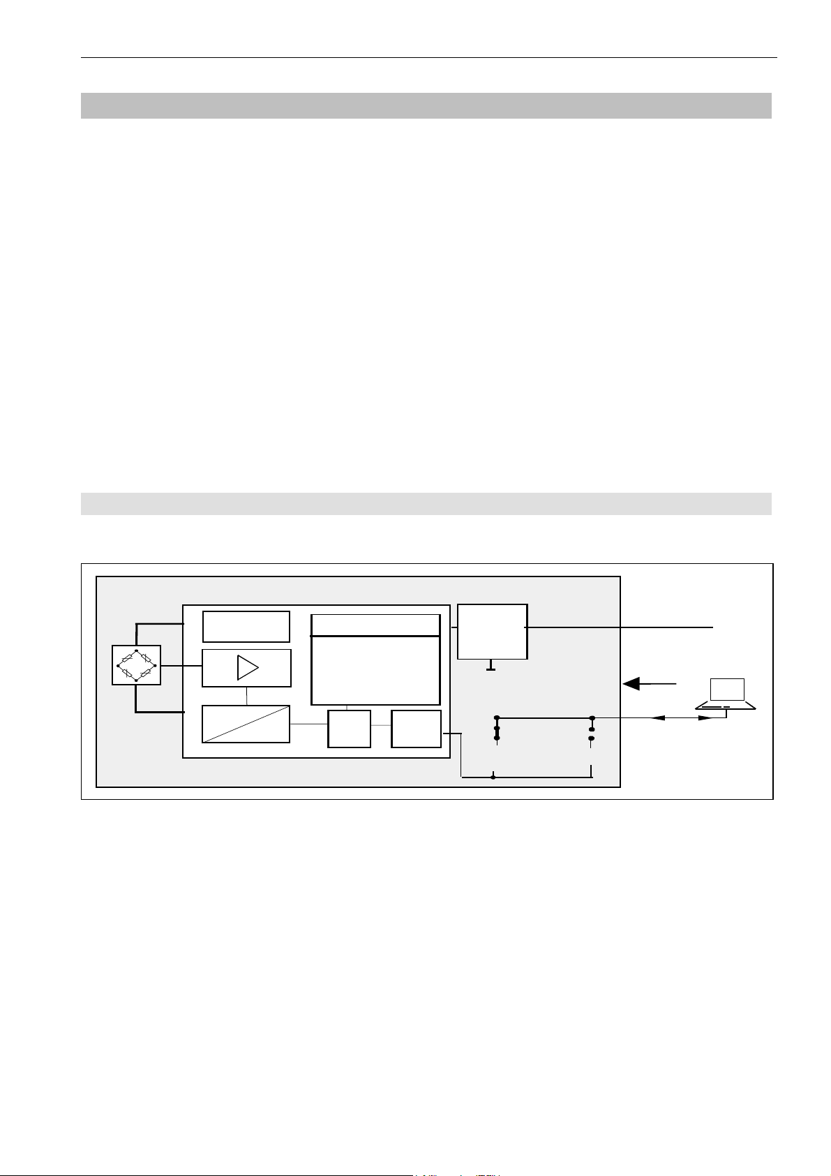
4.1 Function
Transducer
supply
A
D
Fig. 4.1: Measuring amplifier board AD104 block circuit diagram
EEPROM
Identifica tion.,
D igital filter, M e a s.
rate , S ca ling
Interface s etting
µP
Interfac e
Voltage
stabilize r
AD 104
RS-4854-wire
RS232
5.6 ...15V
< 60mA
Ext. Trigger
1200...38400 baud
The analog transducer signal is initially amplified, filtered and then converted into a digital value in the analogdigital converter. The digitized measuring signal is processed in the microprocessor. The conditioned signal is
then transmitted to a computer through the serial interface. All parameters can be stored in the EEPROM,
protected against power failures.
Power
unit
Com puter
ba_aed104_8_e.doc
Page 7
6 / 75
A
A
The transducer electronic unit is adjusted in the factory to the no-load and the nominal load of the transducer.
The electronic unit determines a factory characteristic through the commands SZA and SFA from these
measured values and images the measured values following later by means of this characteristic.
The following measured values are delivered according to output format (COF):
Output format Input signal Measured values
at
NOV = 0
Binary 2 characters
(Integer)
Binary 4 characters
(Long Integer)
ASCII 0...Nominal load 0 ... 1 000 000 Digit 0 ... NOV
You have the possibility of adapting the characteristic to your requirements (i.e. scale characteristic)
correspondingly with the parameter pair LDW and LWT and to standardize the measured values to the required
scaling value (e.g. 3000d) via the command NOV.
0...Nominal load 0 ... 20 000 Digit 0 ... NOV
0...Nominal load 0 ... 5 120 000 Digit 0 ... NOV
Measured
values at
NOV > 0
Delivery status
NOV=0
x
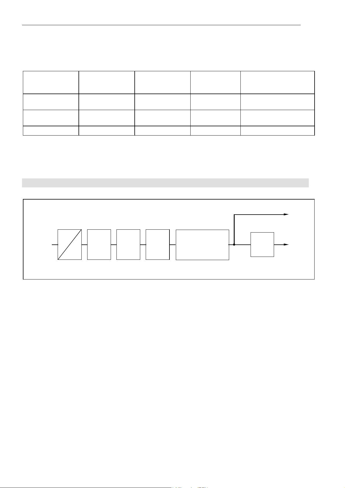
4.2 Signal processing
Gross
measured
value
Net
measured
value
Measuring
bridge
mpli-
fier
DC
FMD
ASF
Filter
ICR
Measur.
rate
SZA
SFA
Factory
scaling
LDW
NOV
LWT
User scaling,
Linearization
ZTR, ZSE
LIC
TAV, TAS
Net
TAR
Fig. 4.2.1: Signal flow diagram
After amplification and AD conversion, the signal is filtered by adjustable digital filters (command ASF). The
factory characteristic is determined with the aid of the commands SZA and SFA.
The measuring signal bandwidth (digital filter) is set with the command ASF. The measuring rate (number of
measurements per time unit) can be changed depending upon the filter bandwidth with the command ICR.
The user can set his own characteristic (commands LDW, LWT, NOV) without changing the factory calibration
(SZA/SFA). Furthermore, gross/net switch-over is available (command TAS). Using the command ZSE an
automatic switch-on zero setting can be activated. An automatic zero tracking function (ZTR) is also available.
For a linearization of the scale characteristic, the command (LIC) is available (with a polynomial of the 3rd
order). The polynomial parameters can be determined by means of a HBM PC program AED_LIC.
The current measured value is retrieved by the command MSV?. The format of the measured value (ASCII or
binary) is set by the command COF. An automatic measured value output can also be selected via the
command COF.
Two types of digital filters, which are switched over using the command FMD, are implemented in the AED. At
FMD0 filters lower than 1 Hz bandwidth are also available. In the filter mode FMD1, filters with fast transient
recovery are activated with high damping in the stop band. You will find detailed information in the chapter
‘Individual descriptions of the commands’.
ba_aed104_8_e.doc
Page 8
AD104-R2, AD104-R5 7 / 75
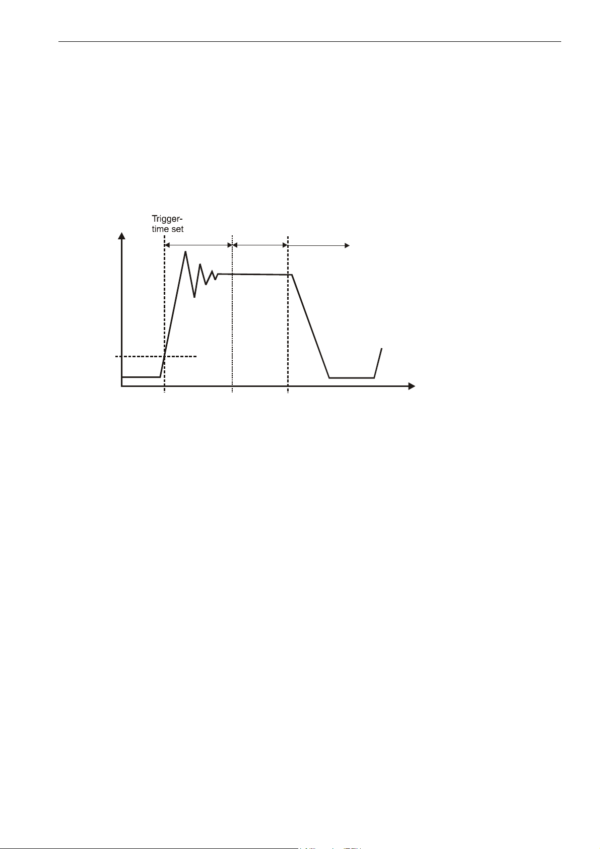
The AD104 comprises two trigger functions in order to support functions in packaging machines and
checkweigher:
• triggering by means of an adjustable level (gross and net measured value, for both types)
• external triggering by means of a trigger input
This special measuring mode is activated by means of the command TRC. The measured value determined is
output by means of the command MAV?. For this measuring mode, filter mode FMD1 should be set (fast
settling time).
The measuring speed depends on the preset stop time and the measuring period. The stop time should match
the fast transient recovery of the filter used (ASF).
Triggering
Weig ht
Trigger level
TRC- comm.
Parameter 3
if P2=0
(TRC-Command: Parameter 1=1)
Tr an s. Re cov.
time
TRC- command
Parameter 4
Measuring time
TRC- command
Parameter 5
Result in output memory
Time
Level triggering:
This measuring mode is suitable for weighing processes where the scale is relieved in between weighing
events.
The scale is in a no load condition. The material to be weighed will be placed on the scale, the trigger level is
exceeded, and stop time measurement starts. On expiry of this transient period, the actual weight will be
determined; and on expiry of this measuring period, the actual weight value will be stored in memory. The
weighing process can be restarted only once the weight value is again lower than the trigger level (place scale
in no load condition). In this measurement mode, weight determination does not need to be monitored by an
external computer at high speed. The output memory will contain an invalid value until a new measured value
has been created. After retrieving the contents of the measured value memory by means of the MAV?
command, this memory is reset to an invalid condition (invalid value < - 1600 000).
The periods (stop time and measurement period x 10ms at ICR0) and the trigger level can be freely set by
means of the command TRC. The trigger level will be on the user characteristic (NOV).
External trigger:
Both types support an external trigger instead of the limit value trigger. This trigger has a quiescent signal level
at 0V (=low) and uses the low/high edge to activate the measurement process.
The trigger flank starts the stop time measurement. On expiry of this transient period, the actual weight will be
determined over the measurement period, and the averaged actual weight value will be stored in memory. The
output memory will contain an invalid value until a new measured value has been created. After retrieving the
contents of the measured value memory by means of the MAV? command, this memory is reset to an invalid
condition. The periods (stop time and measurement period x 10ms at ICR0) and the trigger level can be freely
set by means of the command TRC. A renewed trigger flank will restart the measurement process. The scale
does not need to be placed into a no load condition.
During a measuring (waiting time + measuring time) a trigger signal is unvalid (no re-triggering). Within this
mode the parameter trigger level (P3) has no function.
ba_aed104_8_e.doc
Page 9
8 / 75
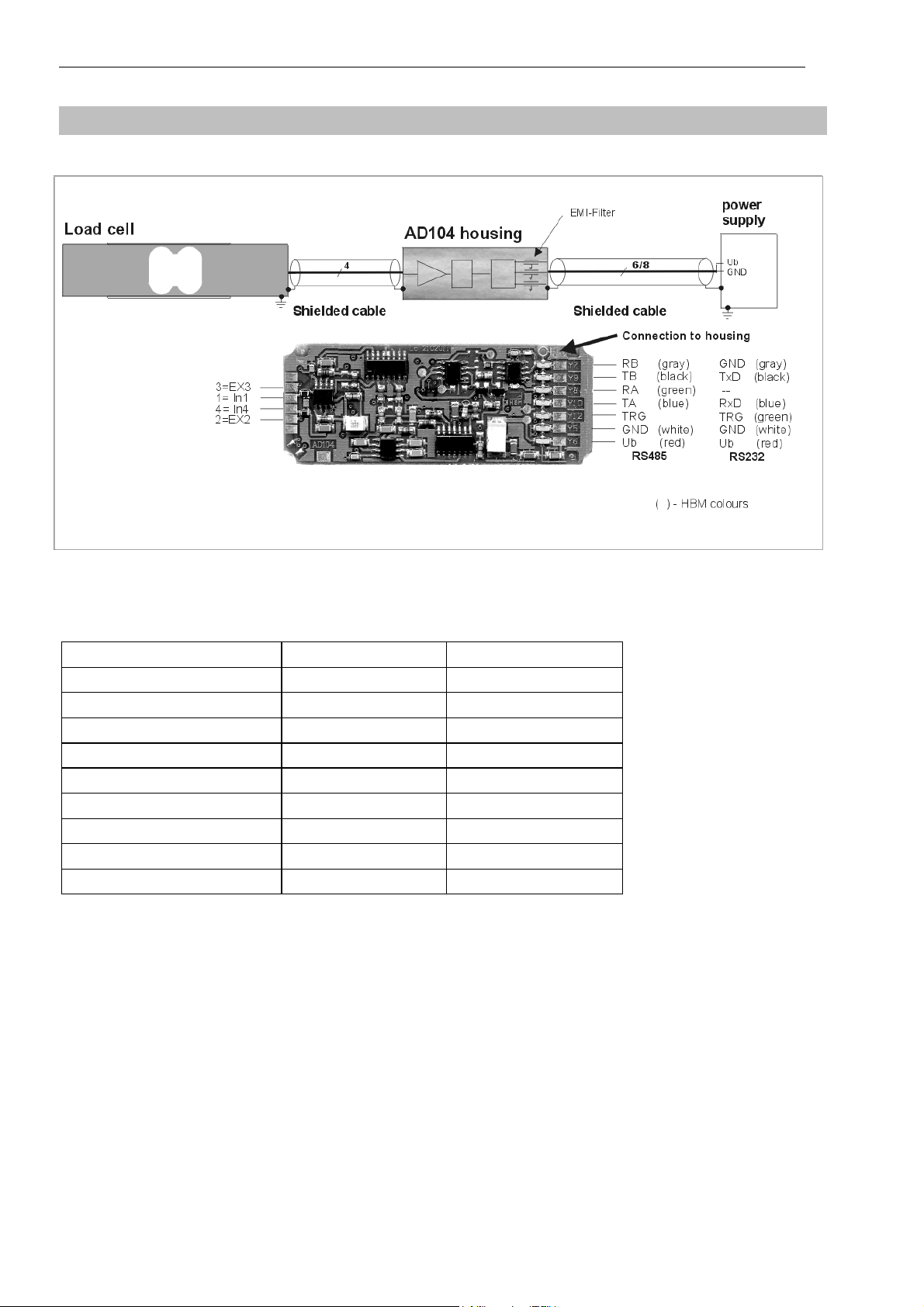
5 Electrical connection
(yellow)
Fig. 5: Connection schema of the PCB and shielding concept of a measuring chain
The connection to the PC is effected by means of a 6 / 8 pin Pancon connector. The following pin wirings result
at the connector according to the set interface (i.e. measuring chains of HBM):
AD104 type AD104-R5 AD104-R2
Pancon Connector Signals RS-485 Signals RS-232
1. red UB UB
2. white GND GND
3. blue TA RxD
4. green RA TRG
5. black TB TXD
6. grey RB GND
7. yellow TRG -
8. - -
- do not connect!
The measuring chain of HBM with AD104-R5 has a 8 wire shielded cable.
The measuring chain of HBM with AD104-R2 has a 6 wire shield
Explanation: UB Supply voltage (+ 5.6V...15V)
GND Ground
RA 4-wire connection AED receiver, line A (=RX-)
RB 4-wire connection AED receiver, line B (=RX+)
TA 4-wire connection AED transmitter, line A (=TX-)
TB 4-wire connection AED transmitter, line B (=TX+)
RxD Receiver data (UART, RS-232)
TxD Transmit data (UART, RS-232)
TRG External trigger signal
ed cable.
ba_aed104_8_e.doc
Page 10

AD104-R2, AD104-R5 9 / 75
Trigger input (electrical data):
High: 3.2V ... 5V
Low: 0V ... 0.8V
Input current: <2.5 mA
Important notes on EMC protection:
The PCB AD104 alone has no EMC protection. The EMC protection can be achieved in addition with a shielded
housing for the electronic and the use of shielded cable.
Mount the load cell onto a metallic carrier which is connected to the ground connection of the device, or shield
AD104 with the load cell and load introduction parts as a complete unit. The cable shield needs to be connected
with the measuring body of the loadcell and the housing of the AED.
The housing of the AED or the load cell has to be connected via the solder pad to the PCB (see Fig. 5,
‘connection to housing’). The AED unit itself is provided with a protective filter for all interfaces and supply lines.
The connection between load cell and electronics should be as short as possible. Depending on the bridge
resistance of the transducer used, line length, and line cross-section of the transducer connection cable, voltage
drops arise that lead to a reduction in the bridge supply voltage. Additionally, the voltage drop on the connection
cable is also temperature-dependent ( copper resistance ). The transducer output signal also changes in
proportion to the bridge supply voltage.
With the 4-wire circuit used, there still result measurement errors in conditions with changing temperatures,
caused by the temperature-dependent cable resistance and possibly also by transitory resistances in the
connectors.
When setting up a measurement chain (electronics outside the transducer) it should also be noted that the
AD104 uses a rectangular carrier frequency for bridge supply. Therefore, the cable length between AD104 and
the transducer is limited to 100 cm max. For high precision applications(>= 3000d), the length should be
reduced to 30cm (shielded cable, shield connection on the measuring body and on the shielded housing for
AD104).
ba_aed104_8_e.doc
Page 11
10 / 75
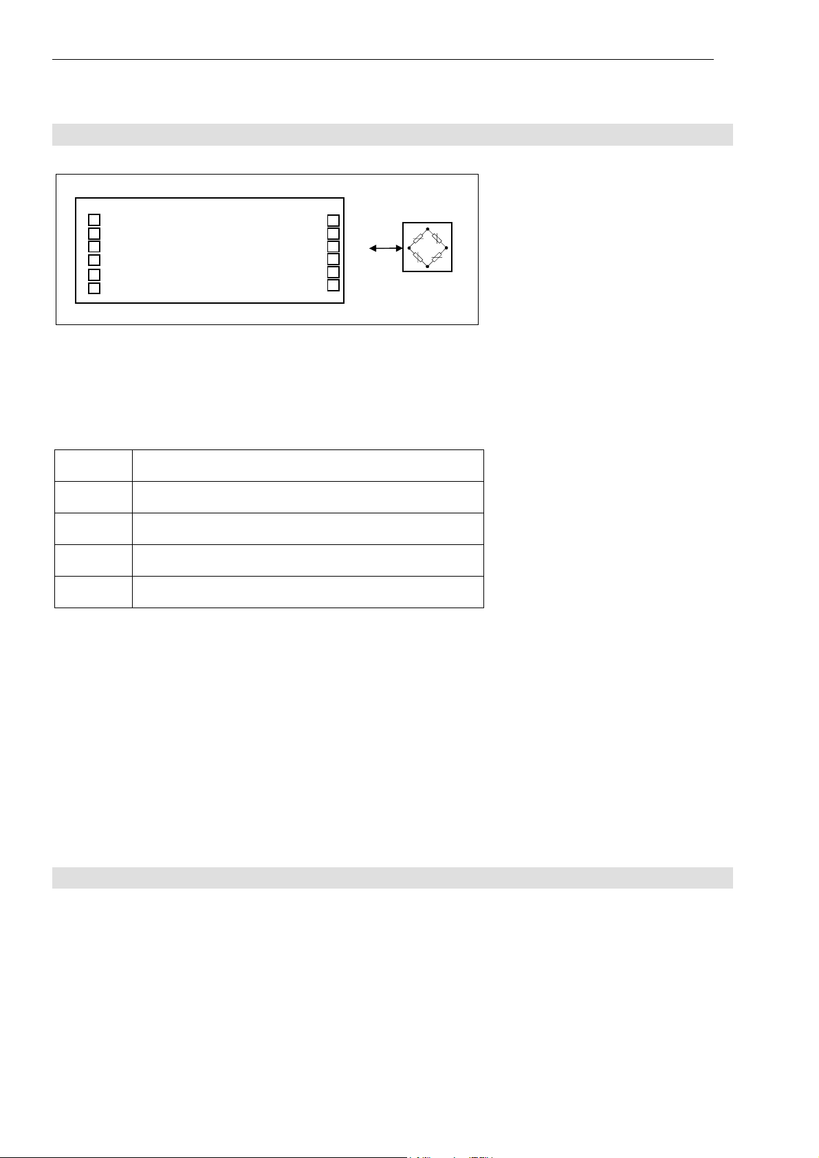
5.1 Transducer Connection
1-Ub
2-GND
3
4
5
6
Fig. 5.1: Transducer connection with the PCB (n.c. - not connected)
AD104
n.c.
U
IN4
IN1
U
n.c.
2
Br
4
3
Br
The AED amplifier is allready mounted with the transducer. A changing of the modules (AED or transducer) is
only allowed in HBM factory.
For the transducer connection a 4 core shielded cable has to be used.
Connection Pads for a full bridge:
Pad
Discription
UBr2 bridge excitation 2
IN4 amplifier input 4
IN1 amplifier input 1
UBr3 bridge excitation 3
Notes on cable length:
The connection between load cell and electronics should be as short as possible. Depending on the bridge
resistance of the transducer used, line length, and line cross-section of the transducer connection cable, voltage
drops arise that lead to a reduction in the bridge supply voltage. Additionally, the voltage drop on the connection
cable is also temperature-dependent ( copper resistance ). The transducer output signal also changes in
proportion to the bridge supply voltage.
With the 4-wire circuit used, there still result measurement errors in conditions with changing temperatures,
caused by the temperature-dependent cable resistance and possibly also by transitory resistances in the
connectors.
When setting up a measurement chain (electronics outside the transducer) it should also be noted that the
AD104 uses a rectangular carrier frequency for bridge supply. Therefore, the cable length between AD104 and
the transducer is limited to 100 cm max. For high precision applications(>= 3000d), the length should be
reduced to 30cm (shielded cable, shield connection on the measuring body and on the shielded housing for
AD104).
5.2 Serial Interface RS-232 (only AD104-R2)
The AD104-R2 is a version of the AD104 with an asynchronous, serial interface (UART interface with RS-232
line driver). This interface provide a point – to – point communication (no bus mode).
The baud rate of 1200...38400 baud can be selected for this interface. The following specifications result for the
transmission of one character:
Start bit: 1
Number of data bits: 8
Parity bit: none / even
Stop bit: 1
ba_aed104_8_e.doc
Page 12
AD104-R2, AD104-R5 11 / 75
Y
Y
Y
Y
Y
Y
Y
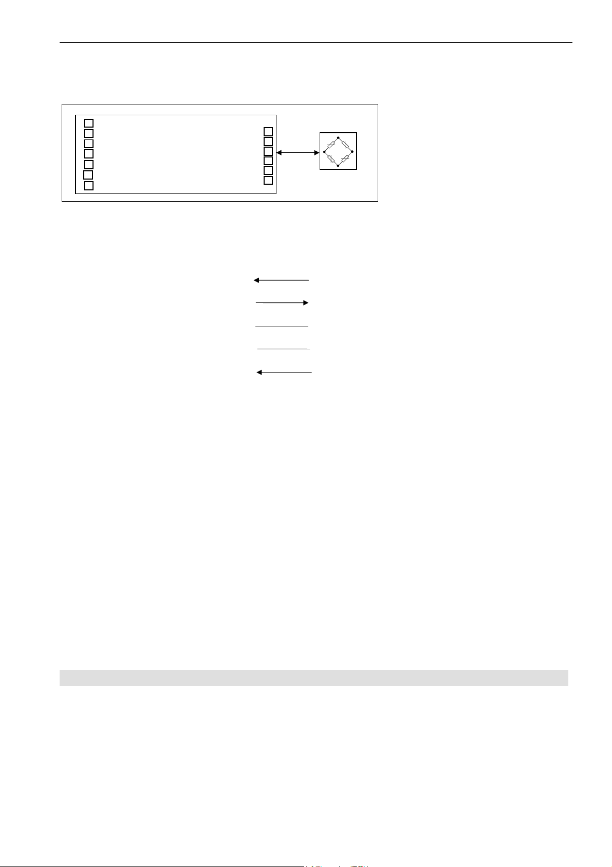
The connection is made through a six-core cable. The maximum cable length is 15 m. No bus mode is possible
in this type of communications (no bus driver).
6 -Ub
5 -GND
12-TRG
10-RxD
8 - n.c.
9 -TxD
7 - n.c.
Fig.5.2: Connections on the PCB (AD104-R2)
The connection scheme for the asynchronous interface results as follows:
AD104-R2 Master
Receiving line RxD TxD transmission line
Transmission line TxD RxD receiver line
AD104 – R2
Operating voltage U
B
supply voltage (5.6V..15VDC)
Ground GND GND Ground
Ext. trigger TRG external trigger signal
The levels on the RxD and TxD lines are RS-232 levels, whereby the quiescent-signal level is <-3V (Low).
External trigger signal:
Quiscent-signal level: TRG= 0V (Low)
Active measuring: TRG= Low-High edge (0V...5V)
If the external trigger is not used, the input remains open.
5.3 Serial Interface RS485 (Bus mode with AD104-R5)
Up to 32 AEDs can be connected to a common bus line through the RS-485 interface. The baud rate can be
selected between 1200 and 38400 baud in this version.
The following specification applies for the transmission of one character:
Start bit: 1
Number of data bits: 8
Parity bit: none / even
ba_aed104_8_e.doc
Page 13
12 / 75
Y
Y
Y
Y
Y
Y
Y
Stop bit:^ 1
6 -Ub
5 -GND
12-TRG
10-TA
8 -RA
9 -TB
7 -RB
Fig. 5.3.1: AD104-R5 for 4-wire bus mode (PCB connections)
1. Long lcable lengths (up to 500m) can be achieved with the aid of the RS485 bus drivers.
2. The bus mode of the AED is designed as master-slave configuration, whereby the AED implements a
slave. Thus all activities of the AED are initiated by the control computer. Each AED receives its own
communication address (00 ... 31) and can be activated through a select command Sii (ii= 00...31). A
broadcast command (S98) is implemented for certain cases of communication. This means that after such
a command, all AED execute the command of the master, but no AED answers. All commands of this
communication as well as corresponding examples are described in Chapter 7.
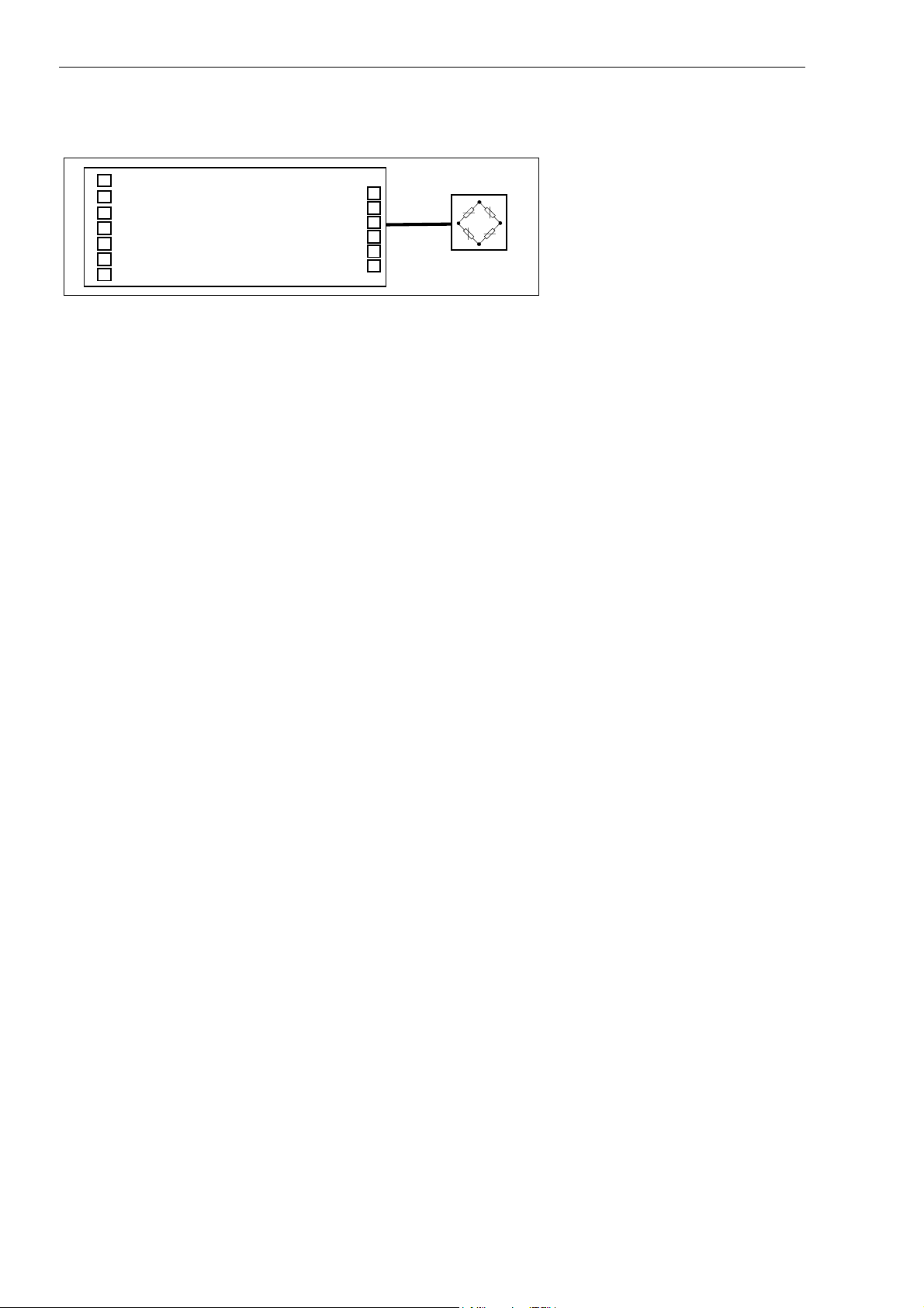
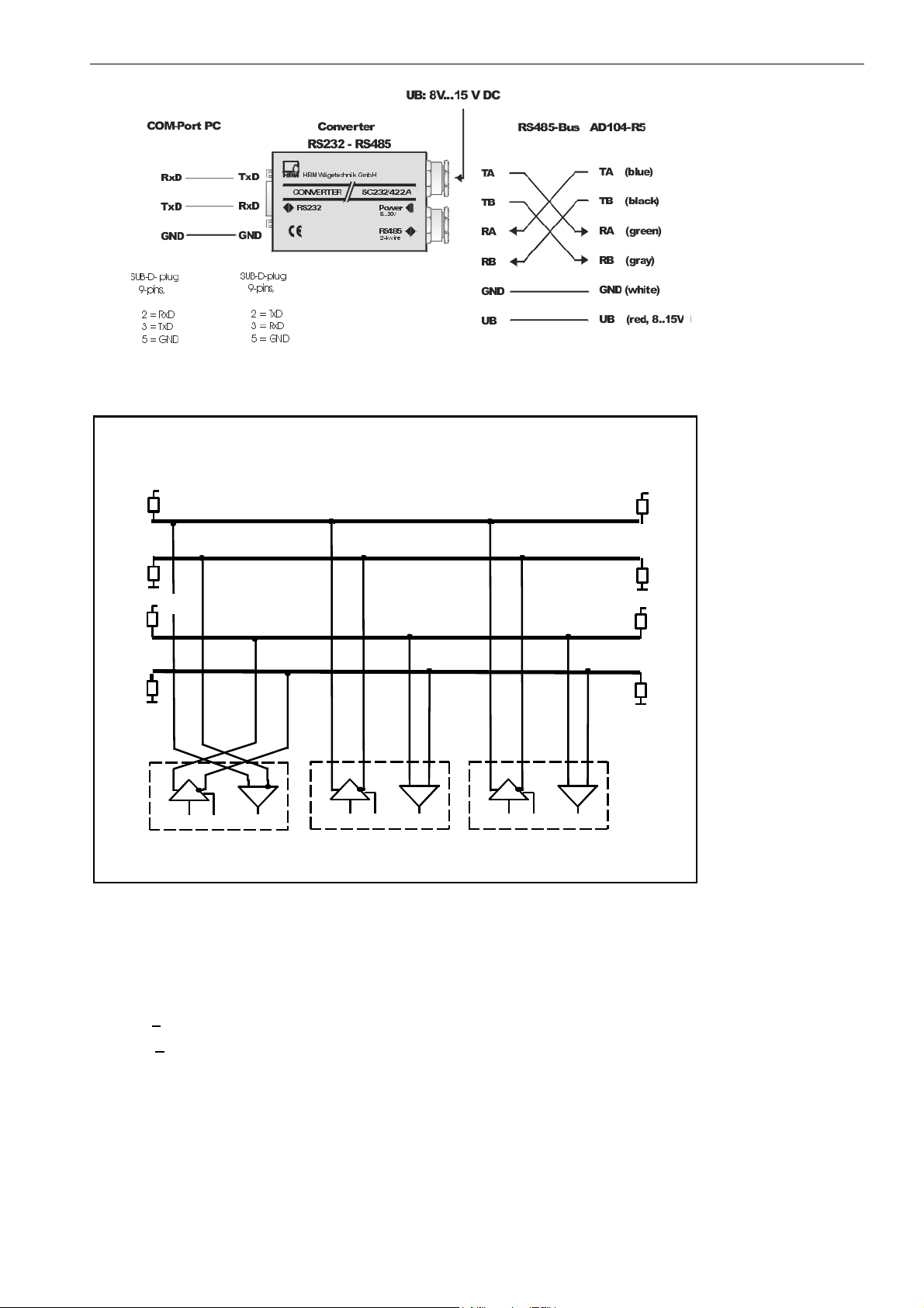
Figure 5.3.2 shows the connection of the bus to the RS232/RS485 Converter
(HBM Ordering-No. 1-SC232/422A).
AD104 – R5
Figure 5.3.3 shows the RS485 bus connection.
The terminating resistors of 500 ohms drawn in Figure 5.3.3 for the electrical function of the bus system are
important. These resistors protect the quiescent-signal levels for the receivers on the bus line. The master line
may be terminated with these resistors in this case only at the line ends. The master and the AED with the
address 31 should contain the terminating resistors for the local distribution of the bus connections shown in the
Figure. The AED contains these resistors already. These can be activated by the command STR1 (these
terminating resistors are switched off on factory delivery). These terminations may not be activated more than
twice in one bus.
The HBM interface converter also includes these terminators.
External trigger signal:
Quiscent-signal level: TRG= 0V (Low)
Active measuring: TRG= Low-High edge (0V...5V)
If the external trigger is not used, the input remains open.
ba_aed104_8_e.doc
Page 14
AD104-R2, AD104-R5 13 / 75
)
)
)
Fig: 5.3.2: Wiring of an AD104-R5 with an interface converter RS232/RS485
Line
Master line
4 - wire
termination
+5V
500
Ω
TB
TA
500
Ω
+5V
500
Ω
RB
RA
500
Ω
TB
TA RB RA
RT
RxDTxD on/off
TB TA RB RA
RT
TxD on/off
RxD
Computer=Master AED = Slave 00 Slave 31 . . .
TB TA RB RA
RT
TxD on/off
RxD
Line
termination
+5V
500
Ω
500
Ω
+5V
500
Ω
500
Ω
Fig: 5.3.3: Bus structure 4-wire bus (RS485)
The bus wiring is not to be allowed in star configuration. The leads of the slaves are not to be increased of 3m.
The best solution here: choin the main leads directly to the slaves.
The quiescent -signal level on the RS-485 master line results in the 4-wire mode at:
TB - TA > 0.35 V (quiescent -signal level due to the AED terminating resistors)
RB - RA > 0.35 V (quiescent -signal level due to the master terminating resistors)
Since the RS-485 is a differential bus interface, the quiescent-signal levels are also stated as a differential
voltage between the lines (and not related to ground). It must further be noted that this interface tolerates a
maximum common-mode range of +/-7V. If it is necessary, equipotential bonding should be established
between the bus subscribers through a separate line. The cable shield should not be used for this equipotential
bonding.
The shield of the master line is connected with the shield of the AED housing (not with the supply ground).
ba_aed104_8_e.doc
Page 15

14 / 75
6 Command set
The commands can be classified roughly into:
• Interface commands (ADR, BDR, Sxx, TEX, COF, CSM)
• Commands for adjusting and scaling (SZA, SFA, LDW, LWT, NOV, LIC)
• Commands for the measuring mode (MSV, ASF, ICR, TAR, TAS, TAV, FMD, STP)
• Special commands (ZSE, ZTR, TDD, RES, DPW, SPW, IDN, STR, TRC, MAV)
• Command for legal for trade applications (LFT, TCR, CRC)
6.1 Command format
General notes:
The commands can be input in uppercase or lowercase type.
Each command has to be terminated by a termination character. This can be optionally a line feed (LF) or a
semicolon (;). If only a termination character is sent to the AED, then the input buffer of the AED is cleared.
The statements made in round brackets () in the commands are urgently necessary and must be entered.
Parameters in pointed brackets <> are optional and can also be dispensed with. The brackets themselves are
not entered. Text must be included in “ “.
With numerical entries, leading zeros are suppressed. Numbers can be entered either directly or in exponent
format, e.g. +12000lf or +
exponent must not be more than 10 characters in length.
Answers consist of ASCII characters and are terminated with CRLF. The binary character output is an
exception (see command MSV).
Each command consists of the command initials, the parameter(s) and the termination character.
1,2e4lf. The exponent e can be one- or two-digit, but a number including sign and
Command initials Parameters End character
Input ABC X,Y LF or ;
Output ABC? X,Y LF or ;
Example: MSV?20
20 measured values are output after this command.
All ASCII characters <=- 20
except for 11
(ctrl q) and 13H (ctrl s).
H
(blank) may stand between command initials, parameters and end character,
H
H: Hexadecimal.
ba_aed104_8_e.doc
Page 16

AD104-R2, AD104-R5 15 / 75
6.2 Answers to commands
Answers to inputs (exception COF64...COF79):
Answer End character
Correct input 0 (zero) CRLF
Faulty input ? CRLF
Exceptions: The commands RES, STP, S00 ... S99 deliver no answer.
The command BDR delivers the answer in the new baud rate.
An error flag is received through the command ESR.
Answers to output commands:
Correct command Parameter1, ... Parameter n, or measured values CRLF
Faulty command ? CRLF (error flag via command ESR )
6.3 Output types for the measured values
You can select two types of output and a data delimiter (command TEX).
Output type 1:
The measured values are output arranged beneath one another.
Measured value1 CRLF
Measured value2 CRLF
. . . . . . . .
Measured value n CRLF
Output type 2:
The measured values are output arranged next to one another.
Measured value1 (data delimiter) Measured value2 (data delimiter) ... Measured value n CRLF
The measured value query works with fixed output lengths
(see command COF):
Format command AED answer Number of bytes
COF0; msv?; yyyy CR LF (y- binary) 6
COF2; msv?; yy CR LF (y- binary) 4
COF3; msv?; xxxxxxxx CR LF (x- ASCII) 10
COF9; msv?; xxxxxxxx,xx,xxx CR LF (x- ASCII) 17
There is always a CRLF or the data delimiter defined by the command TEX as end identification of the
measured value output. However these characters must not be filtered out as end identification in the binary
output, since these characters can also be contained in the binary code of the measured value. Therefore only
counting the bytes helps in the binary output. The corresponding places after CR or LF or the data delimiter can
then be enquired for subsequent syntax testing.
Password protection:
The password protection of the AED comprises important settings for the characteristic of the scale
and its identification. Commands with password protection are activated only after the password is
entered. These commands are answered with “?“ without entry of the password through the command
SPW.
ba_aed104_8_e.doc
Page 17

16 / 75
6.4 Command overview
Command PW TDD 1 Function Page
ADR
ASF
BDR
COF
CRC
CSM
DPW
ENU
ESR
FMD
ICR
IDN
LDW
LFT
LIC
LWT
MAV
MSV
NOV
RES
S...
SFA
SPW
STP
STR
SZA
TAR
TAS
TAV
TDD1/2
TDD0
TEX
TCR
TRC
ZSE
ZTR
x Zero point, user characteristic 32
x Linearization 57
x Nominal value, user characteristic 33
x x Nominal value scaling 34
x Internal nominal value, factory characteristic 30
x Stop measured value output 29
x Factory setting 52
xAdress18
x Digital filter 40
x Baud rate 19
x Output format in MSV? 20
external checksum for legal for trade applic. 66
x checksum in MSV status 24
Define password 47
Dimensional unit 50
Status 62
x Filter mode 42
x Measuring rate 43
Identification of transducer type and serial number 51
x Legal for trade applications 64
Measured value, trigger function 58
Measured value output 36
Reset 49
Select of AED in bus operation 26
Password entry 48
Messwertausgabe stoppen 39
x Switch bus termination resistors on/off 63
Tare mode 44
x Gross/net switch-over 46
x Tare value 45
Store setting in EEPROM, read EEPROM 52
x Data delimiter for measured value output 25
Trade counter 65
x Trigger setting 59
x Initial zero setting 55
x Automatic zero tracking 56
TDD1 – stored with TDD1 command
PW – protected by password with commands DPW/SPW
The following commands result in no change to the AED setting:
ACL, ASS, CAL, COR, GRU (compatibility with other AED versions).
ba_aed104_8_e.doc
Page 18
AD104-R2, AD104-R5 17 / 75
7 Individual descriptions of the commands
7.1 Interface commands (asynchronous, serial)
Characteristic data of the interfaces
Start bit: 1
Word length: 8 bits
Parity: none / even
Stop bit: 1
Software handshake (XON / XOFF) is possible
Baud rate: 1200; 2400; 4800; 9600;19200; 38400 baud
The asynchronous interface of the AED is a serial interface, i.e. the data are transmitted bit for bit after one
another and asynchronously. Asynchronous means that the transmission works without a clock signal.
A start bit is set before each data byte. The bits of the word, a parity bit for the transmission protocol (optional)
and a stop bit then follow.
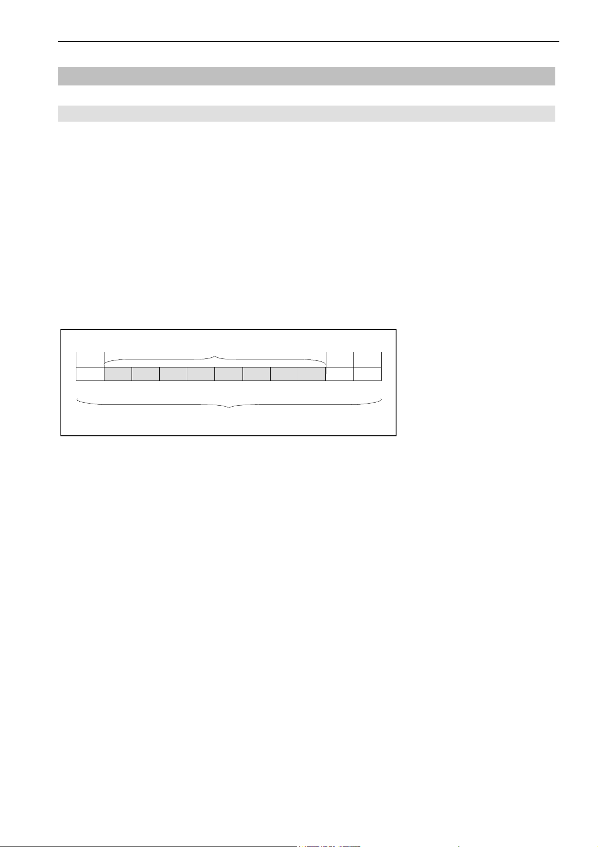
1 Bit Word length = 8 data bits 1 Bit 1 Bit
Start Parity Stop
1 character
Fig. 7.1.1: Composition of a character
Since the data are transmitted after one another, the transmission speed must agree with the reception speed.
The number of bits per second is called baud rate.
The exact baud rate of the receiver is synchronized with the start bit for each transmitted character. The data
bits which all have the same length then follow. After the stop bit is reached, the receiver goes into a ‘waiting
position’ until it is reactivated by the next start bit.
The number of characters per measured value depends upon the selected output format (COF command) and
can be 2 to 17 characters (see also COF command).
The interface must be configured to build up the communication between AED and computer. The following
commands are provided in the AED for this : ADR; BDR; COF; TEX; S..;
ba_aed104_8_e.doc
Page 19

18 / 75
Address
ADR
Range: 0...31
Factory setting: 31
Response time: <15ms
Parameters: 2
Password protection: none
Parameter protect.: with command TDD1
Input: ADR(new address),<"Serial No.">;
The serial number can also be stated optionally as 2nd parameter. The new address is then entered only for the
AED with the stated serial number. This makes it possible to change device addresses in the case of several
AEDs with the same address (initialization of the bus mode).
The serial number must be stated in “ “ as in the command IDN.
(device address)
Entry of the device address as decimal number 0...31.
Example: ADR25,"007" CRLF
Query: ADR?; 25CRLF (Example)
Effect: Output of the device address as decimal number 0...31
ba_aed104_8_e.doc
Page 20

AD104-R2, AD104-R5 19 / 75
Baud Rate
BDR
Baud rates: 1200, 2400, 4800, 9600, 19200, 38400 Baud
Factory setting: 9600 Baud and even parity
Response time: <15ms
Parameters: 1
Password protection: none
Parameter protect.: with command TDD1
Input: BDR <Baudrate>,<Parity>
Entry of the required baud rate as decimal number.
Possible baud rates are:
1200, 2400, 4800, 9600, 19200, 38400 Baud
Input or the requested parity:
0= without parity bit
1= with even parity bit
(Baud rate)
Important Note
The answer is given in the new setting (baud rate, parity). Communication is no longer possible initially after a
changed baud rate. The computer must also be changed over to the newly selected baud rate setting.So that
the baud rate remains changed permanently, it must be stored in the EEPROM with the command TDD1. This
procedure serves also as safeguard that no baud rates can be set in the AED which the remote station does not
support. If the newly entered baud rate is not stored, the AED reports after a reset or power On again in the
previously valid baud rate.
Query: BDR?;
Effect: Output of the set baud rate, Identification for parity bit
Example: BDR?; 9600,1 CRLF corresponds to 9600 baud, even parity
ba_aed104_8_e.doc
Page 21

20 / 75
Configurate Output Format
COF
Range: 0...255
Factory setting: 9
Response time: <15ms
Parameters: 1
Password protection: none
Parameter protect.: with command TDD1
Input: COF(0...255);
Input of the output format for measured value command MSV
The possible formats and the decimal number to be entered for them are listed in the following Table. The
measured value output refers here to the set nominal value of the AED (see command NOV).
Output at max. capacity NOV> 0 NOV= 0
2 Byte binary NOV value 20000
4 Byte binary NOV value 5120000
ASCII NOV value 1000000
(Ausgabeformat für die Messwertausgabe)
For the 2-bytes binary output, the NOV value must be < 30000, otherwise the measured value is output with
overflow or underflow (7fff H or 8000H). With NOV30000, the overload range is only still approx. 2700 digits.
Query: COF?;
Effect: Output of the selected output format as three-digit decimal number from 0...255
ba_aed104_8_e.doc
Page 22

AD104-R2, AD104-R5 21 / 75
COF formats:
The following combinations result on entry of COF0 to COF12:
• MSB = most significant byte
• LSB = least significant byte
In binary output, the sequence of the bytes MSB Æ LSB or LSB Æ MSB can be selected. In ASCII output, the
device address and/or measured value status information can be output in addition to the measured value.
Binary format:
Parameter Length Sequence of the measured value output
COF0
COF2
COF4
COF6
COF8
COF12
Measured value 4 Byte MSB before LSB LSB=0 (no Status)
Measured value 2 Byte MSB/LSB
Measured value 4 Byte LSB before MSB LSB=0 (no Status)
Measured value 2 Byte LSB/MSB
Measured value 4 Byte MSB before LSB LSB=Status/CRC
Measured value 4 Byte LSB before MSB LSB=Status/CRC
ASCII format:
In ASCII output, a freely selectable data delimiter is set between the parameters (see command TEX). crlf or the
selected data delimiter follows after the last parameter.
T = Data delimiter () = Number of characters
1st Parameter T 2nd Parameter T 3rd Parameter End character
COF1
COF3
COF5
COF7
COF9
COF11
Important Note
In bus mode, the output format must not be set to COF9.
Meas. value (8) T(1) Adress (2) — CRLF or T
Meas. value (8) — — CRLF or T
identical with COF1
identical with COF3
Meas. value (8) T(1) Adress (2) T(1) Status(3) CRLF or T
Meas. value (8) T(1) — — Status(3) CRLF or T
ba_aed104_8_e.doc
Page 23

22 / 75
Bus mode: COF16 to COF 28
If the decimal number 16 is added to the above stated output formats COF0...COF12, then the AED is switched
into the bus output mode. A measured value is output. The AED switches over to the partially active mode (each
new measured value is stored in the output buffer but not output). The measured value is output on the bus with
the select command S..;.
Example: 2 AED’s in bus operation
Command Effect
S98;
COF18;
ICR0;
MSV?0;
S01;
S02;
All AED are partially active (listening but not transmission)
Output in 2 byte binary output
Maximum measuring rate
Continuous measurement in AED
Read measured value from 1st AED, immediate output of current measured value, without
measuring time
Read measured value from 2nd AED, when response from first AED has been received
completely. Immediate output of current measured value, without measuring time
S01;
S02;
... ...
STP;
S01;
Binary measured value output without CRLF: COF32 to COF44
If the decimal number 32 is added to the above stated binary output formats COF0...COF12, the AED is
switched into the following output mode for the measured values.
In the binary measured value output, the end character CR LF is left out, so that only 2 or 4 characters per
measured value are output. This measure increases the output speed of the measured values.
Format Length Sequence of the measured value output
COF32
COF34
COF36
COF38
COF40
COF44
Read measured value from 1st AED, when response from second AED has been received
completely
Read measured value from 1st AED, when response from second AED has been received
completely
Stop measured value output
Poss. new setting for 1st AED
4 Byte MSB before LSB LSB=0 (no status)
2 Byte MSB before LSB
4 Byte LSB before MSB LSB=0 (no status)
2 Byte LSB before MSB
4 Byte MSB before LSB LSB=status/CRC
4 Byte LSB before MSB LSB=status/CRC
2-wire bus mode: COF64 ... COF76 (do not use for variants AD104-R2 and AD104-R5)
If the decimal number 64 is added to the above stated output formats COF0...COF12, then the AED is switched
into the 2-wire bus mode. This means that the AED answers no longer with “0“ or “?“ on command inputs. The
answer with the parameter or in the case of MSV? with the measured value occurs only for command enquiries
(e.g. ASF?). The command MSV?0; (continuous measured value transmission) may no longer be used in this
case since otherwise it is no longer possible to stop this output (apart from supply voltage off).
ba_aed104_8_e.doc
Page 24

AD104-R2, AD104-R5 23 / 75
Continuous output after power On: COF128 to COF 140
If the decimal number 128 is added to the above stated output formats COF0...COF12, then the AED is
switched into the continuous output mode. After the power On or RES command, the AED outputs the
measured values without MSV? request. The continuous output can be switched off with the command STP.
The setting is made with the following entries (COF≥128):
1. ... make necessary settings
2. ICRi; set measuring rate of the AED
3. COFx+128; the AED transmits measured values continuously,
time interval corresponding to ICR, x=0...12
4. STP; stop continuous transmission
5. TDD1; store protected against power failure
6. COFx+128; the AED transmits measured values continuously,
time interval corresponding to ICR.
The AED starts with the measured value output without separate request also after switching on the voltage.
These output formats have another special feature (depending on how triggering is set, command TRC):
Trigger deactivated: continuous automatic measured value output
Trigger activated: automatic measured value output only if a new measured value has been
created after triggering (MAV? output value).
Output speed of measured values:
The AD104 can output a maximum of 100 measured values per second. This data rate also depends upon the
baud rate (BDR), the data format of the measured value output and the set averaging (ICR).
Table 1 shows this relationship in the continuous measured value output (MSV?0):
Measured values/s 100 50 25 12 6 3 2 1
(ICR)
Time in ms 10 20 40 80 160 330 500 1000
Output format (COF) necessary baud rates for MSV0; (BDR)
Binary format
2 characters at COF2/COF6
Binary format
4 characters at COF0/COF4
ASCII format
Meas. value 10 characters at COF3
ASCII format
Meas. value + Adress
13 characters at COF1
ASCII format
Meas. value + Adress + status
17 characters at COF9
2400 1200 1200 1200 1200 1200 1200 1200
4800 2400 1200 1200 1200 1200 1200 1200
19200 9600 4800 2400 1200 1200 1200 1200
19200 9600 4800 2400 1200 1200 1200 1200
38400 19200 9600 4800 2400 1200 1200 1200
Note for the evaluation of the binary measured values:
The binary codes for CR and LF can occur inside the bytes representing the measured value in the measured
value output in binary format. Therefore the contents of the measured value output must not be tested for the
characters CR/LF in order possibly to check the end of the measured value transmission. Rather the number of
characters which are received should be registered for the binary output. The control characters CR/LF are also
appended to the measured value in the binary output (sole exception: MSV?0;).
ba_aed104_8_e.doc
Page 25

24 / 75
Checksum
CSM
Range: 0/1
Factory setting: 0
Response time: <15ms
Parameters: 1
Password protection: none
Parameter protect.: with command TDD1
Input: CSM(0/1);
Query: CSM?;
Effect: The adjusted fuction is given out as: (0/1).
The command checksum can be used to find out transmitting errors within 4 Byte binary output.
If CSM=0 the normal status will be transmitted (see MSV).
If CSM=1 in stead of the status a checksum will be transmitted in the binary output format COF8 and COF12
(+i∗16, i=0,1...7). The checksum is a EXOR over the 3 bytes of the measured value.
(Cheksum only in MSV binary status)
ba_aed104_8_e.doc
Page 26

AD104-R2, AD104-R5 25 / 75
Terminator Execution
TEX
Range: 0...255
Factory setting: 172
Response time: <15ms
Parameters: 1
Password protection: none
Parameter protect.: with command TDD1
Input: TEX(0...255);
The wanted data delimiter is input in decimal form as ASCII character (e.g. comma = 2C
TEX44; H: Hexadecimal, D: Decimal). Any ASCII character from 0...127
delimiter. The data delimiter is set between the parameters in the measured value output (see also commands
MSV and COF).
Example: TEX44;
Measuring value output: -0123456, 12, 000, -0123457, 12, 000, etc. (at COF9)
If the selected ASCII character is entered with an offset of 128
(above example: comma = 44
then the parameters of a measured value are separated by comma as before, but crlf is output at the end of the
measured value.
(Data delimiter between measured values)
(0...7FH) can be taken as data
D
+ 128 D = 172 D Æ entry TEX172;),
D
= 44 D Æ input
H
Example: TEX172;
This results in: -123456,12,000
-123457,12,000 etc.
Query: TEX?;
Effect: The set data delimiter is output as 3-digit decimal number (0...255).
ba_aed104_8_e.doc
Page 27

26 / 75
Select
S...
Range: 0...31, 98
Factory setting: —
Response time: <15ms
Parameters: 1
Password protection: none
Parameter protect.: no data to be protected
Input: S(00...31, 98); (only with semicolon, not with CRLF!)
The select command generates no answer. Several AEDs connected together to form a BUS can be addressed
individually or jointly with it. An AED is always active after reset or power On (except for COF>127) and must
therefore be addressed through the select command. A maximum of 32 addresses (00...31) can be allocated
through the command ADR.
Important Note
(Selection of AEDs in bus mode)
The command S.. alone generates no answer. The selected AED answers only together with a further
command. Except in the bus mode: COF16...COF28 (after MSV?0;).
Example: S00;
Command 1
Command 2...n
S01;
Command 1 etc.
The command S98; is provided for special functions (broadcast). In this case all AEDs connected to the bus are
addressed. All AEDs execute the following commands. No AED answers. This occurs as long as only one AED
is addressed through S00 ... S31 again.
A measured value query in the bus can be performed as follows:
1. All AED selected via command S98;.
2. Measured value query MSV?;, all AED form the measured value and places value after the integration
time (ICR) in the output buffer, but no AED transmits
3. Select AED with address 1 with command S01;. The AED with adress 01 outputs the measured value
4. Select AED with address 1 with command S02;. The AED with adress 02 outputs the measured value
etc.
ba_aed104_8_e.doc
Page 28

AD104-R2, AD104-R5 27 / 75
7.2 Adjustment and scaling
The commands described below serve for setting the factory characteristic as well as the user characteristic:
• Commands for adjusting the transducer characteristic: SZA, SFA
• Commands for adjusting the user characteristic: LDW, LWT
• Scaling of the measured values: NOV
Setting the characteristic
As delivered, the AED works initially with a factory characteristic SZA / SFA (range 0...2 mV/V). This
characteristic can be used for calibrating the the transducer characteristic. This characteristic should not be
changed. It has to be print ore stored to keep the data.
The user can adapt the AED characteristic to his requirements with the command pair LDW, LWT
(application or scale characteristic).
In the following, the balance of a measuring chain will be described with the balancing of a scale. This example
can also be used for other kinds of transducers.
Important Note
The characteristic commands LDW, LWT must be entered or executed in the sequence LDW , then LWT... The
input data are not computed until both parameters have been entered or measured in pairs The scaling must be
switched off when determining the characteristic (NOV0).
After the values for zeropoint and nominal value of the user characteristic have been measured or entered, the
range LDW Æ LWT (at NOV=0) is mapped to the following numerical ranges:
Output at nom. load (COF) NOV=0 NOV>0
2 Byte binary 20000 NOV value
4 Byte binary 5120000 NOV value
ASCII 1000000 NOV value
For the 2-bytes binary output, the NOV value must be < 30000, otherwise the measured value is output with
overflow or underflow (7fff H or 8000H ; H: Hexadecimal). With NOV30000, the overload range is only approx.
2700 digits.
ba_aed104_8_e.doc
Page 29

28 / 75
A
A
A
Set user characteristic with LDW, LWT
ction
Enter password
Load = 0, scale
Load = Nominal value, scale
Digit
1.000.000
COF3
700.000
100.000
1.000.000
COF3
I
0,2 2
pplication measuring range
Digit
Command string
SPW"AED";
LDW;
LWT;
II
1,4
Factory characteristic
Load
in mV
User characteristic
II
I
0,2
pplication measuring range
1,4
Fig. 7.7-1: Setting the user characteristic
Load
in mV
ba_aed104_8_e.doc
Page 30

AD104-R2, AD104-R5 29 / 75
Sensor Zero Adjust
SZA
Range: 0...1,599999e6
Factory setting: adjusted on unloaded transducer
Response time: <15ms...4.2s
Parameters: 1
Password protection: yes
Parameter protect.: after input of SFA
Input: SZA; (Response time: <4.2s)
Effect: Using this command, the transducer electronic system measures an input signal
Input: SZA<zero value>; (Response time: <15ms)
(Factory characteristic – zero point)
between ±2.5mV/V, stores the measured value as the zero point of the factory
characteristic, but only starts the calculation of the new characteristic after
entering the parameter for SFA.
Effect: Instead of causing the AED to measure the applied signal, the value is entered
here. The entered value is stored, but accounted for only after entry of the
parameter for SFA as the zero point of the factory characteristic.
Query: SZA?; (Response time <15ms)
Effect: The value used in the AED for calculating the factory characteristic for the zero
point is output in ±7 digits (e.g. -0000345crlf).
Important Note
Entry the command SZA and SFA ore execute. The data will be calculated if both parameters were given in
pairs ore been measured.
ba_aed104_8_e.doc
Page 31

30 / 75
Sensor Fullscale Adjust
SFA
Range: 0...1,599999e6
Factory setting: adjusted to nominal load of transducer
Response time: <15ms...4.2s
Parameters: 1 (0)
Password protection: yes
Data protect.: with input
Input: SFA; (Response time: <4,2s)
(Factory characteristic – fullscale value)
Effect: Using this command, the transducer electronic system measures an input signal
Input: SFA <fullscale value>; (Response time: <15ms)
Effect: Instead of causing the AED to measure the applied signal, here the value is
Query: SFA?; (Response time <15ms)
Effect: The value used in the AED for calculating the factory characteristic for the zero
Important Note
Entry the command SZA and SFA ore execute. The data will be calculated if both parameters were given in
pairs ore been measured.
Procedure for entering the factory characteristic:
1. Enter password by means of command SPW
between ±2.5mV/V, stores the measured value as the fullscale value of the
factory characteristic and calculates the new characteristic together with the
previously entered value for SZA.
entered directly as the fullscale value of the factory characteristic, stored and
used together with the previously entered value for SZA.
point is output in ±7 digits (e.g. -0915345CRLF).
2. Switch off the scaling withNOV 0; output (scaling off)
3. Deactivate user characteristic by means of LDW0; and LWT1000000;
4. Adjust the ASF filter such that a maximally quiescent display is effected
5. Transducer (not scale) without load, wait until standstill
6.
Determine measured value with MSV?; , note value1 for SZA
7. Load transducer (not scale) with nominal load, wait until standstill
8. Determine measured value with MSV?; , note value2 for SFA
9. Enter new characteristic with : SZA value1; subsequently SFA value2
10. Redetermine the user characteristic LDW/LWT
The points 3...8 are not applicable if the factory characteristic is entered anew using already known parameters.
ba_aed104_8_e.doc
Page 32

AD104-R2, AD104-R5 31 / 75
User settings:
The commands LDW and LWT work like the commands SZA and SFA . It is possible with these commands to
make a system-specific calibration (e.g. of a scale), without changing the transducer settings performed with
SZA and SFA.
The user-specific settings LDW/LWT result as an ASCII output within the range 0... 1000000. This characteristic
is converted into the NOV by means of the parameters
Example: NOV 0; User setting 0...1000000 (ASCII signal
with 0 = unloaded scale, 1000000 at nominal load
NOV 4000; User setting 0...4000
With output 0 at load =0 or 4000 at nominal load
Attention:
In an adjustment with SZA and SFA, the parameters for LDW and LWT are reset (default: LDW=0 and
LWT=1000000) .There is the option to determine the characteristic with SZA and SFA at any time by entering
LDW0 and LWT1000000. Before setting your new characteristic, enter LDW0,LWT1e6, and NOV0.
ba_aed104_8_e.doc
Page 33

32 / 75
Load Cell Dead Weight
LDW
Range: 0...1.599999e6
Factory setting: 0
Response time: <15ms...4.2s
Parameters: 1
Password protection: yes
Parameter protect.: after input of LWT
Take the zero point of user characteristic with LDW
Input: LDW; (Response time: <4.2s)
1. The scale is unloaded.
Take the zero point with LDW; command.
Using this command, the transducer electronic system measures an input signal between ±2.5mV/V ( i.e.
=measured value for scale in no load condition), stores the measured value, but only starts the calculation
of the new user characteristic after entering the parameter for LWT.
(Zero point of the user characteristic)
Individual input of the zero point of the user characteristic via LDW
Input: LDW<Zero point> (Response time: <15ms)
1. Insert the value for the zero point of the scale via LDW<Zero point> command. The entered value is
stored, but accounted for only after entry of the parameter for LWT.
Query: LDW?; (Response time<15ms)
Effect: Output in ±7 digits (e.g. -0915345crlf) of the zero point value. The value is not converted via
NOV.
ba_aed104_8_e.doc
Page 34

AD104-R2, AD104-R5 33 / 75
Load Cell Weight
LWT
Range: 0...1,599999e6
Factory setting: 1000000
Response time: <15ms...4.2s
Parameters: 1 (0)
Password protection: yes
Parameter protect.: with input
Take the full scale value of user characteristic with LWT command
Input: LWT; (Response time <4,2s):
Individual input of the full scale value of the user characteristic via LWT:
Input: LWT<Nominal value>; (Reaktionszeit<1,5s):
(nominal value of the user characteristic)
Using this command, the transducer electronic system measures an input signal
between ±2.5mV/V ( i.e.= measured value at scale nominal load), stores this
measured value as the nominal value and calculates the new user characteristic
together with the previously entered value for LDW. The values for SZA and
SFA are not changed.
Instead of causing the AED to measure the applied signal, the value for the end value of the
user characteristic is entered here directly and, in combination with the previously entered
value for LWT, used in calculating the user characteristic.
Query: LWT?; (Response time <15ms)
Effect: Output the the value for the user characteristic in ±7 digits (e.g. -0000345CRLF) of the
nominal value or the loaded transducer (nominal load). The value is not converted via NOV.
Important Note
An input or measurement of the factory characteristic with SZA/SFA resets the user characteristic to the default
values LDW=0, LWT=1000000.
Procedure for entering the user characteristic:
1.
Enter password by means of command SPW.
2. NOV 0; output (scaling off).
3. Adjust the ASF filter such that a maximally quiescent display is effected
4. Scale at no load , wait for standstill
ba_aed104_8_e.doc
Page 35

34 / 75
5.
Nominal Value
NOV
Range: 0...1,599999e6
Factory setting: 0 (=deactivated)
Response time: <15ms
Parameters: 1
Password protection: yes
Parameter protect.: with command TDD1
Input: NOV<Wert>;
Query: NOV?; (Response time <15ms)
Effect: The value stored in the AED is output with 7 digits complete with sign ( e.g.
(Resolution of the user characteristic)
0001000CRLF 0000345crlf ).
The NOV value is used for scaling the measured value. At NOV=0 this output scaling is deactivated. The ASCII
measured value output is scaled to 1000000 at the factory. If a measured value output of 2000 digit at nominal
load is required, then use this command to set the nominal value NOV2000. The input parameters or tara
values are not changed by this scaling.
Measured value output format at nominal
load
2 Byte binary 20000 NOV value
4 Byte binary 5120000 NOV value
ASCII 1000000 NOV value
With the 2 byte binary type of output, the NOV value must be < 30000. Otherwise the measured value will be
output complete with overflow or underflow ( 7fffH or 8000H ; H: Hexadecimal). With NOV30000, the overload
range is only approx. 2700 digits.
NOV=0 NOV>0
ba_aed104_8_e.doc
Page 36

AD104-R2, AD104-R5 35 / 75
7.3 Measuring
All commands acting directly on a measured value belong to measuring, these are:
• MSV Measured value output
• STP Stop measured value output
• ASF Filter setting
• FMD Filter mode
• ICR Measuring rate
• TAR Tare mode
• TAV Set tare memory
• TAS Gross/net switch-over
ba_aed104_8_e.doc
Page 37

36 / 75
Measured Signal Value
MSV
Range: Integer ±32767
Factory setting: ASCII
Response time: < 2
Parameters: 1
Password protection: none
Parameter protect.: Output measured values
(Output measured values)
Long Integer ±8388607
ASCII ±1000000
ICR
∗ 10ms + 5ms
with ICR = Measuring rate
Query: MSV?(0); (not to be used in 2-wire connection)
Effect: Outputs measured values constantly until the output is stopped with the
command STP
Query: MSV?(1...65535);
Effect: Outputs the stated number of measured values.
(The measured values are output without the control character CR/LF, CR/LF is appended only to the last
output measured value).
The measured value is output in ASCII or binary format (see command COF).
ba_aed104_8_e.doc
Page 38

AD104-R2, AD104-R5 37 / 75
The output format for the measured value must be set previously via the command COF.
The measured value is output related to the relevant measuring range. The measured value can be a gross or
net measured value (command TAS). This COF command generates answers of constant length.
The output length for the command MSV?; depends in this case upon the output format (see COF command):
Output format AED answer No. of characters
Binary 4 Byte yyyy CRLF (y – binär) 6
Binary 2 Byte yy CRLF (y – binär) 4
ASCII (COF3;) xxxxxxxx CRLF (x - ASCII) 10
ASCII (COF9;) xxxxxxxx,xx,xxx CR LF (x - ASCII) 17
CR: Carriage Return, LF: Line Feed
Delimiter can be set (command TEX)
Selected delimiter
-1001500,25,000,
Meas. value status optional
2 Byte adress (00...31) optional
8 Byte measuring value (pos. sign = Blank)
Example: Definition of a measuring value in ASCII format (COF9)
ba_aed104_8_e.doc
Page 39

38 / 75
The output scaling depends upon the parameter of the command NOV.
Output format of the measuring value at
nominal load
2 Byte binary 20000 NOV value
4 Byte binary 5120000 NOV value
ASCII 1000000 NOV value
With the 2-byte binary output, the NOV value must be < 30000, otherwise the measured value is output with
overflow or underflow ( 7fffH or 8000H ; H: Hexadecimal). With NOV30000, the overdriving reserve is only still
approx. 2700 digits.
The response time for the measured value query is determined by the integration time (command ICR):
Filter settings with FMD0 (Querry: MSV?;)
ICR Output rate Mv/s Response time [ms], approx. with MSV?;
0 100 10
150 20
225 40
312 80
4 6 165
5 3 333
6 2 500
7 1 1000
NOV=0 NOV>0
A predefined number P1 of measured values can be output via a command MSV?P1;. The reaction time lies
between the output of two measured values. The end identification (CR LF) is output only for the last measured
value. The total time for the acquisition of P1 measured values is calculated as:
Measuring time [ms] = P1
with ICR = Measuring rate
There is a continuous output of measured values with MSV?0;. This output can be stopped only through the
commands STP, RES or voltage switch-off. No other parameters can be changed during the continuous output.
In the 4-byte binary output or in the ASCII output, the measured value status can be transmitted with the
measured value (see commands COF).
Error messages in the measured value status
Contents of the status byte in
the measured value output
Bit 0 = 1, Nett-Overflow
Bit 1 = 1, Gross-Overflow
Bit 2 = 1, ADU-Overflow
Bit 3 1= Standstill Measuring values are in the range of still standing (±1d/s).
Bit 7, 6 = Measured values not coherent
ICR
∗
2
∗ 10ms + 5ms,
Possible cause
Tare value too large
Scaling too sensitive
ADU
overdrives (input >± 2.5mV/V)
Do not fit together. Measured values cannot be output
justified in the selected configuration
ba_aed104_8_e.doc
Page 40

AD104-R2, AD104-R5 39 / 75
Stop
STP
The measured value output is ended with this command. STP acts only on the command MSV.
A started measured value is output completely.
(Stop of the measured value output)
ba_aed104_8_e.doc
Page 41

40 / 75
Amplifier Signal Filter
ASF
Range: 0...8
Factory setting: 5
Response time: <15ms
Parameters: 1
Password protection: none
Parameter protect.: with command TDD1
Input: ASF(0...8);
Query: ASF?;
Effect: Entry of the filter stage as decimal number from (0...8)
(Digital filter setting)
The AED has a multi-stage filter chain:
• An analog 3rd order filter (cut-off frequency approx. 50 Hz)
• Averaging over 2 measured values (at 200 Hz scan rate, fixed setting)
• Standard filter (FMD0) or a FIR filter (FMD=1); cut-off frequency selectable through ASF, fixed scan rate =
100 Hz
• Averaging for output rate reduction (selectable through ICR, scan rate <=100 Hz)
Thus the wanted filter effect and output rate can be set through the two commands (ASF, ICR). Further new
efficient digital filters have been implemented apart from the standard filter properties. The command FMD is
used for switching over between the two filter modes:
FMD 0; Standard filter
FMD 1; FIR filter (with fast settling time)
Filter characteristics of standard filters (FMD0):
ASF Settling time
in ms to 0.1%
1 130 8 -20
2 320 3,5 -34
3 700 1,5 -48
4 1400 0,7 -60
5 2900 0,3 -72
6 5800 0,2 -82
7 11800 0,1 -90
8 23800 0,05 -96
Cut-off frequency [Hz]
at –3dB
max. attenuation [dB]
at 300Hz
The filter is switched off at ASF0. The cut-off frequency of the filter determines the settling time. The higher the
filter index, the better is the filter effect but the longer is the settling time on changing the weight. The filter
setting should be chosen as small as possible, whereby the measured value quiescence (standstill) must be
guaranteed at unchanging weight.
ba_aed104_8_e.doc
Page 42

AD104-R2, AD104-R5 41 / 75
The FIR-Filter (FMD1) can be described with the following Table:
ASF Filter
length
(Tabs)
1 12 7.6 17 23 50...100 >25
2 14 6.6 15 19 50...80 >20
3 16 6.2 14 17 50...90 >19
4 16 5.5 12.5 16 50...80 >17.5
5 18 4.7 11 14 45...80 >15
6 20 4 9.5 12 45...85 >12.5
7 22 3.5 8 10 40...85 >10
8 22 3 7 8 40...80 >8
The filter is switched off with ASF0.
The filters ASF6...ASF8 are limited additionally in bandwidth by averaging (ICR>4).
The transient recovery time of the filters is calculated from filter length (12...24) multiplied by the filter scan rate
of 10ms.
Settling time filter : 120ms ... 240ms
Mean value formation (ICR) does affect the total settling time of the measuring chain. The total settling time
depends additionally upon the mechanical construction of the transducer, the dead load of the scale and the
weight to be weighed.
Cut-off
frequency [Hz]
at -3dB
20dB
attenuation at
frequency in
Hz
40dB
attenuation at
frequency in
Hz
Attenuation in
the Stop band
[dB]
Stop band
[Hz]
ba_aed104_8_e.doc
Page 43

42 / 75
Filter Mode
FMD
Range: 0/1
Factory setting: 0
Response time: <15ms
Parameters: 1
Password protection: none
Parameter protect.: with command TDD1
Input: FMD(0/1);
Query: FMD?;
Effect: Output of the set filter stage (0 or 1)
(Filter selection for the command ASF)
Entry of the filter stage as decimal number of 0 or 1:
The description of the filter selection can be found in the ASF command description.
ba_aed104_8_e.doc
Page 44

AD104-R2, AD104-R5 43 / 75
Internal Conversion Rate
ICR
Range: 0...7
Factory setting: 0
Response time: <10ms
Parameters: 1
Password protection: none
Parameter protect.: with command TDD1
Input: ICR(0...7);
The integration time determines the output data rate of the measured values and thus also the response time to
the measured value query with the command MSV?;.
ICRx = Averaging over 2
The following setting possibilities result from this:
(Output rate of measured values)
Entry of the measuring rate as decimal number from 0...7
x
measuring values , with x= 0...7
ICR Output rate Mv/s
0 100
150
225
312
46
53
62
71
Observe the baud rate setting when setting the measured value rate. A high baud rate must be set at high
measured value rates to avoid measured data losses (see command COF).
Query: ICR?;
Effect: Output of the set measuring rate (0...7)
Important Note
At ICR1 there is an especially good suppression of a 50 Hz mains frequency which may possibly cause
interference.
ba_aed104_8_e.doc
Page 45

44 / 75
Tare
TAR
Range: —
Factory setting: —
Response time: < 2
Parameters: 0
Password protection: none
Parameter protect.: no data to be protected
The current measured value is tared with the command TAR. After taring, the system switches over to "Net
measured value" (TAS0). The current value is filed in the tare memory (see also command TAV) and subtracted
from the measured value and all following measured values.
(Tare modus)
ICR
∗ 10ms + 5 ms
ba_aed104_8_e.doc
Page 46

AD104-R2, AD104-R5 45 / 75
Tare Value
TAV
Range: 0...±8388607
Factory setting: 0
Response time: <20ms
Parameters: 1
Password protection: none
Parameter protect.: with command TDD1
Input: TAV(±Tare value);
(Set / read tare memory)
Enter tare value 7digit with sign (max. ±8 388 607).
This value is set off with the LDW/LWT characteristic
scaled with the parameter NOV (0...NOV). The tare
memory is cleared (contents = 0) after characteristic
entries with the commands SZA, SFA or LDW, LWT.
Query: TAV?;
Effect: The contents of the tare memory are output.
The tare value is converted to the NOV value.
Output format
measured value
at nominal load
2 Byte binary ±NOV value ±150% NOV value ±1000000 ±8 388 607
4 Byte binary ±NOV value ±150% NOV value ±1000000 ±8 388 607
ASCII ±NOV value ±150% NOV value ±1000000 ±1 599 999
Example:
NOV3000; (Scaling the scale)
TAS1; (Gross output switched on)
MSV?; 1500CRLF (Measured value lies at 50% = nominal load of the scale)
TAR; (Taring and switching over to net output)
TAV?; 1500CRLF (Enquire tare value)
MSV?; 0CRLF (Net measured valuet)
TAS?; 0CRLF (Net is switched on)
TAS1; 0CRLF (Switching over to gross)
MSV?; 3000CRLF (Measured value is at 100% = nominal load of the scale)
TAV?; 1500CRLF (Enquire tare value, unchanged)
Nominal
taring range at
NOV>0
Maximum
taring range at
NOV>0
Nominal
taring range at
NOV=0
Maximum
taring range at
NOV=0
ba_aed104_8_e.doc
Page 47

46 / 75
Tare Set
TAS
Range: 0...1
Factory setting: 1 (Gross)
Response time: <10ms
Parameters: 1
Password protection: none
Parameter protect.: with command TDD1
Input: TAS(0...1);
TAS0: Net measured value
The value in the tare memory is subtracted from the current measured value.
TAS1: Gross measured value
The value in the tare memory is not offset.
(Gross/net switch-over)
Query: TAS?;
Effect: Current setting is output.
ba_aed104_8_e.doc
Page 48

AD104-R2, AD104-R5 47 / 75
7.4 Special functions
Define Password
DPW
Range: 1...7 Letters or numbers (ASCII-characteristics
Factory setting: AED
Response time: <80ms
Parameters: 1
Password protection: none
Parameter protect.: with input
Input: DPW("Password");
(Defining a password)
The user can enter an arbitrary max. 7digit password
with this command. All ASCII characters are
permissible. The entry must be in inverted commas (“...“).
ba_aed104_8_e.doc
Page 49

48 / 75
Set Password
SPW
Range: The password defined with DPW
Factory setting: AED
Response time: <15ms
Parameters: 1
Password protection: none
Parameter protect.: no data to be protected
Input: SPW("Passwd");
Use of the protected commands is also disabled after RES or power On.
The following commands are protected by a password:
LDW, LWT, NOV, TDD0, SFA, SZA, LIC
(Write enable for all password-protected parameters)
The command SPW with the correctly entered
password authorizes data entry with all commands. The
command SPW with a wrong password disables the
data entry for protected commands. No password is
required for outputs. A distinction is made between
uppercase and lowercase letters in the password entry.
ba_aed104_8_e.doc
Page 50

AD104-R2, AD104-R5 49 / 75
Restart
RES
Range: —
Factory setting: —
Response time: <3s
Parameters: —
Password protection: none
Parameter protect.: no data to be stored
The command RES produces a warm start. This command generates no answer. All parameters are set as they
were stored with the last TDD command, i.e. EEPROM values are taken over into the RAM.
(Device start)
ba_aed104_8_e.doc
Page 51

50 / 75
Engineering Unit
ENU
Range: 4 letters or numbers (ASCII characters)
Factory setting: none
Response time: Output: <15ms
Parameters: 1
Password protection: none
Parameter protect.: with input
Input: ENU("abcd");
Query: ENU?;
Effect: Output of the unit with 4 characters.
(User engineering unit)
Input: <40ms
Entry of a unit. An arbitrary unit with max. 4 characters can be entered. If less
than 4 characters are input, the entry is supplemented with blanks. The entered
unit is not appended to the measured value. The characters
must be entered in quotation marks (“...“).
ba_aed104_8_e.doc
Page 52

AD104-R2, AD104-R5 51 / 75
Identification
IDN
(Identification of transducer type and serial number)
Range: Transducer type: 15 ASCII characters
Factory setting: depending on transducer
Response time: Output: <15ms
Parameters: 1
Password protection: none
Parameter protect.: with input
Input: IDN<"Transducertype">,<"Serial number">;
The serial number is entered by the factory and may have maximum 7 characters, it is entered like the type
designation. The serial number must not be changed. If less than the maximum allowed number of characters is
entered for the type designation or serial number, the entry is automatically filled up with blanks up to the
maximum allowed number. The manufacturer and the software version cannot be entered.
Query: IDN?;
Serial number: 7 ASCII characters
Input: <180ms
Entry of the transducer type and of the serial number.
The type and serial number of the transducer are filed in
the EEPROM of the transducer electronic unit. The type
designation may have maximum 15 characters and it
must be entered as string in quotation marks ("..."). If
only the serial number has to be changed, a comma is
entered for the transducer type parameter, e.g. IDN,“0815“;
Effect: An identification string is output (33 characters).
Sequence: Manufacturer, transducer type, serial number, software version, e.g.
HBM, "AED104","1234", P20crlf
The number of the output characters is fixed. The transducer type is always
output with 15 characters, the serial number always with 7 characters.
ba_aed104_8_e.doc
Page 53

52 / 75
Transmit Device Data
TDD
Range: 0...2
Factory setting: —
Response time: TDD0:<2.2s
Parameters: 1
Password protection: TDD0:yes
Parameter protect.: no data to be protected
Input: TDD(0);
(Protect device parameters)
TDD1:<0.1s
TDD2:<1.3s
TDD1: none
TDD2: none
Cold start, the parameters are reset to the factory settings (see table
next page)
After balancing, the adjustments will be stored in the second writing protected EEPROM. TDD0 command
copies the actual factory settings into the working EEPROM memory.
Write protected EEPROM → actual working EEPROM → RAM
Query: TDD?
Effect: An output is not possible.
ba_aed104_8_e.doc
Page 54

AD104-R2, AD104-R5 53 / 75
Factory setting ROM-Default
at TDD0
ADR31 no change Adress 31
ASF5 ASF5 Filter 1 Hz
BDR9600,1 no change 9600 Baud, even parity
COF9 COF9 Measured value output decimal format, address, error status
*CRC0 no change external checksum
CSM0 CSM0 Measured value status output (no checksum)
NOV0 NOV0 User scaling off
*DPW“AED“ *DPW“ „ Password
*ENUxxxx *ENUxxxx Unit
FMD0 FMD0 Filter setting, standardfilter
ICR2 ICR2 Measuring rate 25 measurements/s
*IDN HBM, ..., ..., .. no change Device type 15 characters, manufacturing -no. 7 characters,
LIC no change Linearization switched off, all par.=0
*LFT0 LFT Legal for trade switched off
*LDW0 *LDW0 User characteristic zero point
*LWT1000000 *LWT1000000 User characteristic fullscale value
*SFAxxx
*SZAxxx
TEX172 TEX172 Data delimiter, output in columns with crlf
TCRxxx 1) no change Trade scale counter
1) no change Transducer fullscale value
1) no change Transducer zero point
TAS1 TAS1 Gross measuring value
TAV0 TAV0 Delete tare memory
TRC TRC Trigger function off, all parameters =0
STR0 STR0 Bus terminating resistor switched off
ZSE0 ZSE0 Initial zero setting deactivated
ZTR0 ZTR0 Zero tracking deactivated
Remark
program version
1) Arbitrary value
The parameters marked with * are stored immediately on entry (EEPROM). TDD1; or TDD2; does not apply for
these parameters.
ba_aed104_8_e.doc
Page 55

54 / 75
Command: TDD(1);
Effect: The settings you have changed in the working memory are stored in the EEPROM
nonvolatile.
ADR Adress
ASF Filter settings
BDR Baud rate
COF Configuration of the data output
CSM Checksum of the data output
FMD Filter mode
ICR Measuring rate
STR Terminator resistances on/off
TAS Switch Gross/Net
TAV Content of the tare memory
TEX Output data delimiter
TRC Trigger function
ZSE Initial zero setting
ZTR Automatic zero tracking
Command: TDD(2);
Effect: Transfer of the parameters from the EEPROM into the RAM. The parameters listed under
TDD1 are copied from the EEPROM into the RAM. This occurs automatically after reset and
power On.
Parameter protection without battery
Storing all settings such as filter cut-off frequency, measuring rate,
Baud rate, ...
RAM
TDD0
TDD2
TDD0
ROM
ROM default values
Fig. 3.4-1: Protecting the set parameters
Current
user settings
TDD1
EEPROM
User settings stored
protected against power failure
ba_aed104_8_e.doc
Page 56

AD104-R2, AD104-R5 55 / 75
Zero Setting
ZSE
Range: 0...4
Factory setting: 0
Response time: <0.1s
Parameters: 1
Password protection: none
Parameter protect.: with command TDD1
Input: ZSE(0...4);
(Automatic zero setting)
0 - Zero setting deactivated,
1 – Zero setting range + 2% of NOV value
2 - Zero setting range + 5% of NOV value
3 - Zero setting range + 10% of NOV value
4 - Zero setting range + 20% of NOV value
Query: ZSE?;
Response: 0...4
Function: After voltage switch-on, or following a RESET, or after the RES command, and
on expiry of a 2.5s delay period, intial zero setting will be executed within the
selected range at a standstill. If there is no standstill, or if the gross value is
outside the selected limits, there will be no zero setting. The internal zero
memory is always deleted before any automatic zero setting. If the gross value
at standstill is within the selected range, this gross value will be stored in the
zero memory. The zero memory cannot be read out. Scale standstill is fixed at
1d/second. The unit ‘d’ (digit) refers to the nominal value (NOV). If the nominal
value is deactivated (NOV=0) or NOV value > 10000d, then there will be a
standstill monitoring relative to a nominal value of 10000d.
If the NOV value is set to <100d, then there will be a standstill monitoring in
accordance with a nominal value of 100d.
ba_aed104_8_e.doc
Page 57

56 / 75
Zero Tracking
ZTR
Range: 0/1
Factory setting: 0
Response time: <0.1s
Parameters: 1
Password protection: none
Parameter protect.: with command TDD1
Input: ZTR(0/1);
ZTR0: Zero tracking deactivated
ZTR1: Zero tracking activated
Query: ZTR?;
(Automatic zero tracking)
Response: 0/1
Function: Automatic zero tracking is effected at a gross value of <1d within a range of
+ 2% from the nominal value (NOV) of the scale. The maximum adjustment
velocity is 1 d/second when the scale is at a standstill. Scale standstill is fixed at
1d/second. The unit ‘d’ (digit) refers to the nominal value (NOV). If the nominal
value is deactivated (NOV=0) or NOV value > 10000d, then there will be a
standstill monitoring relative to a nominal value of 10000d. If the NOV value is
set to <100d, then there will be a standstill monitoring in accordance with a
nominal value of 100d.
ba_aed104_8_e.doc
Page 58

AD104-R2, AD104-R5 57 / 75
Linearization Coefficients
LIC
Range: ±0...1999990
Factory setting: 0, 1000000, 0, 0 (=LIC off)
Response time: with output: <15ms
Parameters: 4
Password protection: yes
Data protect.: with input
Input: LIC(0...3),(coefficient);
Example for an entry of coefficients:
Coeffizient 0 = +10 entry: LIC0,+10;
Coeffizient 1 = +1000345 entry: LIC1,+1000345;
Coeffizient 2 = -345 entry: LIC2,-345;
Coeffizient 3 = +45 entry: LIC3,+45;
Query: LIC?;
(Compensation of a linearity error)
with input: <35ms
Response: LIC0,1000000,0,0;
Effect: Output of the linearity coefficient in the sequence:
coefficient 0, coefficient 1, coefficient 2, coefficient 3 CRLF
The characteristic determined by the command pair SZA, SFA is initially determined in 2 points. Using the AED,
the linearity fault of a scale can be compensated. The AD104 comprises a 3
Meas. value = LIC0 + LIC1
Using a polynomial of the 3rd order, it is also possible to correct a linearity fault with a turning point. Outside the
linearity interval, an increased occurrence of measurement faults is to be expected.
The coefficients LIC0,...,LIC3 are entered as ASCII numbers with the command LIC.
Important Note
The coefficients are determined when the measuring chain is calibrated, the factors are not computed in the
AED; computation of the same must be effected by means of the HBM program AED_Panel32 and loaded into
the AED. The precise procedure is described in the program AED_Panel32.
∗
x + LIC2 ∗ x² + LIC3 ∗ x³, with x = input value
rd
oder polynomial for linearization:
ba_aed104_8_e.doc
Page 59

58 / 75
Measured Alternative Data
MAV
Range: Integer ±32767
Factory setting: ASCII
Response time: <25ms
Parameters: —
Password protection: none
Parameter protect.: no data to be protected
Query: MAV?;
Effect: If a new trigger measured value has been formed, this measured value will be
The measured value will be output in ASCII or binary format (see command COF).This command can be used
only when the trigger function is activated (see command TRC).
(output alternative measured value, see trigger function)
Long Integer ±8388607
ASCII ±1638399
output once. If no new measured value has been formed, the output value is the
overflow value (binary = 80000h or ASCII < -8388608). This value will be output
also after the measured value has been read out and a new query is received.
ba_aed104_8_e.doc
Page 60

AD104-R2, AD104-R5 59 / 75
Trigger Command
TRC
Range: 0/1, 0/1, 0...1599999, 0..99, 0...99
Factory setting: 0, 0, 0, 0, 0
Response time: <0,1s
Parameters: 5
Password protection: none
Parameter protect.: with command TDD1
Input: TRC P1,P2, P3,P4, P5;
P1: Trigger function On/Off
0=Off
1=On
(Trigger setting)
P2: Trigger typeart
0=Level triggering
1=External trigger input (IN1)
P3: Trigger level
0...NOV=Trigger level (at P2=0 and NOV>0)
0...1599999=Trigger level (at P2=0 and NOV=0)
P4: Settling time
0...99: Settling time = P4 ∗ 10ms ∗ 2
P5: Measuring time
0...99: Measuring time = P5 ∗ 10ms ∗2
Query: TRC?;
Response: P1, P2, P3, P4, P5 CRLF
ICR
ICR
ba_aed104_8_e.doc
Page 61

60 / 75
Function:
The general function is described in Section 4.2.
The position of the trigger level P3 depends on the output scaling (NOV). At NOV=0 (scaling off) the trigger level
will be on the characteristic 0...1000000. At NOV>0 the trigger level will be in the range 0...NOV.
The response time P4 has to be adjusted, thus the settling time is not lower as of the used filter.
Example 1 : ICR0, ASF3 Æ total settling time >= 160 ms Æ P4 = 16 (= 16 * 10 ms, if ICR=0)
Example 2 : ICR1, ASF3 Æ total settling time >= 160 ms Æ P4 = 8 (= 8 * 20 ms, if ICR=1)
The measuring time P5 provide an additional averaging. (P5=6 Æ averaging over 6 values).
The external trigger will only be released again when the output value has been formed (no re-trigger function).
Important Note
If the command COF (128..140) was used to select automatic output and the trigger function is activated, then
the AD104 will output the measured value once after triggering and subsequent measurement. Thus a
measured value query by means of the command MAV? will not be necessary. The connected computer only
needs to receive this measured value.
ba_aed104_8_e.doc
Page 62

AD104-R2, AD104-R5 61 / 75
For details on how to set this mode, see command COF:
COF128 to COF 140 continuous output foll. power On (not for bus operation ).
Example: external triggering with automatical output
1. set parameter of the AED (ASF,ICR,...)
2. activate external Trigger with command TRC1,1,0,20,5;.
3. Define the ouputformat of the meas. values with command COF128+i; . "i" depending on binary output/
ASCII-output, see command COF, no parameter setting possible,i after each Trigger event the result is
given out automatically (without MAV?; command)
4. Stop the automatical measuring value output with STP;.command
5. nonvolatile storage of automatic output in the EEPROM with TDD1; command
6. starts again the automatical output with RES command. After each Trigger event the result is given out
automatically (without MAV?; command)
7. Stop the automatical output with STP; command. Parameter setting is possible
8. Deactivate automatical output with COF3; command
9. Nonvolatile storage of none automatic output (if wanted) with TDD1;
10. Single measuring value output or single trigger output (if wanted) with MSV?; or MAV?;
ba_aed104_8_e.doc
Page 63

62 / 75
7.5 Error messages
Event Status Register
ESR
Query: ESR?;
Effect: This function outputs the error messages defined
Error message Error
000 No error
004 Not used
008 Device Dependent Error (Hardware error, e.g. EEPROM error)
016 Execution Error (error at parameter input)
032 Comand Error (command not allowed)
(Output of error messages)
according to the IEC standard as 3-digit decimal
number. The occurring errors are linked by "Or".
Example:
→
Device Dependent Error and Execution Error
024
After RES, power On or reading the error status, the register contents are cleared.
ba_aed104_8_e.doc
Page 64

AD104-R2, AD104-R5 63 / 75
7.6 Bus termination for RS-485 version
Set Termination Resistor
STR
Range: 0/1
Factory setting: 0 (off)
Response time: <15ms
Parameters: 1
Password protection: none
Parameter protect.: with command TDD1
Query: STR?
Effect: 0/1 crlf
Befehl: STR0/1;
(Bus termination resistors)
Effect: 0 = Bus termination switched off
1 = Bus termination switched on
The necessary measures for the electrical bus termination (resistors) were described in Section 5.3. These
resistors protect the zero-signal level on the master line if none of the connected modules is transmitting.
Observe here that this bus termination must be switched on only twice per bus system (master line), and is
generally located at the line ends of the master line.
Normally the interface of the master contains such a bus termination and the termination is switched on at the
most remote AED via the command STR1;.
ba_aed104_8_e.doc
Page 65

64 / 75
7.7 Commands for Legal for trade Applications
Legal for Trade
LFT
Range: 0/1
Factory setting: 0 (off)
Response time: <50ms
Parameters: 1
Password protection: none
Parameter protect.: with input
Query: LFT?
(Legal for trade)
Effect: 0/1 CRLF
Befehl: LFT0/1;
Effect: 0= legal for trade off (default)
1= legal for trade on
If LFT is changed, each change of the following parameters will increase the trade counter (TCR). With LFT1
(legal for trade application) every input of parameters of following commands the trade counter will increase:
CRC, DPW, IDN, LDW, LWT, LIC, NOV, SZA, SFA, ZSE, ZTR,
Every change of parameters for legal for trade applications can be documentated with this none resetable
counter.
ba_aed104_8_e.doc
Page 66

AD104-R2, AD104-R5 65 / 75
Trade Counter
TCR
Range: no input
Response time: <30ms
Parameters: none
Password protection: none
Parameter protect.: —
Query: TCR?;
Effect: xxxxxxxx CRLF (8 characters+CRLF)
This is a none resetable counter for legal for trade applications. If LFT is switched on, each change of the
parameters will increment the trade counter (see LFT). The maximum count is 8388607 (7F FF FF hex). Then
the counter is fixed. If this occures you get only overflow values with the command MSV?. The AED has to be
send to HBM.
(Trade Counter)
ba_aed104_8_e.doc
Page 67

66 / 75
Cyclic Redundancy Check
CRC
Range: ±8388607
Response time: <50ms
Parameters: 1
Password protection: none
Parameter protect.: with input
Query: CRC?;
Effect: xxxxxxxx CRLF (8 characters+CRLF)
Input: CRCxxxxx;
Effect: 0 CRLF
(Cyclic Redundancy Check)
This command can be used to calculate (external, in the master) a checksum over all parameters of the AED.
So it is easy to check if one or more parameters has been changed. Which calculation is used is up to the
software of the master. If LFT1 is switched on, a change of this CRC will be also detected with the trade counter
(TCR).
This CRC is an additional check for changed parameters in the AED.
ba_aed104_8_e.doc
Page 68

AD104-R2, AD104-R5 67 / 75
7.8 Further commands
The commands listed here are contained in the AD104 only for compatibility reasons. They have no function
in the AD104.
ACL? Query ACL, Answer AED: 0
GRU? Query GRU, Answer AED: 32
COR? Query COR, Answer AED: 0/1
ASS? Query ASS, Answer AED: 2
CAL Query CAL, Answer AED: 0
The answers are output fixed independent of possible entries.
ba_aed104_8_e.doc
Page 69

68 / 75
7.9 Examples of communication
Settings for the bus mode (only AD104-R5):
The AED is able to work in a bus with up to 32 modules. A prerequisite for this is that each AED is connected to
the bus through a RS-485 interface driver. In this case each AED works as slave, i.e. without request by the bus
master (e.g. PC or PLC), the AED remains inactive on its transmission line. An AED is selected by the master
via the command SELECT (S00...31). Therefore it is absolutely necessary to enter a communication address for
each AED before the bus coupling. Naturally each address in the bus may be allocated only once.
There are two ways to entry the adrres for communication:
1. Connect AED consecutively to the bus:
- Connect first AED to the bus line (The factory setting is ADR31, baud rate 9600)
- Initialize the interface of the master with 9600 Bd, 8, e,1
- Output command ;S31;
- Set wanted address with the command ADR (e.g. ADR01;)
- Select AED with the new address: ;S01;
- Store address nonvolatile with the command TDD1;
- Connect next AED to the bus, output ;S31;, set ADR02, etc.
or
2. All AED are interfaced to the bus:
- Read off manufacturing number of the AED (5-digit) (1st AED: xxxxx, 2nd AED: yyyyy, ...)
- Initialize interface of the master 9600 Bd, 8, e,1
- Output broadcast command ;S98;
- Set wanted address with the command ADR (e.g. ADR01,”xxxxx”; )
- Set wanted address with the command ADR (e.g. ADR02,”yyyyy”; ), etc.
- Store addresses nonvolatile with the command TDD1;
Important Note
With S98; no AED answers, but each AED executes the command.
If there is no communication, then the address or the baud rate can be incorrect.
After successful setting of all addresses and with uniform baud rates, the bus is ready. Now it must be
determined how the measured values are read out.
With the measured value output via the command MSV?;, the output format must be set previously in all
modules:
1. Output broadcast command S98; (all AED execute the command,
but transmit no answer)
2. Output command for the output format (e.g. COF3; for ASCII output)
3. Command TDD1; if this setting should be stored protected against
power failure.
ba_aed104_8_e.doc
Page 70

AD104-R2, AD104-R5 69 / 75
Changing the baud rate:
The AED can work with different baud rates. The setting can be changed only through the serial interface with
the aid of the command BDR.
Naturally the baud rate of all connected subscribers should be the same in the bus mode. The following
procedure can be helpful to always certainly set the AEDs in a bus to the wanted baud rate on initialization
(switching on) of the system:
1. Set the baud rate of the master interface to 2400 Bd, 8 data bits,
1 parity bit even, 1 stop bit
2. Output of the command string: ; (clears the input buffer of the AED)
S98; (selects all AED on the bus)
BDR9600; (output of the wanted baud rate)
(wait approx. 150ms)
3. Set the baud rate of the master interface to 4800 Bd, 8 data bits,
1 parity bit even, 1 stop bit
4. Output of the command string: ; (clears the input buffer of the AED)
S98; (selects all AED on the bus)
BDR9600; (output of the wanted baud rate)
(wait approx. 150ms)
5. Set the baud rate of the master interface to 19200 Bd, 8 data bits,
1 parity bit even, 1 stop bit
6. Output of the command string: ; (clears the input buffer of the AED)
S98; (selects all AED on the bus)
BDR9600; (output of the wanted baud rate)
(wait approx. 150ms)
7. Set the baud rate of the master interface to 38400 Bd, 8 data bits,
1 parity bit even, 1 stop bit
8. Output of the command string: ; (clears the input buffer of the AED)
S98; (selects all AED on the bus)
BDR9600; (output of the wanted baud rate)
9. Set the baud rate of the master interface to 9600 Bd, 8 data bits,
1 parity bit even, 1 stop bit
10. Output of the empty command: ; (clears the input buffer of the AED)
11. Command TDD1; if this setting should be stored nonvolatile.
The output of the semicolon before the S98; command is absolutely necessary, since there can be undefined
characters in the input buffer of the AED which, however, are rejected by the reception of the semicolon, due to
driving the AED with different baud rates.
Important Note
With S98; no AED answers but executes the command.
With the example listed above, all AED on this bus are set to the baud rate of 9600, independent of their
previous setting.
Naturally another baud rate can also be set. Then the wanted baud rates must be provided in the command
BDR and the initialization of the master interface must be changed accordingly.
The baud rate is the transmission speed of the interface. This has no effect on the number of measured values
which the AED determines per second.
A high baud rate simply enables a larger number of AED to be inquired per time unit in the bus mode.
ba_aed104_8_e.doc
Page 71

70 / 75
Baud rate Transmission time for one ASCII character
2400 4.4 ms
4800 2.2 ms
9600 1.1 ms
19200 0.6 ms
The transmission time for a command string can be calculated approximately with this information. Determine
the number of characters in the command and multiply it with the transmission time. Moreover, the AED has a
processing time for each command. Refer to the command description for these times (times = transmission
plus processing times).
Determining the bus occupancy (Bus Scan):
Frequently it is expedient to determine the bus configuration each time the bus is switched on or if answers of
the AED are not received. The address occupancy of the bus can thus be determined with the aid of the Bus
Scan. A prerequisite for this is that all modules are set to the same baud rate.
1. Initialization of the master interface with the set baud rate of the AEDs
2. Scanning an address with
the command string: ;S00; (Select Adress)
X; (output of an invalid command)
3. The AED addressed with the address answers with a ‘?CRLF’, since it does not know the command. If no
answer comes after a time of approx. 100ms, then no AED is present at this address. If
undefined characters or no ? characters are received by the master, then there can be a bus fault or multiple
occupancy of the address. The bus master must react accordingly.
4. Repetition of item 2 with the following addresses 01...31.
If only a few AED are connected and the addresses are known, then the BusScan can naturally only refer to
these addresses. If all AED are determined successfully as bus subscribers, then the identification string of the
AED can possibly be read (measuring point identification and manufacturing number).
The time-out setting for the interface driver of the master is decisive for the speed of the Bus Scan. The select
command requires max. 20...30ms for the output (for 2400 Bd). The AED does not answer to this select
command.
Measured value query in the bus mode:
All AED have been prepared for bus operation with the aid of the preceding chapter and the BusScan has found
all connected AED.
The output format is set with the command COF for the single measured value query with the command
MSV?. The command string is now:
S00; MSV?; The AED with the address 00 answers with the measured value
S01; MSV?; The AED with the address 01 answers with the measured value etc.
The following query times result approximately:
Master transmission: S00; MSV?; (9 charact. + 1 charact. pause)
Response time AED: approx. 40ms (at ICR2)
AED transmissions: xxCRLF (4 characters at COF2)
(10 characters at COF3)
ba_aed104_8_e.doc
Page 72

AD104-R2, AD104-R5 71 / 75
Baud rate Output format Measured value query time for one AED for ICR2
9600 COF2 54 ms
19200 COF2 47 ms
9600 COF3 61 ms
19200 COF3 51 ms
Use these times only as orientation values.
For the faster measured value query with the command MSV?, the command string is:
S98; MSV?; All AED form a measured value but do not answer
S01; The AED with the address 01 answers with the measured value
S02; The AED with the address 02 answers with the measured value
S03; The AED with the address 03 answers with the measured value etc.
The following query times result approximately (COF2, ICR0):
Master
transmission:
Response time
AED (ICR0):
AED
transmissions:
The master may then transmit a new select command in this case if the measured value has been received.
Query time = Number of all characters x Time for one character + Response time AED
Baud rate Output format Measured value query time for three AED for ICR0
9600 COF2 48 ms
19200 COF2 29 ms
38400 COF2 20 ms
9600 COF4 54 ms
19200 COF4 32 ms
38400 COF4 21 ms
Use these times only as orientation values.
;S98; MSV?;
S01;
S02; S03;
approx.
10ms
xxCRLF yyCRLF zzCRLF
Setting a parameter in all connected AEDs:
Now that the measured value query no longer represents a problem, setting a parameter in all AEDs connected
to the bus is also no longer a problem:
1. Output broadcast command S98; (all AED execute the command, but send no answer)
2. Output parameter command (e.g. ICR3; )
3. Output command TDD1; if this setting should be stored nonvolatile
4. (Sii; select next AED to read parameters as a check, for instance)
This string can also be used for taring with the aid of the command TAR or for switching over between gross
and net output (TAS).
ba_aed104_8_e.doc
Page 73

72 / 75
8 Technical data
Type AD 104
Accuracy with >1.0 µV/d d 3000
Bridge resistance, transducer Ohm > 300
Bridge excitation voltage V 5
Max. Measuring range +/- 2.6 mV/V
Sensitivity mV/V 2
Measuring signal resolution Bit 20 (at 1Hz)
Measuring rate
(depending on output format and baud rate)
Cut-off frequency of digital filters, adjustable;
at -3dB
Filter mode 0 (s. ASF)
Filter mode 1 (settling time
< 240ms), (s. ASF)
Cable length between AED and computer with
RS232
RS-485
Linearity deviation, related to the nominal value % ± 0.005
Temperature effect per 10K
on the zeropoint, related to the nominal value
on the measuring sensitivity, related to the nominal value
Serial Interfaces
electrical level
electrical level
AD104-R2 (RS232)
AD104-R5, (RS485,differential)
Baud rate, adjustable Baud 1200; 2400; 4800; 9600; 19200; 38400;
Operating voltage (DC) V 5.6...15
Current consumption (without transducer) mA < 30 (typ). < 40 (max.)
Nominal temperature range oC[o
Service temperature range oC[o
Storage temperature range oC[o
Dimensions (l x w x h), pcb mm 75 x 29 x 7
Dimensions (l x w x h), with housing mm 102 x 31 x 15
Weight PCB, approx. g 50
Degree of protection EN 60529 in the housing IP 40
Hz 100; 50; 25; 12; 6; 3; 2; 1
Hz
Hz
m
m
%
%
V
V
Low: -3.. -12V High: +3.. 12V
Low : B-A < 0.35 High: B-A > 0.35
F]
F]
F]
8... 0.05
8 ... 3
< 15
< 500
± 0.002
± 0.005
-10...+40 [+14...+104]
-10...+50 [+14...122]
-25...+75 [-13...167]
In its shielded setup (see Sect. 3), the entire measuring chain including the AED is insensitive against HF
interference and conducted interference in accordance with OIMLR76, EN45501 and EN61326.
ba_aed104_8_e.doc
Page 74

ba_aed104_8_e.doc
Modifications reserved. All details describe our products in general form. They are not to
be understood as express warranty and do not constitute any liability whatsoever.
Hottinger Baldwin Messtechnik GmbH
Postfach 100151 D-64201 Darmstadt
Im Tiefen See 45 D-64293 Darmstadt
Tel.: +49/6151/803-0 Fax: +49/6151/8039100
E-mail: support@hbm.com · www.hbm.com
 Loading...