

HBM AD101B, AED9101D, AED9501A, AD103C, AED9301B Quick Start Manual
...
Quick Start Guide
Kurzanleitung
Guide rapide
Guía rápida
Guida rapida
Digital Transducer
Electronics
Digitale
AED9101D
AED9501A
AED9201B
AED9301B
AED9401A
Aufnehmer-Elektroniken
Composants électroniques
de capteurs numériques
Electrónica de
transductores digitales
AED...
A1780-4.3 en/de/fr/it/es/it

English Page 3 − 22.................................................
Deutsch Seite 23 − 42...............................................
Français Page 43 − 64...............................................
Español Página 65 − 84.............................................
Italiano Pagina 85 − 106.............................................

AED System Digital Transducer Electronics
1 Safety information 4...........................................
2 Description and appropriate use 6..............................
2.1 Configuration 7............................................
3 Cable connection via a PG gland 8..............................
4 Serial communication via the RS485 interface 9..................
5 HBM software program 10.......................................
6 Mechanical construction of the basic devices 11..................
6.1 AED9101D basic device 11..................................
6.2 AED9201B basic device 12..................................
6.3 AED9301B basic device 13..................................
6.4 AED9401A basic device 14..................................
6.5 AED9501A basic device 15..................................
3
7 Specifications 16...............................................
7.1 AD101B amplifier board specifications 16......................
7.2 AD103C amplifier board specifications 17......................
7.3 AED9101D basic device specifications 18.....................
7.4 AED9201B basic device specifications 19......................
7.5 AED9301B basic device specifications 20......................
7.6 AED9401A basic device specifications 21......................
7.7 AED9501A basic device specifications 22......................
A1780−4.3 en/de/fr/es/it HBM

4
AED System Digital Transducer Electronics
1 Safety information
In addition to the instructions below, please note and comply with the detailed safety information and specifications in the individual device documentation.
Important information
The device must not be modified from the design or safety engineering point of
view except with our express agreement. Any change shall exclude all liability
on our part for any damage resulting therefrom.
Repair is specifically forbidden. Repairs must only be carried out by HBM.
All the factory settings are stored at the factory so that they are safe from
power failure and cannot be deleted or overwritten. They can be reset at any
time by using the command TDD0 .
The production number set at the factory must not be changed.
The transducer connection must always be assigned. It is essential for a
bridge model to be connected up for operation.
General dangers of failing to follow the safety instructions
The HBM components in the measurement chain are state-of-the-art and failsafe. The components can give rise to remaining dangers if they are inappropriately installed and operated by untrained personnel.
Everyone involved with the installation, commissioning, maintenance or repair
of the components must have read and understood the Operating Manual and
in particular the technical safety instructions.
There are not normally any hazards associated with this product, provided the
notes and instructions for project planning, assembly, appropriate operation
and maintenance are observed.
It is essential to comply with the safety and accident prevention regulations
specific to the particular application
Installation and start-up must only be carried out by suitably qualified personnel.
A1780−4.3 en/de/fr/es/itHBM

AED System Digital Transducer Electronics
5
Do not allow the equipment to become dirty or damp.
During installation and when connecting the cables, take action to prevent
electrostatic discharge as this may damage the electronics.
The required power supply is an extra-low voltage with safe disconnection from
the mains.
When connecting additional devices, comply with the appropriate safety re-
quirements.
Shielded cables must be used for all connections. The screen must be con-
nected extensively to ground on both sides. The power supply and digital I/O
connection cables only need to be shielded if the cables are longer than 30 m
or are routed outside closed buildings.
A1780−4.3 en/de/fr/es/it HBM

6
AED System Digital Transducer Electronics
2 Description and appropriate use
AED transducer electronics must only be used for measurement tasks with
strain gage full bridge transducers and directly associated control and regulatory tasks. Use for any purpose other than the above shall be deemed to be inappropriate.
In the interests of safety, the transducer electronics should only be operated as
described in the Operating Manual. It is also essential to observe the appropriate legal and safety regulations for the application concerned during use. The
same applies to the use of accessories.
AED9x01 digital transducer electronics are part of the AED component family
that digitally conditions signals from mechanical measurement sensors and
networks them with bus capability. These include the digital amplifier board,
basic devices with an RS-232, RS-485, PROFIBUS DP, the CANopen or DeviceNet interface and intelligent sensors with integrated signal conditioning. The
purpose of these components is to directly digitize and condition the measurement signals at the transducer location.
1)
The AD103C amplifier board can be installed in AED9x01x
provides mechanical protection, shields the amplifier board (EMC protection)
and allows you to select the serial interfaces, as well as implementing electrical
isolation appropriate to type.
basic devices. It
1)
AED9401A and AED9501A to be equipped with AD103C only
A1780−4.3 en/de/fr/es/itHBM
AED System Digital Transducer Electronics
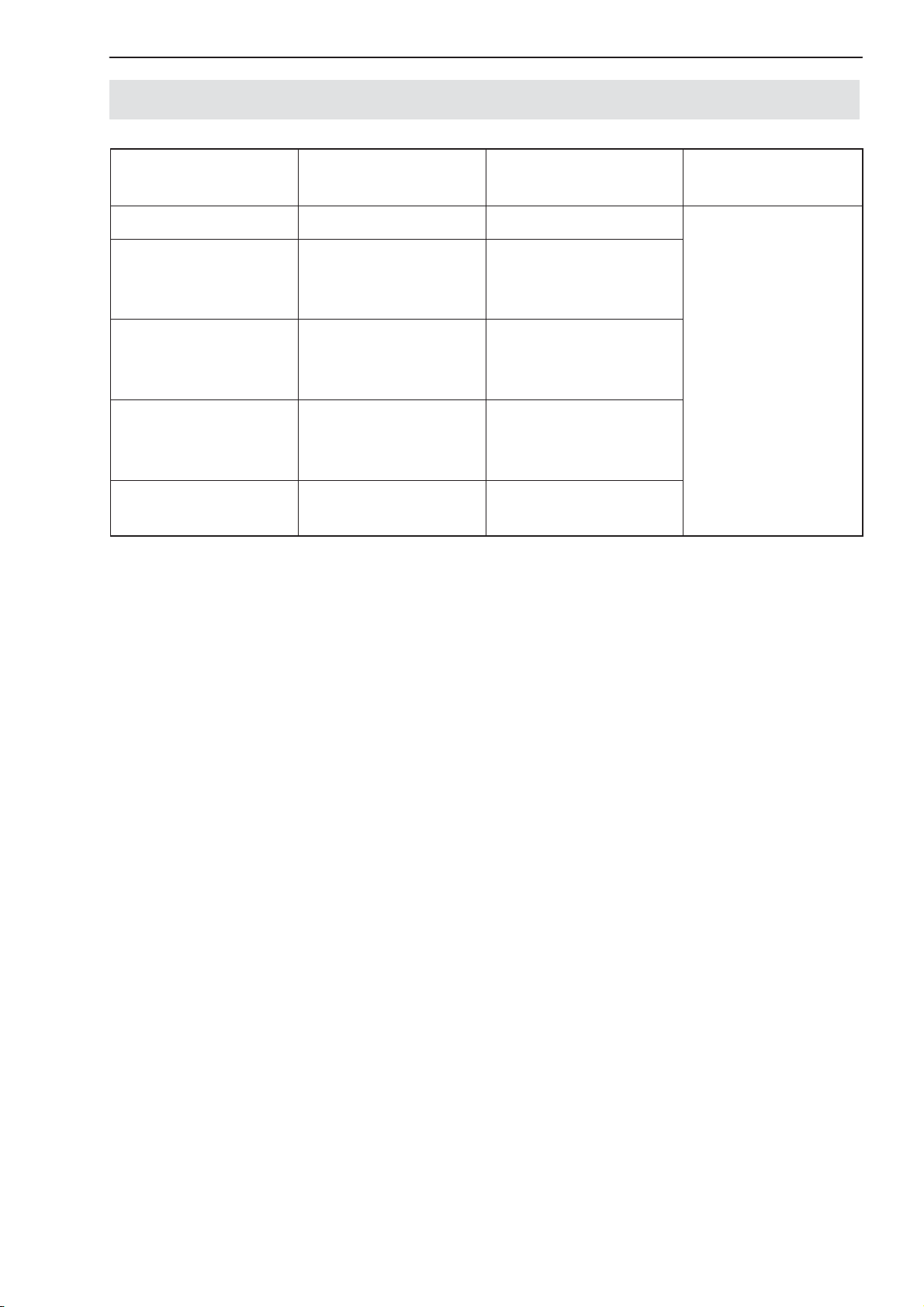
2.1 Configuration
7
Basic device,
type
AED9101D RS232, RS485 Trigger input
AED9201B RS232, RS485 Digital I/O
AED9301B PROFIBUS Digital I/O
AED9401A CANopen or
AED9501A CANopen or
Digital inputs and outputs allow:
• processes to be controlled via four limit values
Interfaces Inputs / outputs Amplifier to
(electrically
isolated)
(electrically
isolated)
Digital I/O
DeviceNet
DeviceNet
(electrically
isolated)
Trigger input
install
AD103C
• triggered measured values to be determined (MAV) and
• a filling or dosing process to be controlled.
• A diagnostic function has been built into the AD103C to analyze dynamic
measurement. This function includes a memory for 512 (binary) measured
values and associated status information. Different recording modes are
available so that the processes can be analyzed without interrupting measurement.
A1780−4.3 en/de/fr/es/it HBM

8
AED System Digital Transducer Electronics
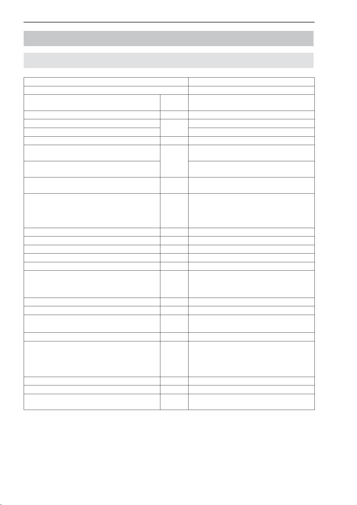
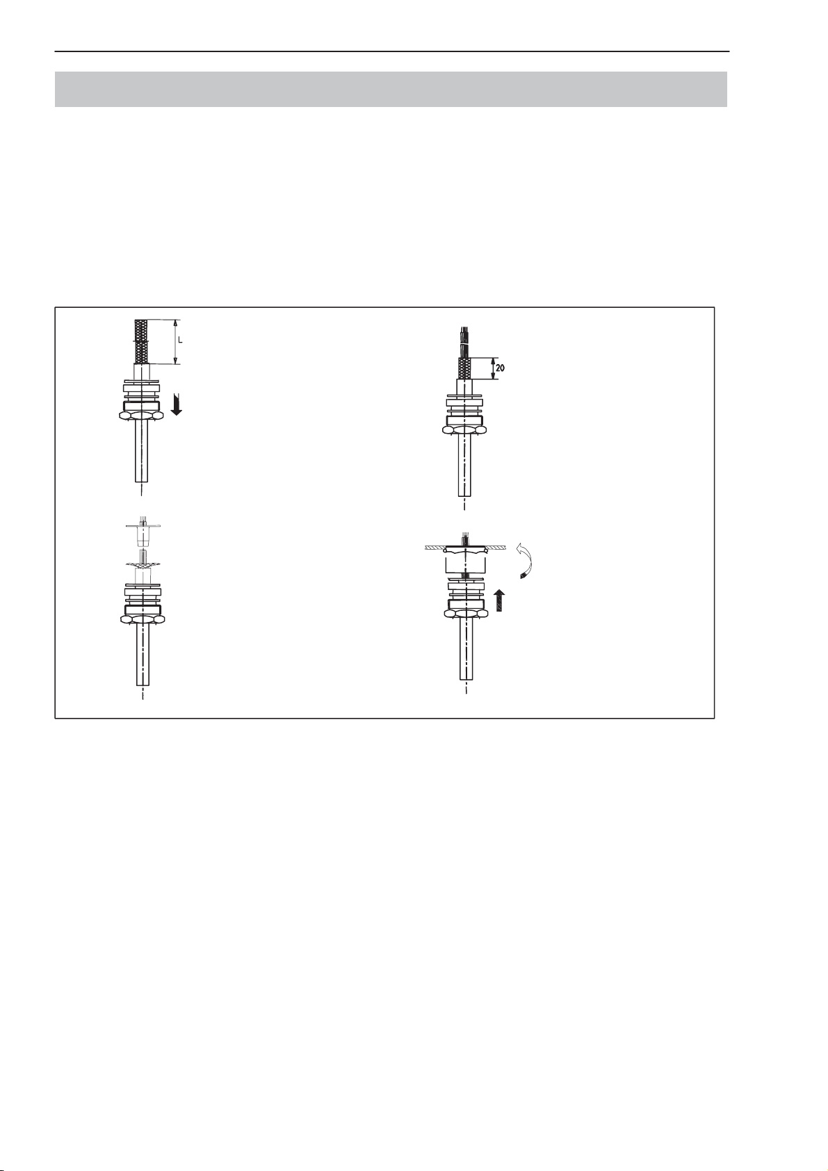
3 Cable connection via a PG gland
Only a connecting cable with a screen grounded on both sides (and metal connectors) should be used as the connecting cable between the AED9x01A and
its partner device. Bring the screen extensively into contact on both sides at
the PG gland and at the metal shell of the connector. If the partner device does
not have a metal connector, connect the cable shielding extensively to ground.
If there are vast differences between the ground potential of the AED and its
partner device, a potential equalization line must be provided in addition.
1
2
Remove the outer sheath
of the cable to the required
length of wire L.
Push the screwed cable
gland with the gasket and
thrust collars over the end
of the cable.
Fan out the cable shielding
radially.
Push the ground sleeve
between the wires and the
cable shielding until it
comes to a stop, press the
shielding to the sleeve
flange, cut off any excess.
3
4
Strip the insulation from the
wire ends and tin them.
Shorten the cable shielding
and tin the stranded wires.
Push the cable through the
intermediate supports on
the casing until it comes to
a stop, bring the screwed
cable gland forward and
screw down tightly.
Fig. 1: Cable connection via a PG gland
A1780−4.3 en/de/fr/es/itHBM
AED System Digital Transducer Electronics
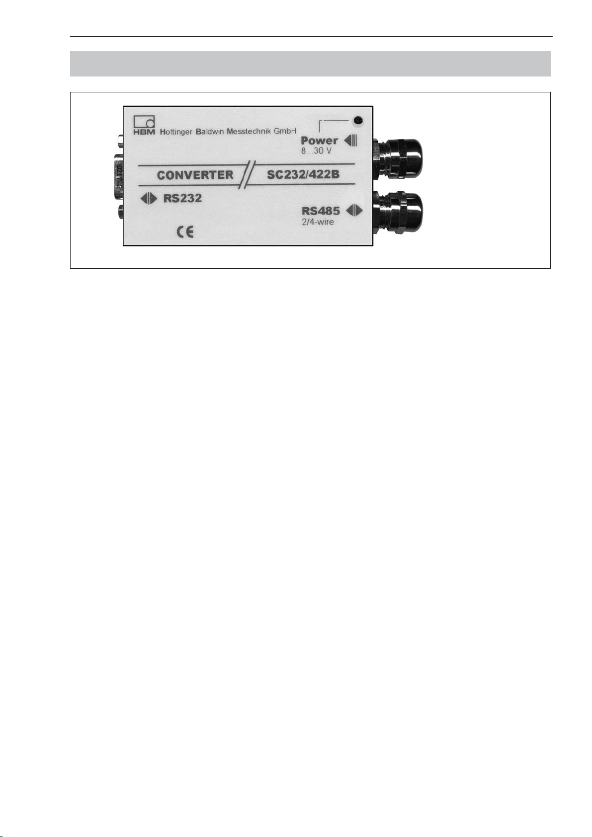
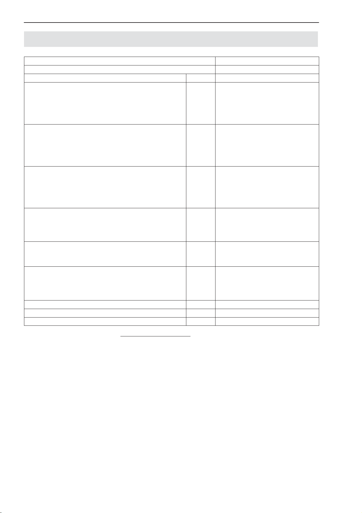
4 Serial communication via the RS485 interface
Fig. 2: HBM SC232/422B interface converter
The HBM program includes an interface converter (part no. 1-SC232/422B),
which allows an RS-485 bus to be connected to an RS-232 interface.
9
A1780−4.3 en/de/fr/es/it HBM
10
AED System Digital Transducer Electronics
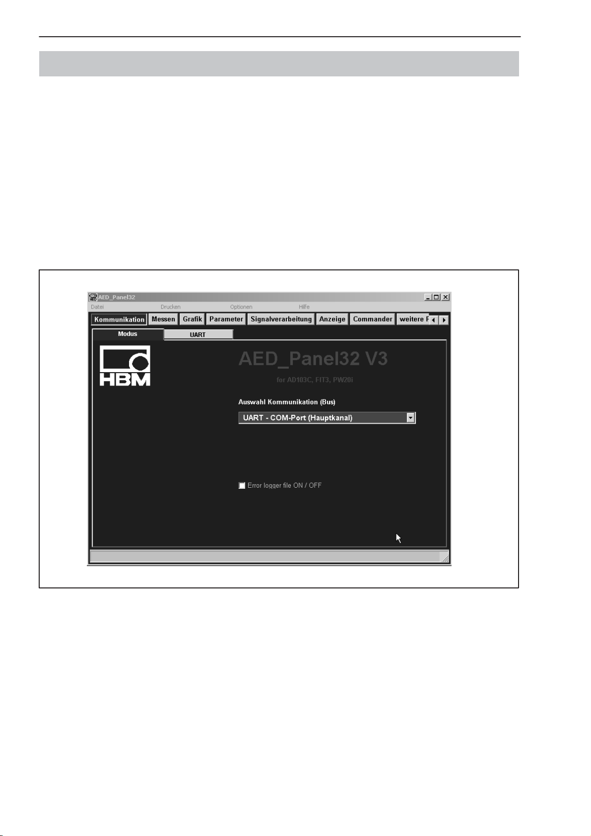
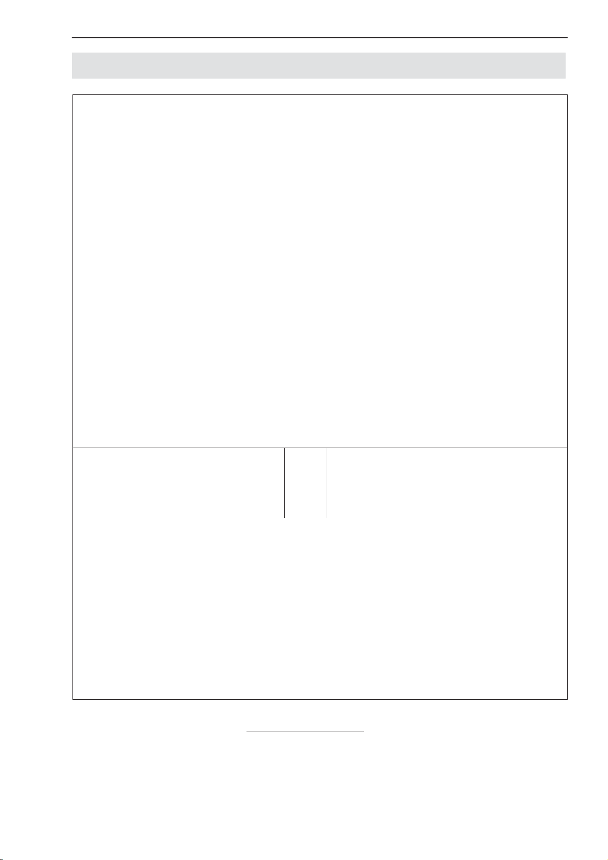
5 HBM software program
HBM provides a panel program for setting up the AED:
AED_Panel32 (from Version 3.0.0)
for PROFIBUS connection to a PC:
Adapter CP5511, CP5611 (Siemens)
for CAN / DeviceNet connection to a PC:
PCAN = USB adapter (PEAK-System Technik)
Please take note of the readme.txt files.
The program can be found on the CD-ROM ”1-FIT-AED-DOC” or under
www.hbm.com − Products & Service − Software
Fig. 3: AED_Panel32 program screen display
A1780−4.3 en/de/fr/es/itHBM
AED System Digital Transducer Electronics
11
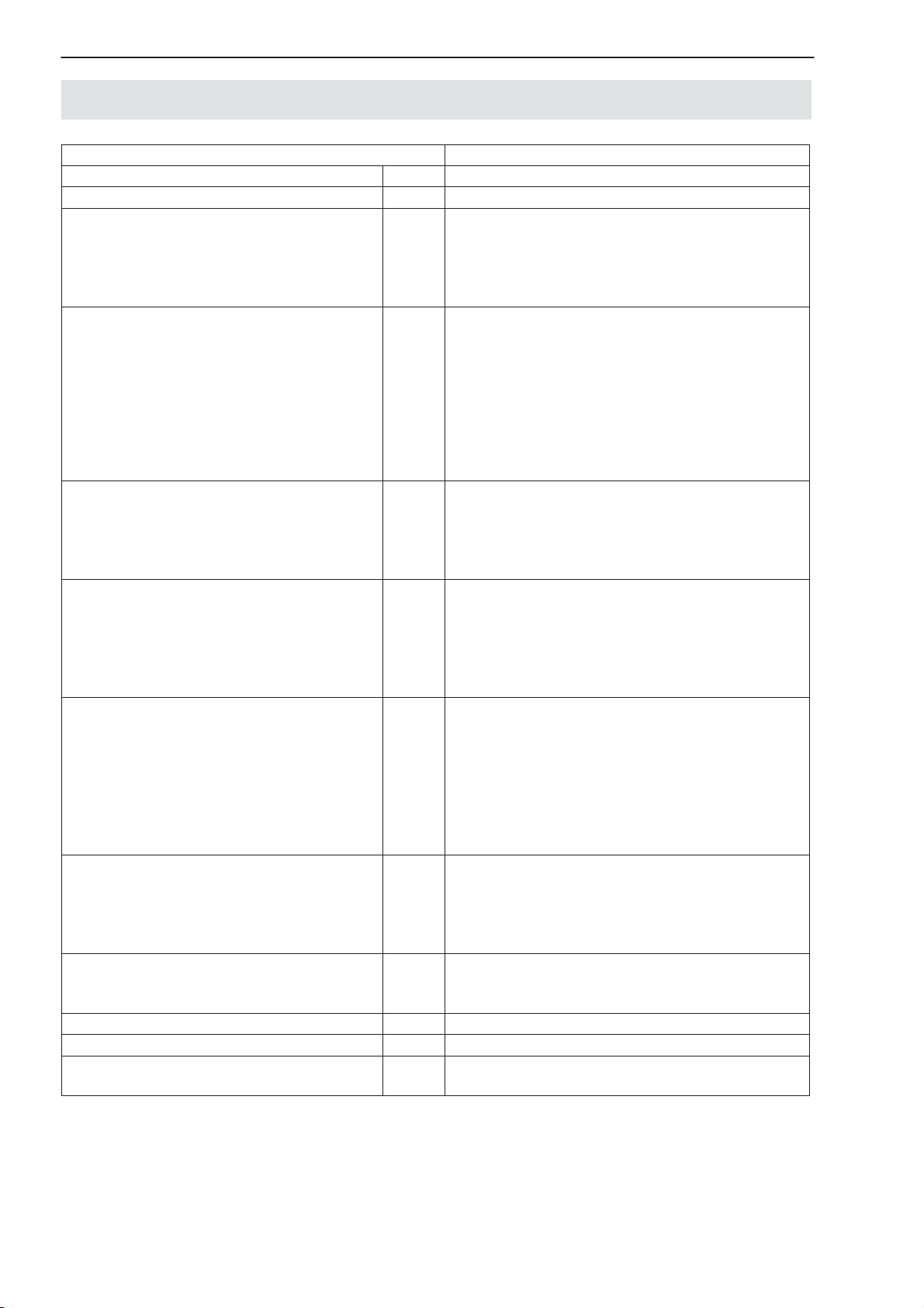
6 Mechanical construction of the basic devices
Amplifier boards are designed as a plug-in board and plug into the carrier
board in the basic device via a 25–pin sub-D connector. The basic device contains the terminals for the transducer, power pack and interface connections,
the slide switch for interface selection and the voltage stabilizer. The connection cables exit the casing via PG glands on the side.
A connection diagram is attached inside the lid of the each basic device. When
making the connections, ensure that the wires of the cable do not protrude beyond the connection terminals (risk that loops may form). Make sure that the
cable shielding is properly connected to the PG gland (see Figure 1).
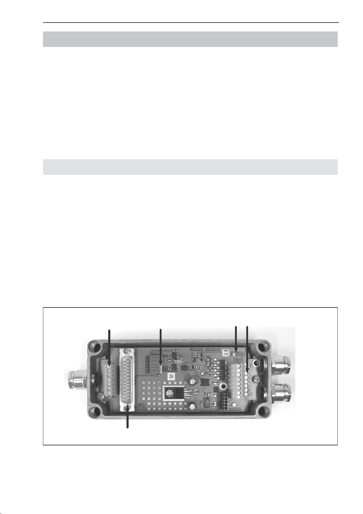
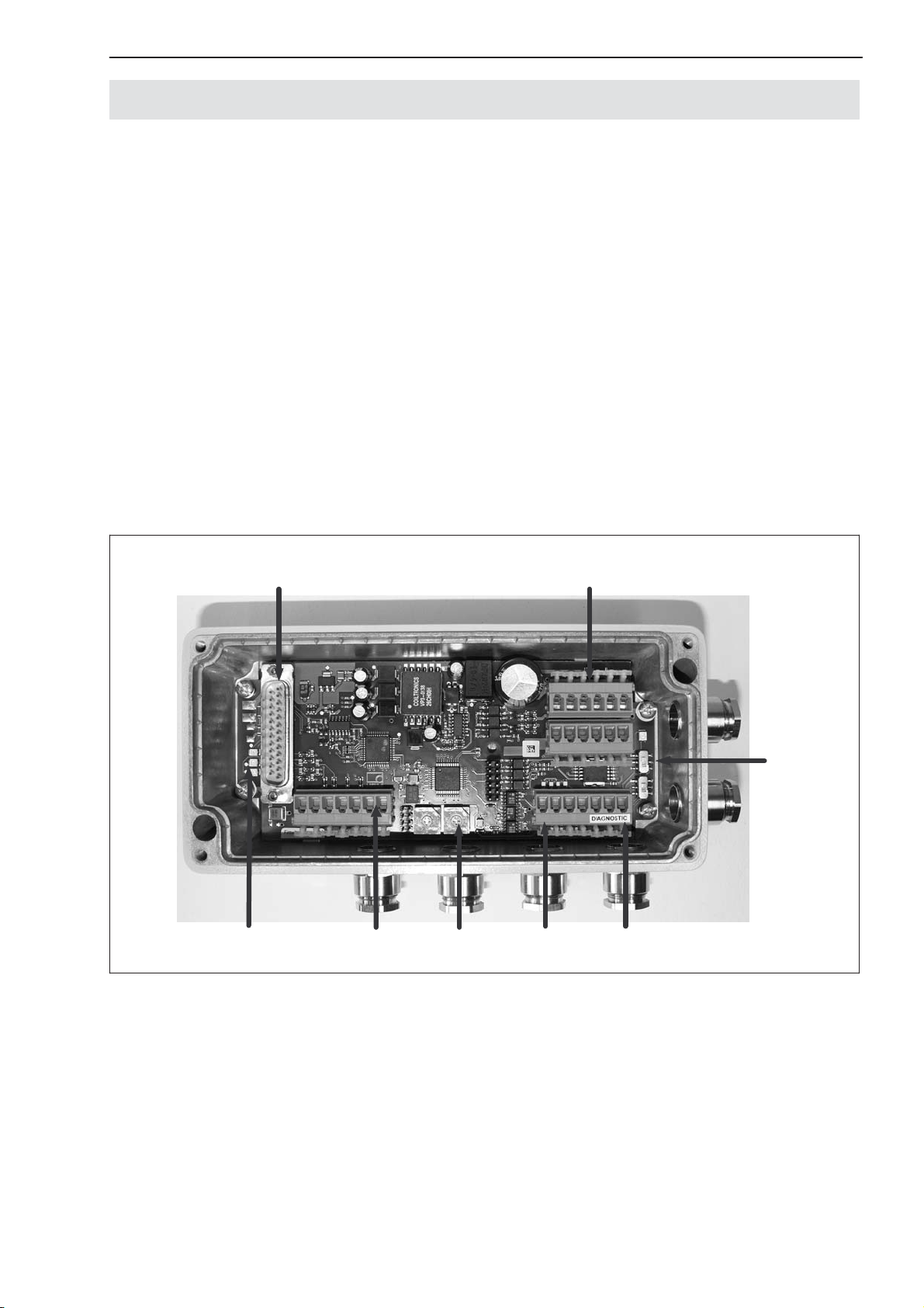
6.1 AED9101D basic device
The AED9101D basic device extends the functionality of the AD amplifier
board and provides:
• mechanical protection (IP65)
• a slot for the AD103C amplifier board
• a voltage supply for the amplifier board and transducer excitation (5 VDC)
• total transducer bridge resistance 40 Ω ... 4000 Ω
• a choice of RS-422, RS-485 and RS-232 serial interfaces
• a digital input
• EMC protection
Load cell
connections
Interface
settings
RS-485 bus
termination
Interface, voltage supply,
trigger input, Diagnostic
Connection for
amplifier
Fig. 4: Mechanical construction of the AED9101D (for pin assignment and setup, see sticker in lid)
A1780−4.3 en/de/fr/es/it HBM
12
AED System Digital Transducer Electronics
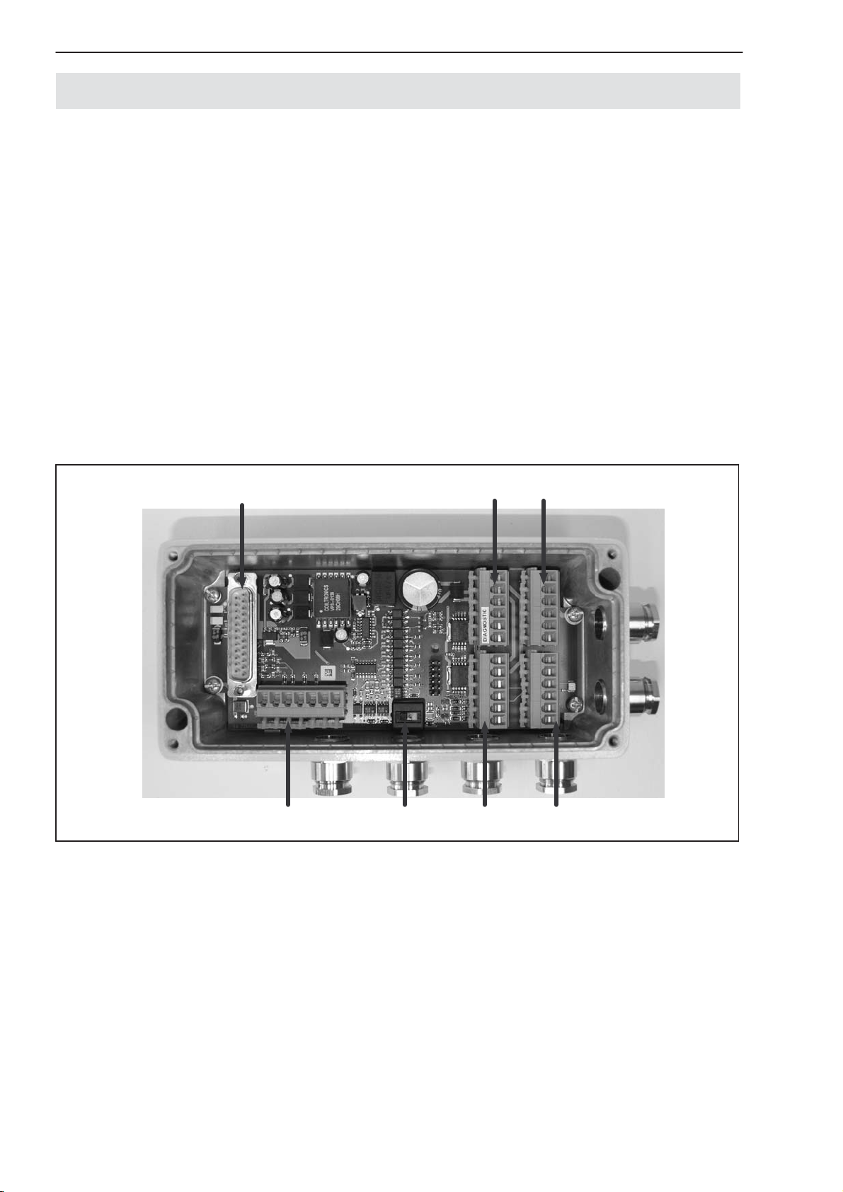
6.2 AED9201B basic device
The AED9201B basic device extends the functionality of the AD amplifier
board and provides:
• mechanical protection (IP65)
• a slot for the AD103C amplifier board
• a voltage supply for the amplifier board and transducer excitation (5 VDC)
• total transducer bridge resistance 80 Ω...4000 Ω
• a choice of RS-485 (4-wire) and RS-232 (electrically isolated from the ampli-
fier) serial interfaces
• two digital inputs and six digital outputs (electrically isolated from the amplifier)
• EMC protection
Connection for amplifier
Transducer
connection
Fig. 5: Mechanical construction of the AED9201B (for pin assignment and setup, see sticker in lid)
Interface
changeover switch
Connections for digital I/O
Connections for
power supply and interface
A1780−4.3 en/de/fr/es/itHBM
AED System Digital Transducer Electronics
13
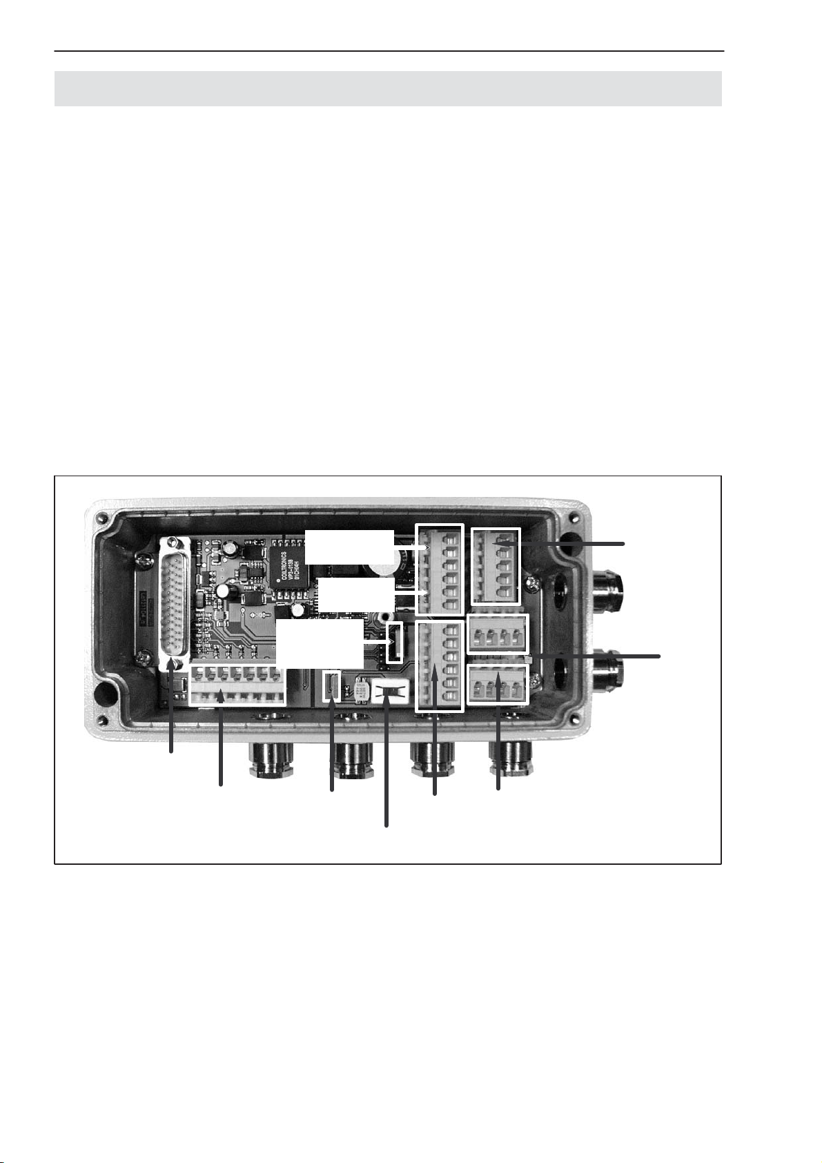
6.3 AED9301B basic device
The AED9301B basic device extends the functionality of the AD amplifier
board and provides:
• mechanical protection (IP65)
• a slot for the AD103C amplifier board
• a voltage supply for the amplifier board and transducer excitation (5 VDC)
(electrically isolated)
• total transducer bridge resistance 80 Ω ... 4000 Ω
• a PROFIBUS interface (electrically isolated from the amplifier and from the
digital inputs / outputs)
• two digital inputs and four digital outputs (electrically isolated from the amplifier and from PROFIBUS)
• EMC protection
Connector for
amplifier
PROFIBUS
light-emitting
diodes
Transducer
connection
Address
settings
Voltage supply
and digital I/O
PROFIBUS
connection
Diagnostics bus
Bus termination and
diagnostics switch
Fig. 6: Mechanical construction of the AED9301B (for pin assignment and setup, see sticker in lid)
A1780−4.3 en/de/fr/es/it HBM
14
AED System Digital Transducer Electronics
6.4 AED9401A basic device
The AED9401A basic device extends the functionality of the AD amplifier
board and provides:
• mechanical protection (IP65)
• a slot for the AD103C amplifier board
• a voltage supply for the amplifier board and transducer excitation (5 VDC)
(electrically isolated)
• total transducer bridge resistance 80 Ω ... 4000 Ω
• an interface for CANopen and DeviceNet (electrically isolated from the am-
plifier)
• two digital inputs and four digital outputs (electrically isolated from the amplifier)
• EMC protection
Connector
for amplifier
Load cell
connection
Power supply
Digital
outputs
Bus select.
CAN Bus
DeviceNet
Bus
termination
Diagnostic
Bus
Bus disconnection
Digital
inputs
LED
Power supply
Bus CAN/
DeviceNet
Fig. 7: Mechanical construction of the AED9401A (for pin assignment and setup, see sticker in lid)
A1780−4.3 en/de/fr/es/itHBM
AED System Digital Transducer Electronics
15
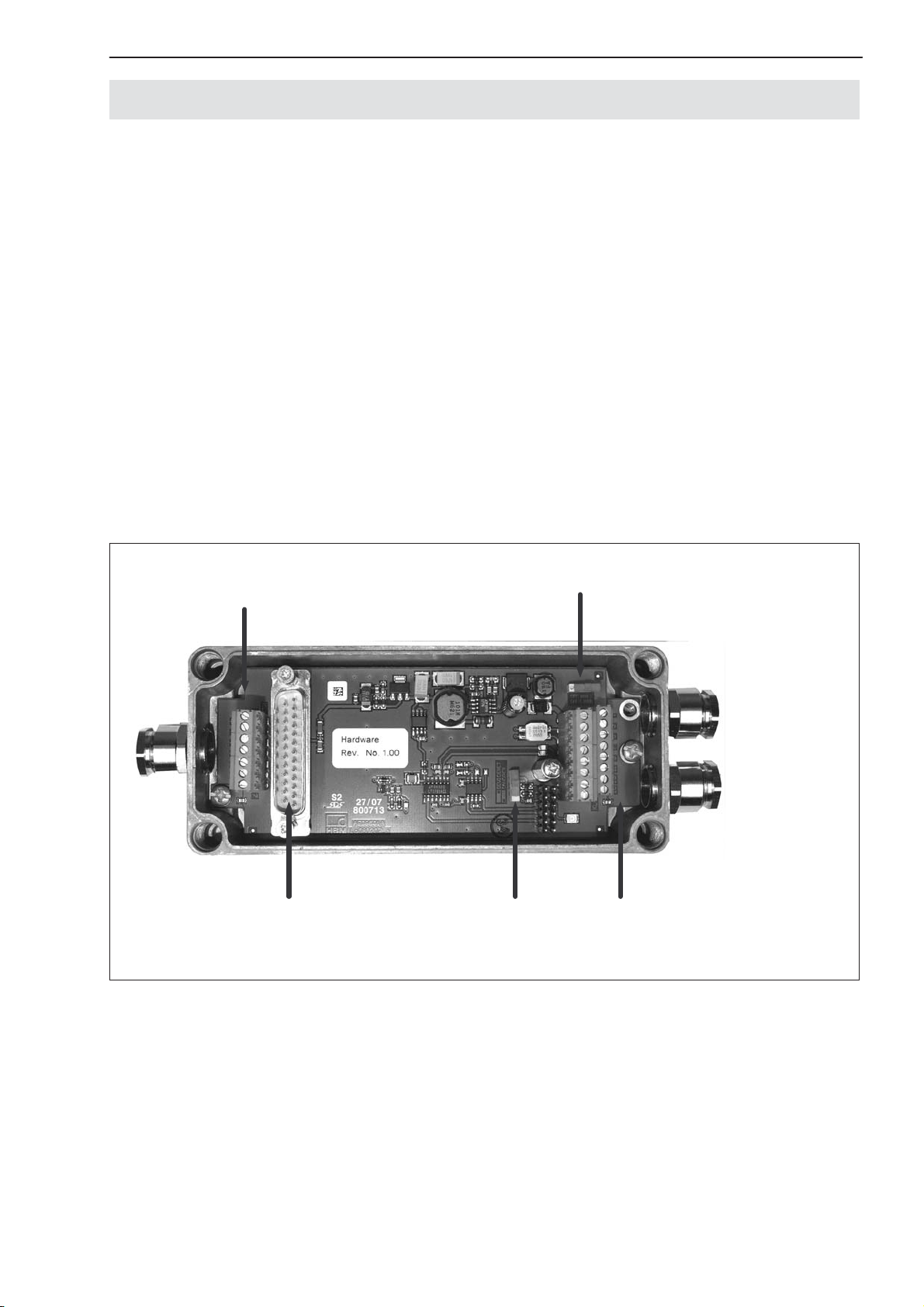
6.5 AED9501A basic device
The AED9501A basic device extends the functionality of the AD amplifier
board and provides:
• mechanical protection (IP65)
• a slot for the AD103C amplifier board
• a voltage supply for the amplifier board and transducer excitation (5 VDC)
(electrically isolated)
• total transducer bridge resistance 80 Ω ... 4000 Ω
• an interface for CANopen and DeviceNet (electrically isolated from the am-
plifier)
• Diagnostic bus
• Digital input IN1
• EMC protection
Load cell
connection
Amplifier connection
AD103C
Interface
settings
Bus termination
Interface, power supply
and trigger input terminals
Fig. 8: Mechanical construction of the AED9501A (for pin assignment and setup, see sticker in lid)
A1780−4.3 en/de/fr/es/it HBM
16
AED System Digital Transducer Electronics
7 Specifications
7.1 AD101B amplifier board specifications
Type AD101B
Accuracy class (with int. calibration) 0.015
Number of trade values, acc. to
EN 45501 (R76)
Input sensitivity μV/e 1
Measuring range
Input signal range ±3.0
Measuring signal resolution, max. bit 20 (at 1 Hz)
Measuring rate (depending on output
format and baud rate)
Cut-off frequency of the digital filter
(−3 dB), adjustable
Bridge excitation voltage U
(Excitation from supply voltage)
Measuring signal input, Strain gage
transducers (Full bridge)
Transducer connection
Input resistance (differential)
Transducer cable length m ≤100, in case of calibration incl. cable
Interface cable length RS-232 m ≤15 (25 pol. female connector)
Calibration signal mV/V 2±0.01 %
Temperature stability of the calibr. signal ppm/°C ≤2.5
Linearity error (related to full scale) % ±0.01
Temperature effect on
zero point (related to full scale)
measuring sensitivity (rel. to actual value)
Interface RS-232
Baud rate, adjustable bit/s 1200 ... 38400
Supply voltage V
Current consumption (without load cell) mA ≤ 80
Temperature range:
Nominal temperature
Service temperature
Storage temperature
Dimensions mm 93 x 53 x 17
Weight, approx. g 40
Degree of protection according to
EN 60529 (IEC 529)
1)
Depending on the external supply voltage
B
d 6000
mV/V
600 ... 4.7
Hz
40 ... 0.25
V
DC
Ω
MΩ
%/10K
DC
°C [°F]
5 ... 10 (= supply voltage!)
≥40...4000
6-wire circuit
typ. ± 0.005; max. 0.01
typ. ± 0.005; max. 0.01
residual ripple ≤10 mV (p.p.)
−10...+40 [+14...+104]
−20...+60 [−4...+140]
−25...+85 [−13...185]
±2.0
1)
>15
5 ... 10
IP00
Not intended for use with AED9401A, AED9501A and CANopen/DeviceNet communication.
A1780−4.3 en/de/fr/es/itHBM

AED System Digital Transducer Electronics
7.2 AD103C amplifier board specifications
Type AD103C
Accuracy class 0.01
Number of trade values, accord. to EN 45
501 (R76)
Input sensitivity μV/e 0.5
Measuring range
Input signal range, max. ±3.0
Measuring signal resolution, max. bit 24
Measuring rate (depending on output
format and baud rate)
Cutt-off frequency of the digital filter
(−3 dB), adjust.
Bridge excit. voltage U
(Excit. from supply
B
voltage)
Measuring signal input, SG transducer
(Full bridge)
Transducer connection
Input resistance (differentiell)
Transducer cable length m ≤100, calibration incl. cable
Interface cable length RS-232 m ≤15 (25-pol. Sub-D-female connector)
Calibration signal mV/V 2±0.01 %
Temperature stability of the calibration
signal
Linearity deviation (related to full scale
value)
Temperature effect on
zero point (related to full scale value)
measuring sensitivity (related to actual
value)
Interface RS-232
Baud rate, adjustable bit/s 1200 ... 115 200
Diagnostics interface (RS-232)
Protocol
Baud rate
Node address
Length of interface cable, max.
Supply voltage V
Current consumption (wthout load cell) mA ≤ 90
Nominal temperature range
Operating temperature range
Storage temperature range
Dimensions (LxWxH) mm 93 x 53 x 17
Weight, approx. g 40
Degree of protection to EN60529
(IEC 529)
1)
Depending on the external customer side supply voltage or from the basic unit
e 10 000
mV/V
±2.0
1200 ... 4.7
Hz
200 ... 0.25
V
DC
Ω
5 ±5 % (= supply voltage)
≥40...4000
6-wire circuit
MΩ
>15
ppm/°C ≤2.5
% ±0.002
%/10 K
typ. ± 0.0025; max. 0.005
typ. ± 0.0025; max. 0.005
ASCII/Binary
kbit/s
38.4
0...89
m
DC
5 ±5 %; Residual ripple ≤10 mV (p.p.)
≤15
−10 ... +40 [14...104]
°C [°F]
−20 ... +60 [−4...140]
−25 ... +85 [−13...185]
IP00
1)
17
A1780−4.3 en/de/fr/es/it HBM
18
AED System Digital Transducer Electronics
7.3 AED9101D basic device specifications
Type AED9101D
Measuring amplifier AD103C
Measurement signal input mV/V ±3, nominal ±2
Transducer connection
SG transducer (full bridge)
Transducer connection type
Length of transducer cable
Bridge excitation voltage
Interfaces
Hardware (selected by slide-switch)
Length of communications cable RS232
RS422, RS485
Max. number of bus nodes (RS485)
Diagnose bus (RS-485 2-wire)
Protocol
Baud rate, max.
Node address
Length of communications cable, max.
Trigger input
Input voltage range, LOW
Input voltage range, HIGH
Input voltage range at High level = 30 V
Power supply
Supply voltage
Current consumption (without load cell)
Temperature range
Nominal (rated) temperature
Operation temperature
Storage temperature
Dimensions mm 190 x 65 x 40
Weight, approx. g 440 (without AD10x)
Degree of protection per EN 60529 (IEC 529) IP65
1)
Current consumption: ≤100 mA +
Excitation voltage U
Bridge resistance R
= 5 V
B
B
Ω
m
V
DC
m
m
kbit/s
m
V
V
mA
V
DC
mA
° C
40 … 4000
6-wire circuit
≤ 100
5
RS232, RS422, RS485
≤ 15
≤ 1000
32
ASCII/binary
38,4
0 … 89
1000
0 … 1
2 … 30
< 3
10 … 30
≤ 100
1)
−10 … +40
−20 … +60
−25 … +85
A1780−4.3 en/de/fr/es/itHBM
AED System Digital Transducer Electronics
7.4 AED9201B basic device specifications
Type AED9201B
Measuring amplifier AD103C
Measuring signal input mV/V ±3, nominal ±2
Transducer connection:
Strain gage transducer (full bridge)
Ω
Transducer connection
Transducer cable length
Bridge excitation voltage
m
V
DC
Interfaces:
Hardware (select. via slide switch)
Interface cable length RS-232
RS-485
m
m
RS-232, RS-485 (4 wire)
Max. number of bus members
Control inputs (electrically isolated):
Number
Input voltage range, LOW
Input voltage range, HIGH
Input current, typ., HIGH-level = 24 V
Insulation voltage, typ.
Control outputs 1) (electric. isolated):
V
V
mA
V
DC
Supply from supply voltage
Number
Output current at LOW level (IOUT)
Output voltage HIGH level (UOUT)
Output current, max. (IOUT
max
)
Insulation voltage, typ.
mA
V
mA
V
DC
Diagnostics bus:
Protocol
Baud rate, max.
kbit/s
Node address
Length of Interface cable, max.
m
Supply:
Supply voltage (DC), nominal
Supply voltage (DC), minimal
Current consumption (without load
V
V
mA
cell and Output current)
Temperature range:
Nominal temperature
Operating temperature
°C[°F]
Storage temperature
Dimensions mm 195 x 100 x 70
Weight, approx. g 925 (without AD10x)
Degree of protection
according to EN 60529 (IEC 529)
1)
Depending on the external supply voltage
2)
Current consumption: ≤175 mA +
Supply voltage UB = 5 V
Bridge resistance R
B
+ ∑ I
≥80...4000
6-wire circuit
≤100
5
≤15
≤1000
90
2
0...5
10...30
typ. 12
500
4
<2
>15 at I
max
< 500, per output
500
ASCII/Binary
38.4
0 ... 89
1000
18...30
15
2)
≤175
−10...+40 [+14...+104]
−20...+60 [−4...+140]
−25...+85 [−13...+185]
IP65
1...6
out
19
A1780−4.3 en/de/fr/es/it HBM
20
AED System Digital Transducer Electronics
7.5 AED9301B basic device specifications
Type AED9301B
Measuring amplifier AD103C
Measuring signal input mV/V ±3, nominal ±2
Transducer connection:
Strain gage transducer (full bridge)
Transducer connection
Transducer cable length
Bridge excitation voltage
PROFIBUS DP:
Protocol
Bit rate, max.
Subcriber adress, set by rotary switch
Interface cable length PROFIBUS
Diagnostics bus:
Protocol
Baud rate
Node address
Length of Interface cable, max.
Control inputs (electrically isolated):
Number
Input voltage range, LOW
Input voltage range, HIGH
Input current, typ., HIGH−level = 24V
Insulation voltage, typ.
Control outputs 1) (elect. isolated):
Number
Max. output current I
Short circ.cur., typ., U
per output
max
=24V; RL <0.1Ω
b
Short circuit duration
Input current at LOW level
Output voltage HIGH level
Insulation voltage, typ.
Supply:
Supply voltage
Current consumption (withload cell,
RB = 80 Ω, and addit. output current
of control output I
out
1...4)
Temperature range: Nom. temperat.
Operating temperature
Storage temperature
Dimensions mm 195 x 100 x 70
Weight, approx. g 925 (without AD10x)
Degree of protection according to EN
60529 (IEC 529)
Ω
m
V
DC
Mbit/s
m
kbit/s
m
V
V
mA
V
DC
A
A
mA
V
V
DC
V
DC
mA
°C
[°F]
≥80...4000
6-wire circuit
≤100
5
PROFIBUS-DP Slave, acc. to DIN 19245-3
12
3...99
1200 (at 9.6 / 19.2 / 93.75 kbit/s)
1000 (at 187.5 kbit/s)
400 (at 500 kbit/s)
200 (at 1.5 Mbit/s)
100 (at 12 Mbit/s)
ASCII/Binary
38.4
0 ... 89
1000
2
0...5
10...30
12
500
Supply from supply voltage
4
0.5
0.8
Unlimited
<2
>15 at I
max
500
18...30
2)
≤250
−10...+40 [+14...+104]
−20...+60 [−4...+140]
−25...+85 [−13...+185]
IP65
1) Depending on the external supply voltage
2)
Current consumption at 18 V−Supply: 250 mA + IOUT 1...4
at 24 V−Supply: 200 mA + IOUT 1...4
at 30 V−Supply: 170 mA + IOUT 1...4
IOUT 1...4 = Current of the control outputs
A1780−4.3 en/de/fr/es/itHBM
AED System Digital Transducer Electronics
7.6 AED9401A basic device specifications
Type AED9401A
Measuring amplifier AD103C
Measuring signal input mV/V ±3, nominal ±2
Transducer connection:
Strain gage transducer (full bridge)
Transducer connection
Transducer cable length
Bridge excitation voltage
CAN-Bus:
Protocol
Bit rate, max.
Node address
Length of Interface cable
DeviceNet-Bus:
Protocol
Bit rate, max.
Node address
Length of Interface cable
Diagnostics bus:
Protocol
Baud rate
Node address
Length of Interface cable, max.
Control inputs (electrically isolated):
Number
Input voltage range, LOW
Input voltage range, HIGH
Input current, typ., HIGH−level = 24V
Control outputs 1) (electr. isolated):
Number
Max. output current I
Short circ. cur., typ., U
per output
max
=24V; RL<0.1Ω
b
Short circuit duration
Input current at LOW level
Output voltage HIGH level
Insulation voltage, typ.
Supply:
Supply voltage
Current consumption (with load cell,
RB = 80 Ω and addition. output
current of the control output I
out
1...4)
Temperature range: Nom. temperat.
Operating temperature
Storage temperature
Dimensions mm 195 x 100 x 70
Weight, approx. g 925 (without AD10x)
Degree of protection according to EN
60529 (IEC 529)
1) Depending on the external supply voltage
2)
Current consumption at 18 V−Supply: 250 mA + IOUT 1...4
at 24 V−Supply: 200 mA + IOUT 1...4
at 30 V−Supply: 170 mA + IOUT 1...4
IOUT 1...4 = Current of the control outputs
Ω
m
V
DC
kbit/s
m
kbit/s
m
kbit/s
m
V
V
mA
A
A
mA
V
V
DC
V
DC
mA
°C[°F]
≥80...4000
6-wire circuit
≤100
5
CANopen
10 ... 1000
1 ... 127
5000 ... 25
DeviceNet
125 ... 500
1 ... 63
1000 ... 100
ASCII/Binary
38.4
0 ... 89
1000
2
0...5
10...30
12
Supply from supply voltage
4
0.5
0.8
Unlimited
<2
>15 at I
max
500
18...30
2)
≤250
−10...+40 [+14...+104]
−20...+60 [−4...+140]
−25...+85 [−13...185]
IP65
21
A1780−4.3 en/de/fr/es/it HBM

22
AED System Digital Transducer Electronics
7.7 AED9501A basic device specifications
Type AED9501A
Amplifier board AD103C
Measurment signal input
SG transducer (1...4 full bridge, each 350Ω), R
Transducer connection
Length of transducer cable
Bridge excitation voltage
CANopen
Protocol
Bit rate, max.
Node address
Length of interface cable
DeviceNet bus
Protocol
Bit rate, max.
Node address
Length of interface cable
Diagnostics bus
Protocol
Baud rate
Node address
Length of interface cable, max.
Trigger input
Input voltage range, LOW
Input voltage range, HIGH
Input current with High level = 30 V
Power supply
Supply voltage (DC)
Current consumption (without load cell)
Temperature range
Nominal temperature range
Operating temperature range
Storage temperature range
Miscellaneous
Dimensions (L x W x H)
Weight, approx.
Degree of protection to EN 60529 (IEC529)
B
mV/V
Ω
m
V
DC
kbit/s
m
kbit/s
m
kbit/s
m
V
V
mA
V
mA
°C [°F]
°C [°F]
°C [°F]
mm
g
3, nominal 2
80...4000
6 wire circuit
≤ 100
5
CANopen
10...1000
1...127
5000...25
DeviceNet
125...500
1...63
1000...100
ASCII/Binary
38.4
0...89
1000
0...1
2...30
< 3
10...30
1)
≤ 120
−10...+40 [+14...+104]
−20...+60 [−4...+140]
−25...+85 [−13...+185]
190 x 65 x 40
440 (without AD10x)
IP65
1)
Current consumption: ≤120 mA +
Excitation voltage UB = 5 V
Bridge resistance R
B
A1780−4.3 en/de/fr/es/itHBM

Digitale Aufnehmerelektroniken AED-System
1 Sicherheitshinweise 24..........................................
2 Beschreibung und bestimmungsgemäße Verwendung 26..........
2.1 Aufbau 27.................................................
3 Kabelanschluss über PG-Verschraubung 28......................
4 Serielle Kommunikation über RS-485-Schnittstelle 29.............
5 HBM-Software-Programm 30....................................
6 Mechanischer Aufbau der Grundgeräte 31........................
6.1 Grundgerät AED9101D 31...................................
6.2 Grundgerät AED9201B 32...................................
6.3 Grundgerät AED9301B 33...................................
6.4 Grundgerät AED9401A 34...................................
6.5 Grundgerät AED9501A 35...................................
23
7 Technische Daten 36............................................
7.1 Technische Daten Messverstärkerplatine AD101B 36............
7.2 Technische Daten Messverstärkerplatine AD103C 37............
7.3 Technische Daten Grundgerät AED9101D 38..................
7.4 Technische Daten Grundgerät AED9201B 39...................
7.5 Technische Daten Grundgerät AED9301B 40...................
7.6 Technische Daten Grundgerät AED9401A 41...................
7.7 Technische Daten Grundgerät AED9501A 42...................
A1780−4.3 en/de/fr/es/it HBM

24
Digitale Aufnehmerelektroniken AED-System
1 Sicherheitshinweise
Befolgen und beachten Sie außer den nachfolgenden Hinweisen, die ausführlichen sicherheitsrelevanten Angaben und die Spezifikationen in den
individuellen Unterlagen der Geräte.
Wichtige Hinweise
Das Gerät darf ohne unsere ausdrückliche Zustimmung weder konstruktiv
noch sicherheitstechnisch verändert werden. Jede Änderung schließt eine Haftung unsererseits für daraus resultierende Schäden aus.
Insbesondere sind jegliche Reparaturen untersagt. Reparaturen dürfen nur von
HBM durchgeführt werden.
Die komplette Werkseinstellung wird im Werk netzausfallsicher und nicht
lösch− oder überschreibbar gespeichert und kann mit dem Befehl TDD0 jederzeit wieder eingestellt werden.
Die im Werk eingestellte Fertigungsnummer sollte nicht verändert werden.
Der Aufnehmeranschluss muss immer beschaltet sein. Schließen Sie zum
Betrieb unbedingt eine Brückennachbildung an.
Allgemeine Gefahr bei Nichtbeachten der Sicherheitshinweise
Die HBM-Komponenten entsprechen dem Stand der Technik und sind betriebssicher. Von den Komponenten können Restgefahr ausgehen, wenn sie
von ungeschultem Personal unsachgemäß eingesetzt und bedient werden.
Jede Person, die mit Aufstellung, Inbetriebnahme, Wartung oder Reparatur der
Komponenten beauftragt ist, muss die Bedienungsanleitung und insbesondere
die sicherheitstechnischen Hinweise gelesen und verstanden haben.
Im Normalfall gehen von diesem Produkt keine Gefahren aus, sofern die Hinweise und Anleitungen für Projektierung, Montage, bestimmungsgemäßen Betrieb und Instandhaltung beachtet werden.
Die für die jeweilige Anwendung geltenden Sicherheits- und Unfallverhütungsvorschriften sind unbedingt zu beachten.
Montage und Inbetriebnahme darf ausschließlich durch qualifiziertes Personal
vorgenommen werden.
A1780−4.3 en/de/fr/es/itHBM

Digitale Aufnehmerelektroniken AED-System
25
Vermeiden Sie die Einwirkung von Schmutz und Feuchtigkeit.
Treffen Sie bei der Montage und beim Anschluss der Leitungen Maßnahmen
gegen elektrostatische Entladungen, die die Elektronik beschädigen können.
Zur Stromversorgung ist eine Kleinspannung mit sicherer Trennung vom Netz
erforderlich.
Beim Anschluss von Zusatzeinrichtungen sind die allgemeinen Sicherheitsbe-
stimmungen einzuhalten.
Für alle Verbindungen sind geschirmte Leitungen zu verwenden. Der Schirm
ist beidseitig flächig mit Masse zu verbinden. Leitungen zur Anbindung der
Versorgung sowie der Digital-I/O sind nur dann geschirmt auszuführen, falls
eine Kabellänge von 30 m überschritten wird oder falls die Leitungen
außerhalb geschlossener Gebäude verlegt werden.
A1780−4.3 en/de/fr/es/it HBM

26
Digitale Aufnehmerelektroniken AED-System
2 Beschreibung und bestimmungsgemäße Verwendung
Die AED-Aufnehmerelektroniken sind ausschließlich für Messaufgaben mit
DMS-Vollbrücken-Aufnehmer und direkt damit verbundene Steuerungs- und
Regelaufgaben zu verwenden. Jeder darüber hinausgehende Gebrauch gilt als
nicht bestimmungsgemäß.
Zur Gewährleistung eines sicheren Betriebes dürfen die Aufnehmerelektroniken nur nach den Angaben in der Bedienungsanleitung betrieben
werden. Bei der Verwendung sind zusätzlich die für den jeweiligen
Anwendungsfall erforderliche Rechts- und Sicherheitsvorschriften zu beachten.
Sinngemäß gilt dies auch bei Verwendung von Zubehör.
Die digitale Aufnehmerelektronik AED9x01x gehört zur Familie der
AED-Komponenten, die Signale von mechanischen Messwertgebern digital
aufbereiten und busfähig vernetzen. Dazu zählen die digitale Messverstärkerplatine, Grundgeräte mit RS-232, RS-485-, PROFIBUS-DP, CANopen- oder
DeviceNet-Schnittstelle und intelligente Sensoren mit integrierter Signalverarbeitung. Zweck dieser Komponenten ist die direkte Digitalisierung und Konditionierung der Messsignale am Aufnehmerort.
1)
In den Grundgeräten AED9x01x
eingesetzt werden. Er bietet mechanischen Schutz, schirmt die Messverstärkerplatine ab (EMV-Schutz) und bietet die Möglichkeit serielle Schnittstellen
anzuwählen und realisiert je nach Typ eine Potenzialtrennung.
kann die Messverstärkerplatine AD103C
1)
AED9401A und AED9501A nur mit AD103C bestückbar
A1780−4.3 en/de/fr/es/itHBM
Digitale Aufnehmerelektroniken AED-System
2.1 Aufbau
Grundgerät, Typ Schnittstellen Ein- / Ausgänge Einsetzbare
Messverstärker
AED9101D RS-232, RS-485 Triggereingang
AED9201B RS-232, RS-485 Digitale I / O
(potenzialgetrennt)
27
AED9301B PROFIBUS Digitale I / O
(potenzialgetrennt)
AED9401A CANopen oder
DeviceNet
AED9501A CANopen oder
DeviceNet
Die digitalen Ein-/Ausgänge ermöglichen:
• die Steuerung von Prozessen über vier Grenzwerte
• die Ermittlung von getriggerten Messwerten (MAV), bzw.
• die Steuerung eines Füll- bzw. Dosierprozesses.
• Für die Analyse der dynamischen Messvorgänge ist in der AD103C ein Dia-
gnosefunktion eingebaut. Diese Funktion enthält einen Speicher für 512
Messwerte (binär) und die zugehörigen Statusinformationen. Unterschiedliche Aufzeichnungsmodi erlauben eine Analyse der Vorgänge ohne eine Unterbrechung des Messvorganges.
Digitale I / O
(potenzialgetrennt)
Triggereingang
AD103C
A1780−4.3 en/de/fr/es/it HBM
28
Digitale Aufnehmerelektroniken AED-System
3 Kabelanschluss über PG-Verschraubung
Als Verbindungsleitung zwischen AED9x01A und Partnergerät darf nur eine
Verbindungsleitung mit zweiseitig geerdetem Schirm (und Metallsteckern)
verwendet werden. Der Schirm ist beidseitig großflächig an der PG-Verschraubung und am Gehäuse des Metallsteckers aufzulegen. Wenn das keinen Metallstecker hat, ist der Kabelschirm großflächig nach Erde anzuschließen. Bestehen zwischen AED und Partnergerät große Erdpotenzialunterschiede, ist
zusätzlich ein Potenzialausgleichsleiter vorzusehen.
1
2
Je nach gewünschter
Aderlänge L Kabelaußenmantel entfernen.
Kabelverschraubung mit
Dichtring und Druckringen
über das Kabelende
schieben.
Kabelschirm radial auffächern.
Erdungshülse zwischen
Litzen und Kabelschirm auf
Anschlag schieben, Schirm
an Hülsenflansch andrücken, Überstand abschneiden.
3
4
Aderenden abisolieren und
verzinnen.
Kabelschirm kürzen und
Litzen abisolieren.
Kabel durch Zwischenstützen am Gehäuse bis
zum Anschlag schieben,
Kabelverschraubung vorschieben und fest
verschrauben.
Abb.1: Kabelanschluss über PG-Verschraubung
A1780−4.3 en/de/fr/es/itHBM

Digitale Aufnehmerelektroniken AED-System
4 Serielle Kommunikation über RS-485-Schnittstelle
Abb.2: HBM-Schnittstellenkonverter SC232/422B
HBM hat einen Schnittstellenkonverter (Teile-Nr. 1-SC232/422B) im Programm, der es ermöglicht einen RS-485-Bus an eine RS-232-Schnittstelle
anzuschließen.
29
A1780−4.3 en/de/fr/es/it HBM

30
Digitale Aufnehmerelektroniken AED-System
5 HBM-Software-Programm
Für die Einstellung der AED bietet HBM ein Panel-Programm an:
AED_Panel32 (ab Version 3.0.0)
für PROFIBUS-Anbindung an einen PC:
Adapter CP5511, CP5611 (Fa. Siemens)
für CAN-/DeviceNet-Anbindung an einen PC:
PCAN = USB-Adapter (PEAK-System Technik)
Bitte beachten Sie die readme.txt−Files.
Das Programm ist Bestandteil der CD-ROM “1-FIT-AED-DOC” oder auch zu
finden unter www.hbm.com − Produkte & Service − Software.
Abb.3: Bildschirmdarstellung des AED_Panel32-Programmes
A1780−4.3 en/de/fr/es/itHBM
 Loading...