


1. FUNCTIONAL DESCRIPTION
The Softex® coupling is a torsionally flexible, punctureproof three part claw coupling.
Due to the elastic gear ring, it enables to dampen impacts, torsional vibrations, as well as noises.
Furthermore, the gear ring has a high resistance, elasticity as well as good resistance to oils, greases, a variety of
solvents, ozone and influences of the weather.
Due to the construction of the coupling (hub / elastic
gear ring / hub), an angular resp. a radial misalignment
of the shafts to be connected as well as expansions will
be compensated.
The operating temperatures are between -50°C and
+120°C, depending on the type of gear ring. Short term
temperature peaks up to +150°C are admissible.
MATERIALS
Cast Iron (GG)
Spheroidal Cast Iron (GGG)
Steel (St)
Stainless Steel (VA)
Sinter Steel (S)
Type:
Clamping Hub (for splines)
OPERATING AND MOUNTING
INSTRUCTION SOFTEX
®
Solutions for Fluid Technology
HBE GmbH
Hönnestraße 47 | 58809 Neuenrade | Germany
Phone +49 (0) 23 94 / 616-0
Fax +49 (0) 23 94 / 616-25
info@hbe-hydraulics.com
www.hbe-hydraulics.com
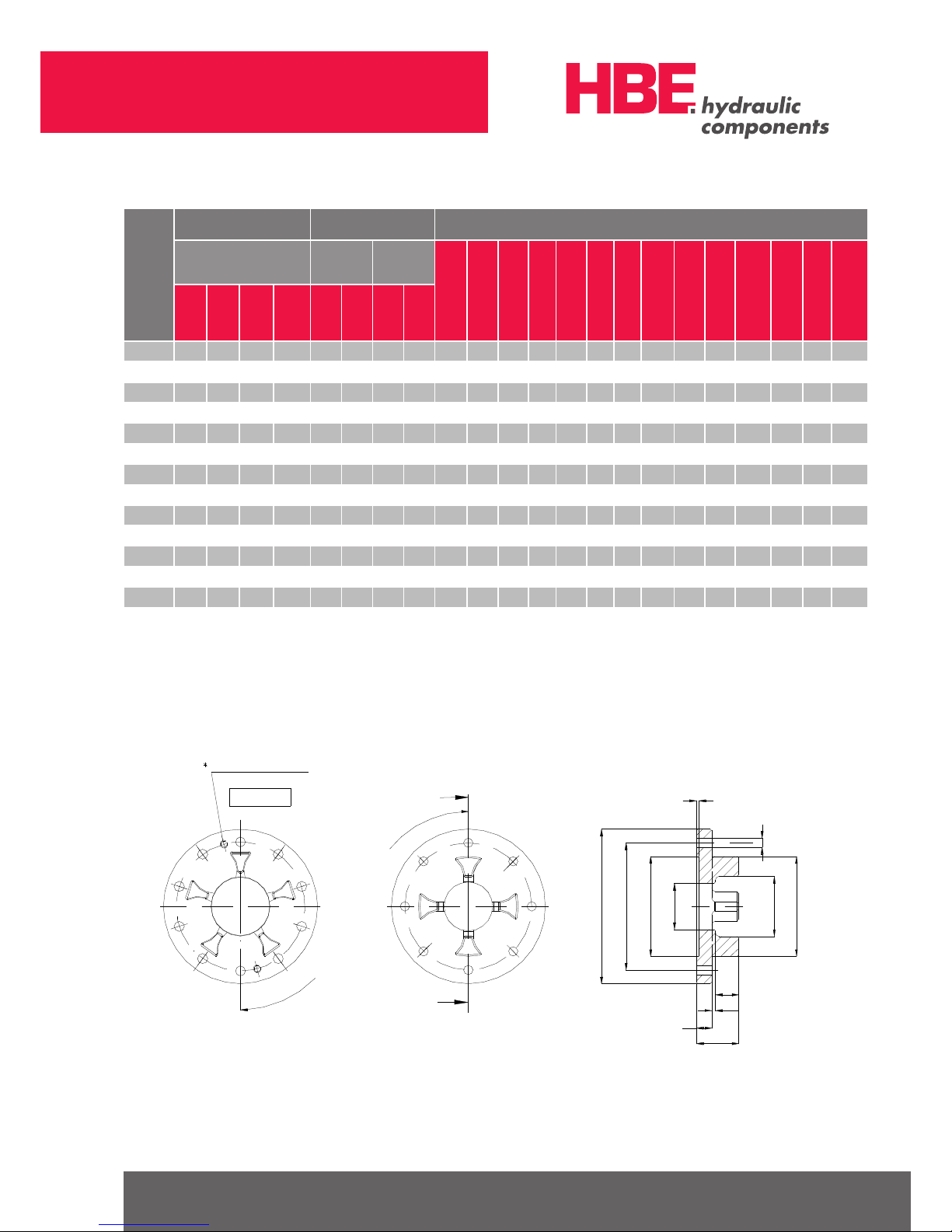
2. TECHNICAL DATA
E
b s
L
Zahnkranz
L 1
s
Nabe
A
G
L 2
Nabe
B
G
f 1
M
øA
øB
ød1
ødh
ød2
øB1
Hub
Hub
Gear Ring
Solutions for Fluid Technology
HBE GmbH
Hönnestraße 47 | 58809 Neuenrade | Germany
Phone +49 (0) 23 94 / 616-0
Fax +49 (0) 23 94 / 616-25
info@hbe-hydraulics.com
www.hbe-hydraulics.com
TYPE HARDNESSE S OF
GEAR RING
BORES DIMENSIONS
mm
NOMINAL TORQUE
Nm
FINISH
BORE
d 1
FINISH
BORE
d 2
A B B
1
L
L
1
+
L
2
E s b G dh g f f1 M
92 Sh A
95 Sh A
98 Sh A
64 Sh D
min
max
min
max
14/16 7. 5 - 12. 5 - - 4 16 30 - - 35 11 13 1.5 10 - 10 M4 5 5 M3
19/24 10 - 17 - - - 6 24 40 - - 66 25 16 2 12 - 18 M5 10 12 M6
24/30 35 - 60 75 - - 8 32 55 - - 78 30 18 2 14 - 27 M5 10 14 M8
28 / 38 95 - 160 200 - - 10 38 65 - - 90 35 20 2.5 15 - 30 M6 15 15 M8
38 / 45 190 - 325 405 14 38 40 45 80 66 78 11 4 45 24 3 18 37 38 M8 15 20 M10
42 / 5 5 265 - 450 560 16 42 45 55 95 75 93 126 50 26 3 20 40 46 M8 20 20 M10
48 / 60 310 - 525 655 19 48 50 60 105 85 103 140 56 28 3.5 21 45 51 M8 20 30 M10
5 5 / 70 375 - 625 825 22 55 60 70 120 98 118 160 65 30 4 22 52 60 M10 20 25 M12
6 5 / 75 625 900 - 117 5 25 65 70 75 135 115 132 185 75 35 4.5 26 59 68 M10 20 30 M12
75/90 975 150 0 - 2400 30 75 80 90 160 135 158 210 85 40 5 30 65 80 M10 25 30 M16
90/100 2400 3600 - 4500 - - 45 100 200 - 170 245 100 45 5.5 34 81 100 M10 25 30 M20
100/110 3300 4950 - - - - 45 11 0 225 - 18 0 270 110 50 6 38 89 113 M12 30 - -
110/125 4000 6000 - - - - 60 125 255 - 200 295 12 0 55 6.5 42 96 12 7 M16 35 - -
125/145 5000 750 0 - - - - 60 145 290 - 230 340 140 60 7 46 112 147 M16 40 - -
FLANGE HUB
b
L
l 1
s
l 2
90/100 FA
nur bei Ausführung
2x M12 durchgehend
Types 75/90 – 90/100 FA Types 28/ 38 – 65/75 FA
Z= Quantity øG
Z= Quantity øG
øA
øD1
øD2 H7
ød
øF
øA1
øG
2x M12 through only
in case of type

Solutions for Fluid Technology
HBE GmbH
Hönnestraße 47 | 58809 Neuenrade | Germany
Phone +49 (0) 23 94 / 616-0
Fax +49 (0) 23 94 / 616-25
info@hbe-hydraulics.com
www.hbe-hydraulics.com
TYPE
DIMENSIONS mm
A A
1
L L
1
s b F l
2
D
1
D
2
d G Z
28 / 38 FA 10 0 65 2 7.5 10 2.5 15 39 1.5 80 65 30 7 6
38 / 45 FA 115 80 31 10 3 18 48 1. 5 95 80 38 7 6
42/ 55 FA 140 95 35 12 3 20 57 2 115 95 46 9 6
48 / 60 FA 150 105 36.5 12 3.5 21 63 2 125 105 51 9 8
55 / 70 FA 175 120 42 16 4 22 74 2 145 120 60 11 8
65 / 75 FA 190 135 46.5 16 4.5 26 83 2 160 135 68 11 10
75 / 90 FA 215 160 54 19 5 30 98 2.5 18 5 16 0 80 14 10
90 / 100 FA 260 200 59.5 20 5.5 34 122 3 225 200 100 14 12
THREAD M6 M8 M10 M12
TORQUE Nm 14 35 69 12 0
3. INDICATIONS
3.1 GENERAL INDICATIONS
Before initial operation, the installation instructions must
be read carefully. Please pay attention to the security
and warning indications. The Softex® coupling is approved for application in hazardous areas.
Please pay special attention to the indications and
prescriptions concerning security (Item 6). This operating
and mounting instruction is part of the delivery extent and
must be kept carefully.
Tightening torque for the fixing screws DIN 912 – 10.9
3.2 WARNING AND INDICATION SIGNS
Passages with following indications must be especially
paid attention to.
DANGER ! Danger of injury for persons
ATTENTION! Engine trouble possible
INDICATION! Important items
CAUTION! Indications to protection in
hazardous areas
3.3 INDICATIONS OF RISKS
DANGER!
Due to the high risk of injury by rotating parts, you
must ensure that the complete system is protected
from accidental activation during mounting, service
and maintenance. Please imperatively pay attention
to the following safety information:
• During all activities with and at the coupling, please
especially pay attention to the safety regulations.
• Before starting the activities at the coupling, the power
unit must be switched off.
• The power unit must be protected from unintentional
switching on by labels or removing of the protector.
• The unintentional contact of a running coupling must be
prevented by appropriate safety devices.
• In case of operating couplings please pay attention to
a sufficient safety clearance.

Solutions for Fluid Technology
HBE GmbH
Hönnestraße 47 | 58809 Neuenrade | Germany
Phone +49 (0) 23 94 / 616-0
Fax +49 (0) 23 94 / 616-25
info@hbe-hydraulics.com
www.hbe-hydraulics.com
3.4 USAGE
The following items must be paid attention to before
mounting, operation or service of the coupling.
• The operating and mounting instructions are to be read
imperatively.
• Operations must only be made by qualified personnel.
The coupling must only be applied in accordance to its
corresponding technical data. Constructional changes of
the coupling parts without any permission by the manufacturer are illegal and result in loss of warrenty.
4. STORAGE
Due to the corrosion protection which must not be damaged, the coupling can be stored for approx. 6 – 12
months at a dry place.
The gear rings (Polyurethane) keep their qualities in case
of a corresponding storage for approx. 5 years.
ATTENTION!
It must be ensured that there is no condensation in
the storage rooms. A relative humidity of less than
65 % is favourable.
Furhtermore, please ensure that there are no ozone
generating devices, such as illuminants or high
voltage devices in the storage rooms.
5. MOUNTING
5.1 MOUNTING OF COUPLING
Basically, the coupling is supplied in component parts.
Before mounting, the coupling must be checked for completeness.
Distinguishing features of the gear rings (Item 2)
ITEM PIECES DENOMINATION
11 2 Hub
2 1 Gear Ring
3 2
Set screw or
Cheese head screw
SHORE HARDNESS
(SHORE)
MARKING
(COLOUR)
80 SH A blue
92 Sh A white
95/98 Sh A red
64 Sh D green
Gewindestift oder
Zahnkranz
1
A- Nabe
3
2
B-Nabe
3
1
bei Klemmnabe Zylinderschraube
A-Hub B-HubGear Ring
Set Screw or
Cheese head screw in case of Clamping Hub

Solutions for Fluid Technology
HBE GmbH
Hönnestraße 47 | 58809 Neuenrade | Germany
Phone +49 (0) 23 94 / 616-0
Fax +49 (0) 23 94 / 616-25
info@hbe-hydraulics.com
www.hbe-hydraulics.com
5.2 CHANGES OF COUPLING
DANGER!
A change at the coupling parts is only permitted
after having checked with the manufacturer.
For making the shaft bore by the user, please pay attention to the following items:
• The maximum admissible bore diameter d1 + d2 (see
Technical Data) must not be exceeded. In case of
disregard of these values, the coupling might break.
Flying fragments can cause serious personal injuries.
This concerns all materials.
• The predetermined planning and rotation accuracy of
the manufacturer must be adhered to.
• For making the finish bore, a careful alignment must be
made.
• For the axial safety device, please use a locking screw.
• If using a locking screw, following tightening torques
must be kept (see table):
5.3 MOUNTING
INDICATION!
Before mounting, we recommend to check the bores,
shaft, hub and feather key for accuracy.
A heating of the hubs to approx. 80°C eases the fitting
onto the shaft.
DANGER!
In order to avoid burnings by the contact with ted
hubs, please wear safety gloves.
CAUTION!
Please pay attention to the danger of ignition in
hazardous areas.
ATTENTION!
When mounting the coupling, please ensure that the
dimension E (see Technical Data) must absolutely be
kept, so that the gear ring is axially movable during
operation. Disregard might lead to damages.
• After mounting of the hubs to the shafts of the drive and
load side, the dimension “E” must be adjusted by relo cation of the aggregates or the hubs on the shafts.
• Shafts with inserted feather key and a smaller diameter
than the inner diameter of the gear ring dh may reach
into the gear ring. The distance between the shafts must
not be lower than 50% of the dimension “E”.
• For securing the hubs by relocation, please tighten the
locking screw with corresponding starting torque
(Table 5.3).
TYPE 14 19 24 28 38 42 48 55 65 75 90 100 110 12 5
THREAD M4 M5 M5 M6 M8 M8 M8 M10 M10 M10 M10 M12 M16 M16
TORQUE Nm 1.5 2 2 4,8 10 10 10 17 17 17 17 40 80 80
TYPE 14 19 24 28 38 42 48 55 65 75 90
THREAD M3 M6 M8 M8 M10 M10 M10 M12 M12 M16 M20
TORQUE Nm 1.34 10.5 25 25 60 60 60 10 0 100 250 490
Tightening torques of the locking screws
Tightening Torques of the locking screws for clamping hubs

Solutions for Fluid Technology
HBE GmbH
Hönnestraße 47 | 58809 Neuenrade | Germany
Phone +49 (0) 23 94 / 616-0
Fax +49 (0) 23 94 / 616-25
info@hbe-hydraulics.com
www.hbe-hydraulics.com
5.4 VALUES OF MISALIGNMENT
CAUTION!
During operation in hazardous areas, the ends of
the shaft must imperatively be aligned. Furthermore,
the durability of the coupling can be increased by
an exact alignment. Please keep the recommended
values of misalignment (see table).
Exceeding of the values will lead to damages on the
coupling. For operation in hazardous areas of explosion groups IIC (Designation II 2G c IIC T4), the
values must be reduced by 50%.
The values of the table are valid for an operating temperature T = +30°.
ATTENTION!
In case of an increase of the operating temperature,
the maximum permissible values of radial alignment
and misalignment of angle must be multiplied by the
temperature factor.
b
s s
Axial Misalignment Radial Misalignment Misalignment of Angle
TYPE DIMENSIONS
mm
AXIAL
MISALIGNMENT
∆KA
mm
RADIAL MISALIGNMENT ∆KR mmMISALIGNMENT OF ANGLE
∆KW
°
SPEED1 (1/MIN) SPEED1 N (1/MIN)
L E b s 750 1000 1500 3000 750 1000 150 0 3000
14/16 35 13 10 1.5 1.0 0.22 0.20 0.16 0 .11 1.1 1.1 0.9 0.8
19/24 66 16 12 2.0 1.2 0.27 0.24 0.20 0.13 1.1 1.1 0.9 0.8
24/30 78 18 14 2.0 1.4 0.30 0.27 0.22 0 .15 1.1 1.0 0.9 0.8
28 / 38 90 20 15 25 1.5 0.34 0.30 0.25 0.17 1.1 1.0 0.9 0.8
38 / 45 114 24 18 3.0 1.8 0.38 0.35 0.28 0.19 1.1 1.1 1.0 0.8
42 / 5 5 126 26 20 3.0 2.0 0.43 0.38 0.32 0 . 21 1.1 1.1 1.0 0.8
48 / 60 14 0 28 21 3.5 2.1 0.50 0.44 0.36 0.25 1.2 1.2 1.1 0.9
5 5 / 70 160 30 22 4.0 2.2 0.54 0.46 0.38 0.26 1.2 1.2 1.1 1.0
6 5 / 75 185 35 26 4.5 2.6 0.56 0.50 0.42 0.28 1. 2 1.2 1.2 1. 0
75/90 210 40 30 5.0 3.0 0.65 0. 58 0.48 0.32 1.3 1.2 1.2 1.0
90/100 245 45 34 5.5 3.4 0.68 0.60 0.50 0.34 1. 3 1.3 1.2 1.1
100/110 270 50 38 6.0 3.8 0. 71 0.64 0.52 0.36 1.3 1.3 1.2 1.1
110/125 295 55 42 6.5 4.2 0.75 0.67 0.55 0.38 1.3 1.3 1.3 1.1
125/145 340 60 46 7. 0 4.6 0.80 0.70 0.60 - 1.3 1.3 1.3 -

Solutions for Fluid Technology
HBE GmbH
Hönnestraße 47 | 58809 Neuenrade | Germany
Phone +49 (0) 23 94 / 616-0
Fax +49 (0) 23 94 / 616-25
info@hbe-hydraulics.com
www.hbe-hydraulics.com
TEMPERATURE -25°C < +30°C +40°C +60°C +80°C
FACTOR ST 1.0 0.8 0.7 0.6
EXPLOSION GROUP CONTROLLING INTERVALS
II 2G C IIB T4 X
II 2D C T 110°C X
I M2 C X
After an operating time of 3000 h, 6 months after initial operation of the coupling at the latest, the elastic gear ring
must be put to test (visual check, torsion test).
In case of an unessential or no wear of the gear ring during first check, the check cycles can be set to an operating time
of 6000 h or 18 months at the same operating conditions.
In case of an increased wear at first check, we recommend to proceed as followed:
• Exchange of the gear ring
• Determination of cause
• Adjustment of the check cycles to the operating conditions
II 2G C IIC T4 X
After an operating time of 2000 h, 3 months after initial operation of the coupling at the latest, the elastic gear ring
must be put to test (visual check, torsion test).
In case of an unessential or no wear of the gear ring during first check, the check cycles can be set to an operating time
of 4000 h or 12 months at the same operating conditions.
In case of an increased wear at first check, we recommend to proceed as followed:
• Exchange of the gear ring
• Determination of cause
• Adjustment of the check cycles to the operating conditions
5.4 VALUES OF MISALIGNMENT
The maximum admissible values of misalignment mentioned in the table must only be used proportionally in
case of parallel radial alignment and alignment of angle.
Example 1: Example 2:
∆KR = 20 % ∆KR = 60 %
∆KW = 80 % ∆KW = 40 %
∆K
totally
= ∆KR + ∆KW ≤ 100 %
6. USE IN HAZARDOUS LOCATIONS
6.1 INDICATIONS
CAUTION!
Concerning the explosion groups IIB and IIC, following materials are used by HBE:
Cast Iron (GG25, GG20) Stainless Steel (VA)
Spheroidal Cast Iron (GGG40) Sinter Steel (S)
Steel (St)
HBE does not use aluminium as material for the
couplings applied in hazardous areas.
6.2 CONTROLLING INTERVALS
90%80% 100%
30%
0
20%
10%
80%
50%
40%
70%
60%
100%
90%
70%
50%
60%
10%
20% 3 0%
40%
Misalignment of Angle ∆Kw
Radial Misalignment ∆Kr
Solutions for Fluid Technology
HBE GmbH
Hönnestraße 47 | 58809 Neuenrade | Germany
Phone +49 (0) 23 94 / 616-0
Fax +49 (0) 23 94 / 616-25
info@hbe-hydraulics.com
www.hbe-hydraulics.com
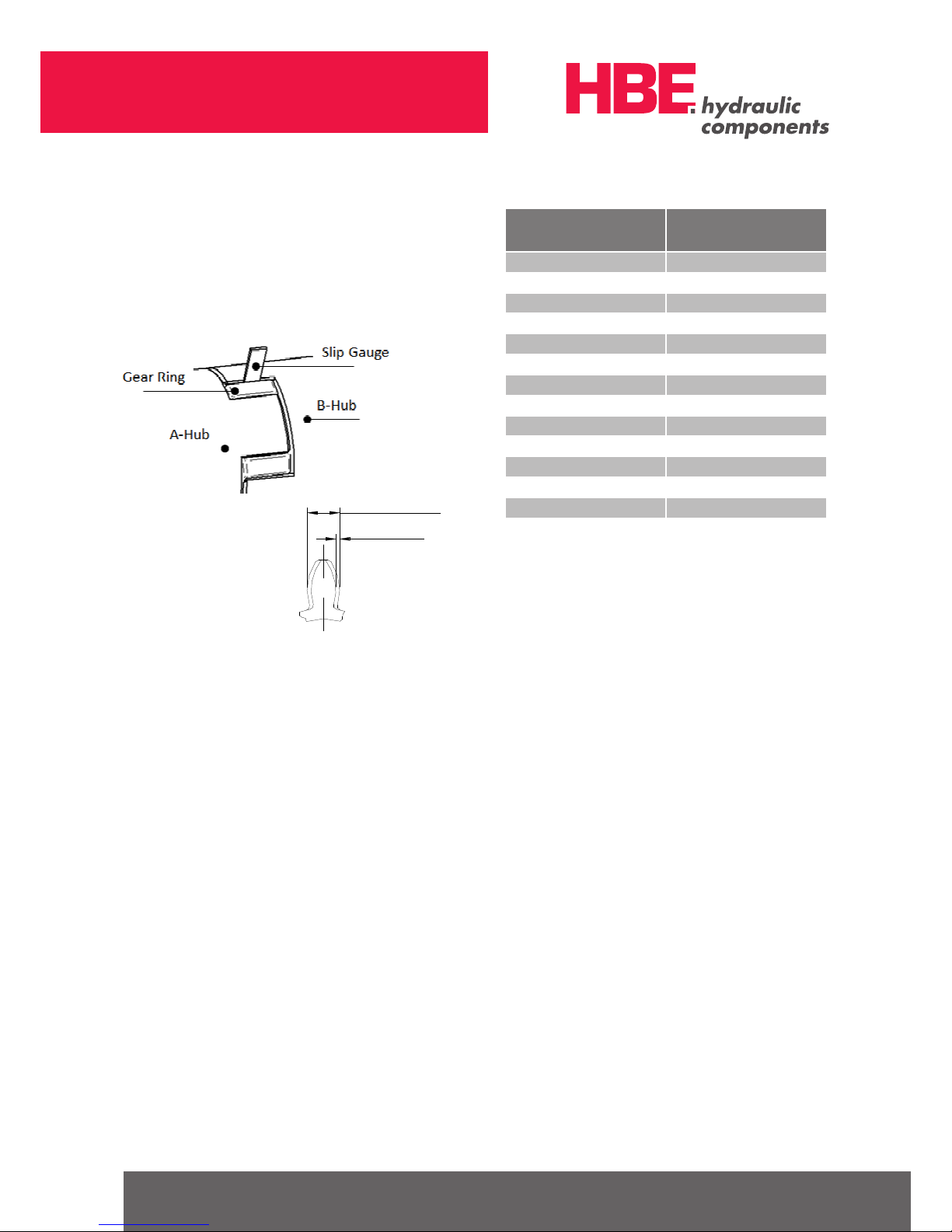
6.3 WEAR RATINGS
The check of the wear limit shall be made by a guide
between tooth flank and coupling claw.
In case of a backlash > X mm, the gear ring must be
exchanged.
6.4 IDENTIFICTION
Couplings for use in hazardous areas have to be marked
respectively for the permitted conditions of use.
Identification mark:
II 2G c IIB T4 X II 2G c IIC T4 X
II 2D c T 110°C X I M2 c X
The explosion groups IIB and IIA as well as the temperature ranges T3 – T1 are included in the identification
mark II 2G c IIC T4 X.
6.5 COMMISSIONING
Bevor commissioning of the coupling, following checks
and possible corrections must be made:
• Check of alignment
• Check of misalignment
• Check of distance dimension E
• Check of the tightness of the set screws in the hubs
• Check of the tightness of the fixing screws when using
flange hubs
CAUTION!
In hazardous areas, the set screws fixing the hubs
and the fixing screws of the flange hubs must be
secured against self-loosening, e.g. glue with Loctite
270.
TYPE WEAR LIMIT
X MAX .
mm
14/16 2
19/24 3
24/30 3
28 / 38 3
38 / 45 3
42 / 5 5 4
48 / 60 4
5 5 / 70 5
6 5 / 75 5
75/90 6
90/100 8
100/110 9
110/125 9
125/145 10
New condition
X = Wear

Solutions for Fluid Technology
HBE GmbH
Hönnestraße 47 | 58809 Neuenrade | Germany
Phone +49 (0) 23 94 / 616-0
Fax +49 (0) 23 94 / 616-25
info@hbe-hydraulics.com
www.hbe-hydraulics.com
Afterwards, the user has to fit a coupling protection consisting of a fixed cover. The cover is intended to protect
the coupling especially from falling items. The covers can
be provided with regular openings. Following dimensions
must not be exceeded.
The distance of the cover to rotating parts must be at
least 5 mm. The cover must be electrically conductive and
must be included in the potential equalisation. The cover
is only allowed to be taken off during a halt. Aluminium
bellhousings (also with damping flange) are permitted as
connecting element, if the content of magnesium is less
than 7.5 %.
CAUTION!
When mounting the coupling to machines of category 2D, please ensure that there is no dust between cover and coupling. The couplings must not
operate in dust particles. When using the coupling
in machines of group I, category M2, the cover must
not consist of light metal (higher mechanical load).
During operation of the coupling please pay attention to:
• Changed operation noises
• Occurring vibrations
ATTENTION!
In case of changes or irregularities during the operation of the coupling, the power unit must be switched
off immediately. The cause of the disturbance must
be found out by the check list ”Trouble in service”
and be removed, if possible.
ROUND
OPENINGS
Ø
mm
RECTANGULAR
OPENINGS
SIDE LE NGTH
mm
TOP OF COVER
4 4
SIDE OF COVER
8 8
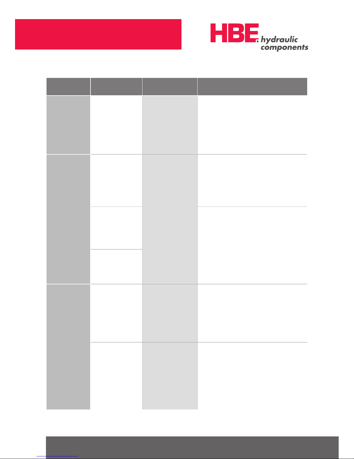
6.6 TROUBLE IN SERVICE / CAUSES AND CLEARANCE
A disturbance by break of the fixing screws of the flange
couplings must be excluded under observance of the
selection criteria.
DISTURBANCES CAUSES INDICATIONS OF
RISKS FOR HAZARDOUS
AREAS
CLEARANCE
Changes of
running noises
Vibrations
Alignment fault
High temperatures
at the sur face lead to
an ignition risk
• Stop the unit
• Check and remove changes in construction
• Check the drive unit for damages
• Check and correct, if necessary, alignment and dimension
E of the coupling
• Check the wear of the gear ring and exchange,
if necessary
Loose screws for axial
securing of the hub
Ignition risk by hot surface
and sparking
• Stop the unit
• Check and correct alignment and dimension E of the
coupling
• Check the wear of the gear ring and exchange,
if necessary
• Retighten the fixing screws by the starting torque and
protect it from self-loosening with Loctite
Solutions for Fluid Technology
HBE GmbH
Hönnestraße 47 | 58809 Neuenrade | Germany
Phone +49 (0) 23 94 / 616-0
Fax +49 (0) 23 94 / 616-25
info@hbe-hydraulics.com
www.hbe-hydraulics.com
DISTURBANCES CAUSES INDICATIONS OF
RISKS FOR HAZARDOUS
AREAS
CLEARANCE
Changes of
running noises
Vibrations
Wear of gear ring
Short-term torque transfer
by metal contact
Ignition risk by sparking
• Stop the unit
• Dismount the coupling
• Remove the gear ring
• Check the parts of the coupling and exchange damaged
parts
• Renew the gear ring
• Check and, if necessary, correct the alignment
• Tighten the fixing screws with tightening torque and protect
it from self-loosening with Loctite
Break of
claw
Blockage and overload
rupture of claws by
operating errors
Ignition risk by sparking
due to metal contact of
the claws
• Stop the unit
• Dismount the coupling
• Check the shafts and feather keys for damages
• Check the drive unit for damages
• Mount the complete coupling
• Check the alignment
• Tighten the fixing screws with tightening torque and
protect it from self-loosening by Loctite
The parameters for the
determination of the
coupling do not correspond
to the actual operation
conditions. Dimensions of
coupling too small.
• Stop the unit
• Dismount the coupling
• Check the shafts and feather keys for damages
• Check the operating parameter and choose a harder gear
ring or bigger coupling
• Check the mounting space when deciding for a bigger
coupling
• Mount the complete coupling
• Check and correct, if necessary, alignment and dimension
E of the coupling
• Tighten the fixing screws with tightening torque and
protect it from self-loosening with Loctite
Increased wear of gear ring
Claws smash during torque
transfer
Premature wear
of gear ring
Error of alignment
Dimension E
was not kept
Ignition risk by high
temperatures at the
gear ring
• Stop the unit
• Check the mounting and remove errors of alignment
• Check the parts of the coupling and exchange damaged
parts
• Exchange the gear ring
• Check and correct, if necessary, alignment and dimension
E of the coupling
• Tighten the fixing screws with tightening torque and
protect it from self-loosening with Loctite
Torsional vibrations
destroy the charged teeth
inside
Ignition risk by sparking
during metal contact of the
claws
• Stop the unit
• Check the parts of the coupling and exchange damaged
parts
• Find out and remove cause of vibration
• Exchange the gear ring (eventually choose smaller or
higher shore hardness, please pay attention to the size of
the coupling)
• Check and correct, if necessary, alignment and dimension
E of the coupling
• Tighten the fixing screws with tightening torque and
protect it from self-loosening with Loctite

Solutions for Fluid Technology
HBE GmbH
Hönnestraße 47 | 58809 Neuenrade | Germany
Phone +49 (0) 23 94 / 616-0
Fax +49 (0) 23 94 / 616-25
info@hbe-hydraulics.com
www.hbe-hydraulics.com
DISTURBANCES CAUSES INDICATIONS OF
RISKS FOR HAZARDOUS
AREAS
CLEARANCE
Premature wear
of gear ring
Inadmissibly high
temperatures by contact
heating
Ignition risk by sparking
during metal contact of
the claws
• Stop the unit
• Check the parts of the coupling and exchange damaged
parts
• Find out and remove the source of heat
• Exchange the gear ring
• Check and correct, if necessary, alignment and dimension
E of the coupling
• Tighten the fixing screws with tightening torque and protect
it from self-loosening with Loctite
Aggressive environmental
conditions
(vapours, chemicals, etc.)
and/or liquids (bio oils)
• Stop the unit
• Check the parts of the coupling and exchange damaged
parts
• Check and correct the environmental conditions
• Check the operating medium and change, if possible
• Exchange the gear ring
• Check and correct, if necessary, alignment and dimension
E of the coupling
• Tighten the fixing screws with tightening torque and protect
it from self-loosening with Loctite

Solutions for Fluid Technology
H04 0 09 4a 09/17 www.plakar t.de
www.e-holding.de
HBE GmbH
Hönnestraße 47 | 58809 Neuenrade | Germany
Phone +49 (0) 23 94 / 616-0
Fax +49 (0) 23 94 / 616-25
info@hbe-hydraulics.com
www.hbe-hydraulics.com
6.7 DECLARATION OF CONFORMITY
DECLARATION OF CONFORMITY
According to the EG rules 94/9/EG dated 23 rd March, 1994 and the legal requirements
the manufacturer
HBE GmbH
Hönnestr. 47
58809 Neuenrade/Germany
hereby declares that the following products described in the operation and mounting instructions
Softex
®
– Elastic Couplings,
are non-electric devices acc. to the EG rules 94/9/EG and meet the security and healthy prescriptions for the conception and
the construction of the device concerning the intended use in hazardous locations as stated in subjoinder II of the guide. A
conformity to the norms EN 1127-1: 2011; EN 1127-2: 2002; EN 12463-1: 2009 and EN 13463-5: 2011 is given.
Following test certifi cate of type is existing for the Softex® – Elastic Couplings:
IBExU04ATEXB027 X
Acc. to RL 94/9/EG the technical documentation is deposited at the following place:
IBExU
Institut für Sicherheitstechnik GmbH
Fuchsmühlenweg 7
D-09599 Freiberg
Neuenrade, 14.11.14 i.V.
Date Detlef Lengelsen Holger Anton
Managing Director QS- Manager
 Loading...