

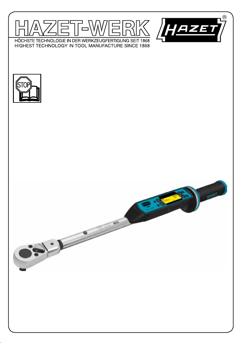
SYSTEM 7000 eTAC
Betriebsanleitung
Elektronischer Drehmoment-/Drehwinkel-Schlüssel
Operating Instructions
Electronic torque wrench with built-in angle gauge
7292-eTAC
223717
1

. . . . . . . . . . . . . . . . . . . . . . . . . . . . . . . . . . .3 – 14
Kurzanleitung
. . . . . . . . . . . . . . . . . . . . . . . . . . . . . 8
. . . . . . . . . . . . . . . . . . . . . . . . . . . . . . . . . . 15– 26
Quick start guide . . . . . . . . . . . . . . . . . . . . . . . . . . . 20
Ursprungsprache deutsch – original language: German – Langue d’origine: allemand
HAZET-WERK – Hermann Zerver GmbH & Co. KG • } 10 04 61 • D-42804 Remscheid • Germany
[ +49 (0) 21 91 / 7 92-0 • \ +49 (0) 21 91 / 7 92-375 (Deutschland) -400 (International)
^ hazet.de • ] info@hazet.de
2
a
Zu Ihrer Information
1. Allgemeine Informationen
Der Drehmoment-/Drehwinkel-Schlüssel
wurde für das kontrollierte Anziehen und
Lösen von Schraubverbindungen mit Rechtsoder Linksgewinde entwickelt.
Jeder HAZET-Drehmoment-/Drehwinkel-Schlüssel wird
für das Drehmoment nach DIN EN ISO 6789 und für
den Drehwinkel nach Werksvorgaben kalibriert und
mit Seriennummer, Betriebsanleitung und Zertifikaten
ausgeliefert.
Zum bestimmungsgemäßen Gebrauch des
Drehmoment- / Drehwinkel-Schlüssels gehört die
vollständige Beachtung aller Sicherheitshinweise und
Informationen in dieser Betriebsanleitung. Nur so ist
ein langfristiger und störungsfreier Einsatz dieses
Präzisionswerkzeuges gewährleistet.
Bewahren Sie diese Betriebsanleitung immer bei Ihrem
HAZET-Werkzeug auf.
ACHTUNG: Beachten Sie alle Sicherheits-, Warn- und
Bedienungshinweise für den sicheren und störungs
freien Betrieb des Werkzeuges und zur Abwendung
unmittelbarer Gefahren. Schenken Sie den folgenden
Symbolen höchste Aufmerksamkeit.
2. Symbolerklärung
BETRIEBSANLEITUNG LESEN!
Der Betreiber ist verpflichtet die
Betriebsanleitung zu beachten und alle
Anwender des Werkzeugs gemäß der
Betriebs anleitung zu unterweisen.
HINWEIS!
Dieses Symbol kennzeichnet Hinweise, die
Ihnen die Handhabung erleichtern.
WARNUNG!
ACHTUNG!
-
NUR FACHLEUTE!
Dieses Symbol kennzeichnet wichtige
Beschreibungen, gefährliche Bedin gungen,
Sicherheitsgefahren bzw.
Sicherheitshinweise.
Dieses Symbol kennzeichnet Hin wei se, deren
Nichtbeachtung Be schä digungen,
Fehlfunktionen und/ oder den Ausfall des
Gerätes zur Folge haben.
Werkzeug nur für die Verwendung durch
Fachleute geeignet, Handhabung durch Laien
kann zu Verletzungen oder Zerstörung des
Werkzeugs oder des Werkstücks führen.
3
Zu Ihrer Sicherheit
1. Allgemeines
ACHTUNG! Für den Gebrauch und die Reparatur
des Gerätes ist besonderes Fachwissen und /
oder eine geeignete Ausbildung erforderlich.
Das Gerät ist zum Zeitpunkt seiner Entwicklung
und Fertigung nach geltenden, anerkannten Regeln
der Technik gebaut und gilt als betriebssicher. Vom
Werkzeug können jedoch Gefahren ausgehen, wenn es
von nicht fachgerecht ausgebildetem Personal, unsach
gemäß oder nicht bestimmungsgemäß verwendet wird.
Jede Person, die mit Arbeiten am oder mit dem Gerät
beauftragt ist, muss daher die Betriebsanleitung vor
Beginn der Arbeiten gelesen und verstanden haben.
2. Verantwortung des Betreibers
• Bewahren Sie die Betriebsanleitung stets in unmittelbarer Nähe des Werkzeuges auf. Sollte die
Betriebsanleitung verloren gegangen oder unbrauch
bar geworden sein, wenden Sie sich bitte an Ihren
Fachhändler oder an das HAZET-Service-Center.
• Vor jeder Benutzung ist der Drehmoment-/DrehwinkelSchlüssel auf seine volle Funktionsfähigkeit zu prü
fen. Ist die Funktionsfähigkeit nach dem Ergebnis
dieser Prüfung nicht gewährleistet oder werden
Schäden festgestellt, darf das Werkzeug nicht ver
wendet werden. Ist die volle Funktionsfähigkeit nicht
gegeben und das Werkzeug wird dennoch verwen
det, besteht die Gefahr von erheblichen Körper-,
Gesundheits- und Sachschäden.
• Betreiben Sie den Drehmoment-/DrehwinkelSchlüssel nur in technisch einwandfreiem Zustand.
Wenn das Gerät nicht einwandfrei arbeitet, ist es
außer Betrieb zu nehmen und zu überprüfen.
• Alle Sicherheits-, Warn- und Bedienungshinweise am
Gerät sind zu beachten und stets in gut lesbarem
Zustand zu halten. Beschädigte Beschriftungen,
Schilder oder Aufkleber, sowie die DisplayAbdeckung müssen sofort erneuert werden.
• Neben den Arbeitssicherheits-Hinweisen in der
Betriebsanleitung sind die für den Einsatz des
Werkzeuges allgemein gültigen Sicherheits-,
Unfallverhütungs- und Umweltschutzvorschriften zu
beachten und einzuhalten.
• Sicherheitseinrichtungen immer frei erreichbar vor
halten und regelmäßig prüfen.
• Machen Sie sich vor der Anwendung mit der
Bedienung des Drehmoment-/Drehwinkel-Schlüssels
vertraut und trainieren Sie den Umgang mit dem
Werkzeug. Prüfen Sie vor Gebrauch sorgfältig, ob
alle programmierten Einstellungen korrekt sind. Von
den Einstellungen ist die Qualität Ihrer Schraubarbeit
abhängig.
3. Bestimmungsgemäße
Verwendung
• Die Betriebssicherheit ist nur bei bestimmungsgemäßer Verwendung entsprechend den Angaben in
der Betriebsanleitung gewährleistet. Jede über die
bestimmungsgemäße Verwendung hinausgehende
und / oder andersartige Verwendung des Gerätes
ist untersagt und gilt als nicht bestimmungsgemäß.
• Die Benutzung, Inspektion und Wartung von Werkzeugen
muss immer entsprechend den lokalen staatlichen
Landes- oder Bundesbestimmungen erfolgen.
-
• HAZET-Drehmoment-/Drehwinkel-Schlüssel sind
ausschließlich zum kontrollierten Anziehen und
Lösen von Schraubverbindungen konzipiert.
• Der Einsatz als Hebel-, Klemm- oder Schlagwerkzeug
ist auf keinen Fall vorgesehen. Der unsachgemäße
Gebrauch, der Gebrauch unter Nichtbeachtung der
Sicherheitshinweise oder Überlastung des HAZETDrehmoment-Drehwinkel-Schlüssels kann zu fal
schen Messwerten und / oder zum Ausfall des
Systems und somit bis zum Tode, zu schweren
-
Körper-Gesundheits- und zu Sachschäden führen.
• Drehmoment-/Drehwinkel-Schlüssel sind kalibrierte
Messwerkzeuge und entsprechend pfleglich zu
behandeln. Vermeiden Sie deshalb mechanische,
-
chemische oder thermische Einwir kung en, die über
die Beanspruchungen des be stim mungs gemäßen
Gebrauchs hinausgehen. Der Drehmoment-/
-
Drehwinkel-Schlüssel darf weder Regen, noch
Feuchtigkeit ausgesetzt oder in Flüssigkeiten
-
getaucht werden. Lassen Sie keine Fremdkörper ein
dringen und decken Sie unbenutzte Buchsen immer
ab. Extreme klimatische Bedingungen wie Kälte, Hitze
und Luftfeuchtigkeit können die Messwerte bzw.
Messergebnisse beeinflussen. Bei Nichtbeachtung
können Sie den Drehmoment-/Drehwinkel-Schlüssel
beschädigen oder zerstören.
• Der unsachgemäße Gebrauch der enthaltenen
Werkzeuge oder der Gebrauch nicht entspre
chend der Sicherheitshinweise kann zu schweren
Verletzungen führen.
• Jede über die bestimmungsgemäße Verwen dung
hinausgehende und/oder andersartige Verwen dung
des Werkzeuges ist untersagt und gilt als nicht
bestimmungsgemäß.
• Prüfen Sie vor Gebrauch den sicheren Sitz des ver
wendeten Einsatzes und/oder Einsteck-Werkzeugs.
Setzen Sie das Werk zeug so an, dass es nicht von
der Schraub verbindung abrutschen kann. Andernfalls besteht die Gefahr von Personen- und/oder
Sachschäden.
• Bei der Verwendung von Einsätzen bzw. EinsteckWerkzeugen beachten Sie unbedingt deren norm
gerechte Ausführung sowie die richtige Form und
Größe für die Verbindung mit der anzuziehenden
Verschraubung.
-
-
-
-
-
4
Zu Ihrer Sicherheit
• Ebenfalls zu beachten ist die maximal zulässige Belastung des verwendeten Einsatzes oder
Einsteck-Werkzeugs. Diese kann niedriger sein als
das erreichbare Auslösemoment des Drehmoment-/
Drehwinkel-Schlüssels. Der Einsatz selbst gefertigter
Spezialwerkzeuge kann eine Gefah ren quelle darstel
len. Nichtbeachtung kann zu Personen- und/oder
Sachschäden führen.
• Ansprüche jeglicher Art gegen den Hersteller und/
oder seine Bevollmächtigten, wegen Schäden
aus nicht bestimmungsgemäßer Verwendung des
Werkzeuges, sind ausgeschlossen.
• Für alle Schäden, bei nicht bestimmungsgemäßer
Verwendung, haftet allein der Betreiber.
4. Gefahren, die vom Gerät
ausgehen
• Nehmen Sie keine Veränderungen am Werkzeug
vor. Aus Sicherheitsgründen sind Veränderungen
jeglicher Art sowie An- oder Umbauten am
Drehmoment-/Drehwinkel-Schlüssel untersagt.
Schutzvorrichtungen und / oder Gehäuseteile dürfen
nicht entfernt werden. Betätigen Sie das Werkzeug
nie, wenn eine Schutzabdeckung fehlt oder wenn
nicht alle Sicherheitseinrichtungen vorhanden und in
einwandfreiem Zustand sind.
• Das maximal zulässige Drehmoment darf in bei
den Betätigungsrichtungen nicht überschritten werden. Angegebene Grenzwerte, Einstellwerte und
Einstellbereiche sind unbedingt einzuhalten.
• Achten Sie auf einen sicheren Stand
• Die Werkzeuge nur an Orten verwenden, die durch
geltende Verordnungen für Arbeitsbereiche bestimmt
und vorgeschrieben werden.
ACHTUNG! Nicht in explosionsgefährdeten
Bereichen einsetzen
-
-
• Ansprüche jeglicher Art gegen den Hersteller und
/ oder seine Bevollmächtigten durch Schäden
aus nicht bestimmungsgemäßer Verwendung des
Gerätes sind ausgeschlossen. Die Vornahme von
Veränderungen am Gerät und / oder der nicht
bestimmungsgemäße Gebrauch führt zum sofortigen
Haftungsausschluss. Für alle Schäden, bei nicht
bestimmungsgemäßer Verwendung, haftet allein der
Betreiber.
5
Aufbau und Funktion
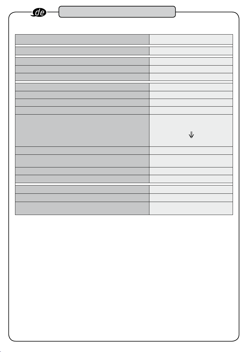
1. Technische Daten / Geräte-Elemente:
Technische Beschreibung
HAZET-No. 7292 eTAC
Drehmoment-Anzeigebereich (Nm): 5 – 200
Drehmoment-Messbereich (Nm): 10 – 200
Drehmoment-Einheit Nm
Relative Mess-Unsicherheit für Drehmoment-Messbereich ± 2 % / ± 1 Digit
Toleranzbereich Drehmoment ± 8 %
Drehwinkel-Messbereich (addierend) 5° bis 995°
Relative Mess-Unsicherheit für Drehwinkel-Messbereich ± 2 % / ± 1°
Toleranzbereich Drehwinkel
Einsteck-Vierkant (mm): 14 x 18
Justiert mit Einsteck-Werkzeug
Wirklänge (Wl) / Stichmaß lw (mm):
Länge mit / ohne Einsteck-Werkzeug (mm): 580 / 518
Gewicht mit / ohne Einsteck-Werkzeug (kg): 1,25 / 0,98
Menüsprachen: Piktogramme
Schutzklasse: IP 40
Batterien:
4 x 1,5 Volt AA (Mignon) oder
Akkus 4 x 1,2 Volt AA Mignon
Version
5° - 15° = ± 1°
20° - 25° = ± 2°
30° - 35° = ± 3°
ab 90° = ± 10°
6404-1 3
38,5
2. Lieferumfang:
• Drehmoment-/Drehwinkel-Schlüssel mit
Betriebsanleitung, Prüfzertifikat, Batterien,
Einsteck-Umschaltknarre gemäß o.g. Tabelle, in
Schutzverpackung.
6
Aufbau und Funktion
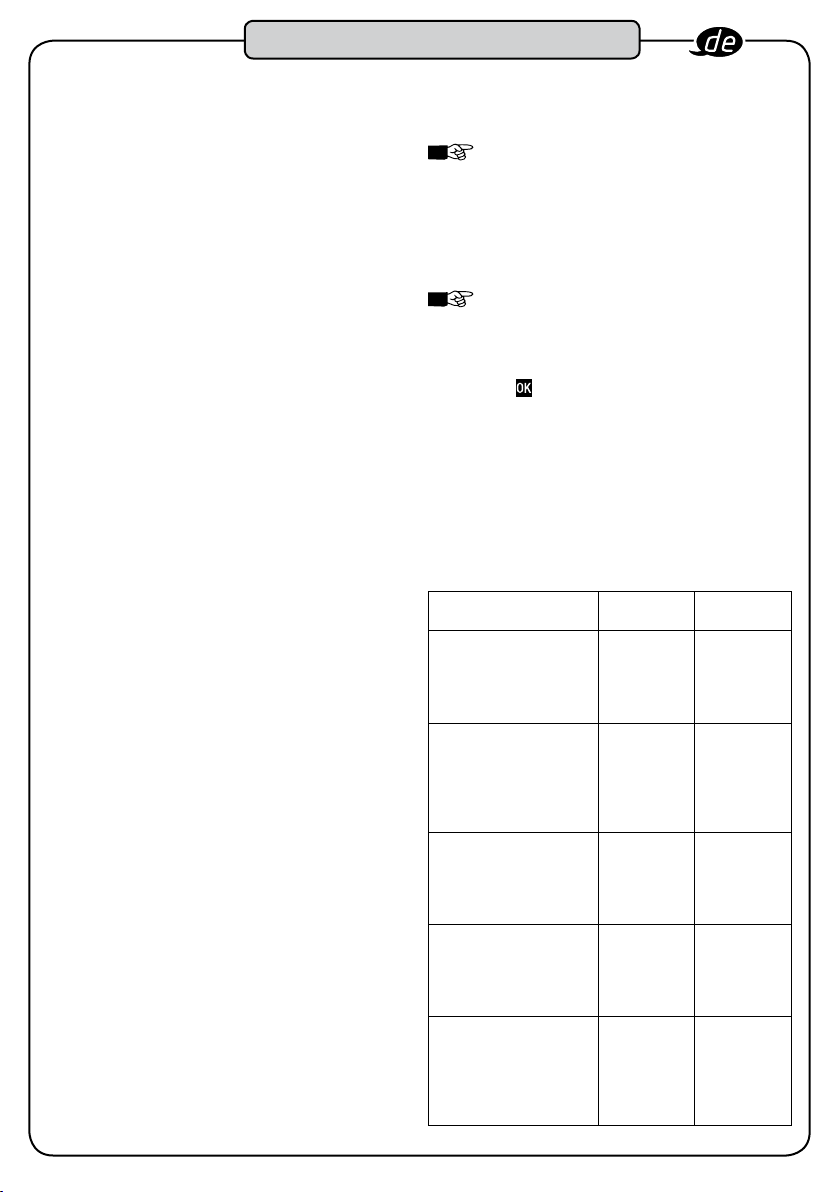
3. Funktionsweise / Signalstufen
• Der Drehmoment-/Drehwinkel-Schlüssel verfügt über
vier Signalstufen aus kombinierten sicht-, hör- und
fühlbaren Signalen, die beim Erreichen eingestellter
Werte ansprechen.
• Die sichtbaren Signale erscheinen unter dem mattie
ren Ring am Handgriff, die hörbaren Signale werden
durch einen Summer im Gehäuse und die fühl
baren Signale werden durch einen Vibrationsmotor im
Handgriff erzeugt.
• Der Drehmoment-/Drehwinkel-Schlüssel verfügt über
zwei Modi: „Drehmoment“ und „Drehwinkel“ (Nm/°).
• Das Erreichen des Fügemomentes und damit der
Beginn der Drehwinkelmessung wird durch ein ein
maliges gelbes Blinklicht angezeigt.
• Die erste Signalstufe mit gelbem Blinklicht, Signalton
und Vibration mit niedriger Frequenz, beginnt, wenn
das aufgebrachte Drehmoment bzw. der aufge
brachte Drehwinkel 80% des Zielwertebereichs
erreicht. Wenn die erste Signalstufe erreicht ist,
sollten Sie die Anzugsgeschwindigkeit verringern
und erhöhte Aufmerksamkeit auf Ihre Krafteinleitung,
die Anzeige und die Signale des Drehmoment-/
Drehwinkel-Schlüssels richten. Je kleiner der
Zielwert ist, desto schneller ist die erste Signalstufe
überschritten.
• Die zweite Signalstufe mit grünem Blinklicht,
Signalton und Vibration mit mittlerer Frequenz,
zeigt an, dass sich das aufgebrachte Drehmoment
bzw. der aufgebrachte Drehwinkel innerhalb des
Zielwertbereiches befindet. Ist die zweite Signalstufe
erreicht, ist der Schraubvorgang in diesem Bereich
zu beenden. Je kleiner der Zielwert ist, desto schnel
ler ist die zweite Signalstufe überschritten.
• Die dritte Signalstufe mit rotem Blinklicht, Signalton
und Vibration mit hoher Frequenz, zeigt an, dass sich
das aufgebrachte Drehmoment bzw. der aufgebrachte
Drehwinkel oberhalb des Zielwertbereiches befindet.
Ist die dritte Signalstufe erreicht, ist das aufgebrachte
Drehmoment bzw. der aufgebrachte Drehwinkel zu
hoch. Beenden Sie den Schraubvorgang. Verfahren
Sie entsprechend den Anweisungen für diesen
Schraubfall: z.B. Schraube lösen und erneut anziehen
oder durch eine neue Schraube ersetzen.
• Die vierte Signalstufe mit rotem Dauerlicht, DauerSignalton und Dauervibration, zeigt an, dass sich das
aufgebrachte Drehmoment oberhalb des maximal
zulässigen Drehmomentbereiches des Drehmoment-/
Drehwinkel-Schlüssels befindet. Erreichen Sie die
vierte Signalstufe, müssen Sie den Schraubvorgang
sofort abbrechen. Bei Nichtbeachtung können Sie
den Drehmoment-/Drehwinkel-Schlüssel beschädi
gen oder zerstören.
• Wird nach einer Betätigung kein Drehmoment oder
Drehwinkel mehr aufgebracht, wird der höchste Wert
dieses Vorganges im Wechsel mit einer i.O. - oder
n.i.O.- Bewertung im Display angezeigt.
• Der Drehmoment-/Drehwinkel-Schlüssel kann in
Drehrichtung Rechts (+) und Drehrichtung Links (-)
programmiert werden.
HINWEIS!
Schraubvorgang nach 2 Sekunden abgeschlos
-
-
-
-
sen, insofern innerhalb dieses Zeitraumes kein
Drehmoment aufgebracht wird. Im Modus
„Drehwinkel“ ist der Schraubvorgang nach
4 Sekunden abgeschlossen, insofern innerhalb
dieses Zeitraumes kein Drehwinkel aufgebracht
wird.
HINWEIS!
Schraubvorganges wird der jeweilige Endwert
(Drehmoment / Drehwinkel) im Wechsel mit der
i.O. oder n.i.O Bewertung angezeigt.
Nur nach Bestätigung des Schraubvorganges
mit
durchgeführt werden.
• Um die Anzeige des Displays, unabhängig von der
Betätigungsrichtung oder Handhabung gut ablesen
zu können, kann diese durch Tastendruck gedreht
werden.
• Wenn der Drehmoment-/Drehwinkel-Schlüssel
nicht benutzt wird, schaltet sich der Schlüssel nach
5 Minuten selbständig aus.
Im Modus „Drehmomente“ ist der
Nach Beendigung des
kann der nächste Schraubvorgang
Tabelle Signale:
Signalstufen Drehmoment Drehwinkel
Stufe 1 (Schwellwert)
gelbes Blinklicht
Signalton und
-
Vibration niedrige
Frequenz
Stufe 2 (innerhalb
Zielwertbereich)
grünes Blinklicht,
Signalton und
Vibration mittlere
Frequenz
Stufe 3 (oberhalb
Zielwertbereich)
rotes Blinklicht,
Signalton und
Vibration hohe Frequenz
Stufe 4 (oberhalb max.
Drehmoment)
rotes Dauerlicht
Dauersignal und
Dauervibration
Einmaliges gelbes
-
Blinklicht
beim Erreichen des
Fügemomentes =
Beginn der
Winkelmessung
v v
v v
v v
v v
-
v
7
Aufbau und Funktion
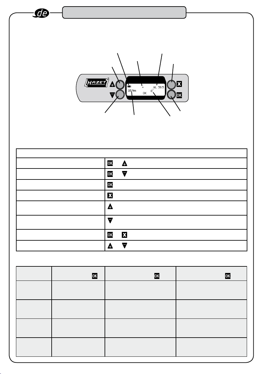
4. Display / Bedienfeld / Kurzanleitung
Tastenbelegung / Kurzanleitung
Einschalten
Ausschalten
Bestätigen
Menü öffnen / Menü schließen
Im Menü aufwärts gehen /
Zahlenwerte aufwärts wählen
Im Menü abwärts gehen /
Zahlenwerte abwärts wählen
Hinweise bestätigen
Display drehen
5. Menüstruktur
1. Ebene
- wechseln mit
1.
- wechseln mit
+ / –
2.
- wechseln mit
+ / –
3.
- wechseln mit
+ / –
4.
- wechseln mit
+ / –
Nm / ° Drehmoment Drehwinkel
Batterie-Anzeige
Drehrichtung
Pfeil +
eTAC
Made in Germany
Pfeil -
Drehmoment-Zielwert
bzw. Fügemoment
und 2x kurz gleichzeitig drücken und loslassen
und 1x kurz gleichzeitig drücken und loslassen
und gleichzeitig drücken
und gleichzeitig drücken
2. Ebene
WL Wirklänge
+/–
PC
- wechseln mit
Rechts (+)
Links (–))
Anzeige der Software-Version
Anzahl Auslösungen
Wirklänge
Drehwinkel
x
OK
3. Ebene
- wechseln mit
• • •
PC-Verbindung
(nur werkseitig nutzbar)
8
Aufbau und Funktion
6. Vor Inbetriebnahme:
Die Benutzung, Inspektion und Wartung
von Werkzeugen muss immer entspre
chend den lokalen, staatlichen Landesoder Bundesbestimmungen folgen.
Um Fehler in der Kraftübertragung zu vermeiden,
benutzen Sie möglichst keine Gelenkverbindungen
oder Verlängerungen. Bei der Verwendung
von Gelenkverbindungen kann das auf die
Schraubverbindung abgegebene Drehmoment wesent
lich verändert werden.
Achten Sie auf den sicheren Sitz des verwendeten
Einsteckwerkzeuges, der Steckschlüsseleinsätze oder
sonstigem Zubehör. Achten Sie bei der Verwendung
von Umschaltknarren auf die Einstellung der gewünsch
ten Drehrichtung. Der Hebel am Kopf der EinsteckUmschaltknarre schaltet die Knarre zwischen Rechtsund Links- Betrieb um.
Bei der Verwendung von Einsätzen beachten Sie unbe
dingt die normgerechte Ausführung, sowie deren richtige
Form und Größe zur Verbindung mit der Verschraubung.
Beachten Sie ebenfalls die maximal zulässige Belastung
des verwendeten Einsatzes. Diese kann niedriger sein
als das erreichbare Drehmoment des Drehmoment-/
Drehwinkel-Schlüssels. Der Einsatz veränderter
Werkzeuge oder selbst gefertigter Spezialwerkzeuge
stellt eine Gefahrenquelle dar. Verwenden Sie keine
verschlissenen oder beschädigten Werkzeuge oder
Einsätze. Nichtbeachtung kann zu Personen- und / oder
Sachschäden führen.
Setzen Sie das Werkzeug so an, dass es nicht von
der Schraubverbindung abrutschen kann. Achten Sie
auf einen sicheren Stand während der Betätigung.
Andernfalls besteht die Gefahr von Personen- und / oder
Sachschäden.
Das Lösen von Schraubverbindungen ist möglich.
Überschreiten Sie dabei aber keinesfalls das maximale
Drehmoment des Drehmoment-/Drehwinkel-Schlüssels
(z.B. beim Lösen festgerosteter Schrauben). Durch
Überlastung können der Drehmoment-/DrehwinkelSchlüssel beschädigt und der Auslösewert verfälscht
werden.
Achten Sie beim Drehwinkelanzug darauf, dass das
zu erwartende Drehmoment bei dem eingestell
ten Drehwinkel nicht über dem maximal zulässigen
Drehmoment des Werkzeuges liegt.
7. Inbetriebnahme:
7.1 Batterien einlegen oder wechseln:
-
1. Öffnen Sie den Schraubdeckel am Griff-Ende.
2. Entnehmen Sie die Kunststoffhülse, ggf. mit den entla
denen Batterien, aus dem Hauptrohr.
3. Befüllen Sie die Kunststoffhülse mit den vorgeschrie
benen Batterien oder Akkus.
-
-
-
HINWEIS!
zeigt den Ladezustand der eingesetzten Batterien
oder Akkus an. Wenn die Batterien / Akkus entla
den sind, erscheint ein blinkendes Batteriesymbol.
Es kann nicht mehr weiter gearbeitet werden und die
Batterien/Akkus sind zu wechseln. Entladene Batterien/Akkus
können Sie mit den neuen Batterien/Akkus aus der Hülse
herausdrücken.
ACHTUNG! Achten Sie darauf, dass Sie die neuen
Batterien alle in der gleichen Richtung in die Hülse
stecken. Tauschen Sie alle Batterien oder Akkus nur
gemeinsam aus. Verwenden Sie nur Batterien oder
Akkus des gleichen Typs.
Die im Lieferumfang enthaltenen Batterien sind nicht wieder
aufladbar!
4. Stecken Sie die Hülse zusammen mit den Batterien,
mit dem Pluspol voran, in das Hauptrohr.
5. Verschließen Sie den Schraubdeckel am Griff-Ende
leicht handfest.
Das Batteriesymbol auf dem Display
7.2 Einstellungen
7.2.1 Ein- / Ausschalten
Achten Sie darauf, dass der Drehmoment-/DrehwinkelSchlüssel beim Einschalten nicht belastet wird.
und 2x kurz gleichzeitig drücken und loslassen –
Schlüssel wird eingeschaltet.
und 1x kurz gleichzeitig drücken und loslassen –
Schlüssel wird ausgeschaltet.
Beim erstmaligen Einschalten erscheint im Display die
Anzeige mit den werksseitigen Einstellungen und der
Batterie-Ladezustands-Anzeige.
HINWEIS!
n.i.O.“ oder „Service“ siehe Kapitel „Störungen“
-
auf Seite 12/13
HINWEIS!
hängig von der Betätigungsrichtung oder
Handhabung gut ablesen zu können, kann diese durch
gleichzeitige Betätigung von
7.2.2 Menüzugang
Grundsätzlich gelangen Sie mit
können Sie mit
wählen. Je nach Menüpunkt können Sie entweder
Menü-Unterpunkte an- und auswählen oder entspre
chende Einstellungen vornehmen. Diese müssen mit
bestätigt werden. Nach Betätigung von
fach, gelangen Sie wieder aus dem Menü bzw. aus den
Menüpunkten heraus
Erscheint der Hinweis „System
Um die Anzeige des Displays, unab-
gedreht werden.
in das Menü. Hier
die einzelnen Menüpunkte aus-
, ggf. mehr-
-
-
-
-
9
Aufbau und Funktion
7.3 Wirklängen:
In dem Menüpunkt „WL“ müssen Sie das Stichmaß
w des verwendeten Einsteck-Werkzeuges eingeben.
l
Die Stichmaße der HAZET-Einsteckwerkzeuge können
Sie dem jeweiligen Werkzeug-Handbuch entnehmen
ACHTUNG! Sollte die programmierte Wirklänge
nicht mit der Wirklänge des verwendeten
Einsteck-Werkzeuges übereinstimmen, ent
steht eine Abweichung zwischen dem auf dem
Display gezeigten und dem auf die
Schraubverbindung aufgebrachten
Drehmomentwert.
1. Um die Wirklänge einzustellen, müssen Sie mit
in das Menü wechseln und vorzugsweise mit
Menüpunkt „WL“ auswählen.
2. Nach Betätigung mit
nen Sie die Wirklänge des verwendeten EinsteckWerkzeuges mit
3. Bestätigen Sie den eingegebenen Wert mit
im Menüpunkt „WL“ kön-
oder einstellen.
den
.
7.4 Drehrichtung
In dem Menüpunkt „+ / -“ müssen Sie die Drehrichtung,
in der Sie den Schlüssel betätigen wollen, durch
Rechts (+) oder Links (-) einstellen.
1. Nach Bestätigung mit
können Sie mit
stellen.
2. Bestätigen Sie die Einstellung mit
im Menüpunkt „+ / -“
oder die Drehrichtung ein-
.
8. Programmierung
Nachdem Sie den Schlüssel eingeschaltet haben,
erscheint die Anzeige mit dem zuletzt programmierten
Einstellungen. Die Anzeige der einzelnen Modi unter
scheidet sich wie folgt:
• Modus Drehmoment,
-
• Modus Drehwinkel,
Prüfen Sie, ob das Display für den Modus, in dem Sie
arbeiten möchten, angezeigt wird.
Prüfen Sie alle Werte der programmierten Einstellungen
sorgfältig. Wenn alle Einstellung für die nächste
Verschraubung, die Sie betätigen wollen, richtig sind,
bestätigen Sie die Angaben mit der Taste
des Symbols
ist betriebsbereit.
erlischt und der Drehmomentschlüssel
HINWEIS!
Änderungen nicht mit der Taste bestätigen,
ist der Drehmoment-/Drehwinkel-Schlüssel
nicht betriebsbereit. Bei Belastung erfolgt keine
Anzeige.
Wenn Sie Ihre Einstellungen /
. Die Anzeige
8.1 Drehmoment:
In dem Menüpunkt „Nm / °“ können Sie die
Programmierung für das Schraubenanzugsverfahren
mit „Drehmoment“ vornehmen.
1. Wenn Sie den Menüpunkt „Nm / °“ auswählen, kön
nen Sie nach Betätigung mit den Wert für den
Drehmoment „Zielwert“ mit einstellen. Die
Einstellung erfolgt in 1 Nm-Schritten.
2. Nach Bestätigung dieses Wertes mit
3. Nach der Bestätigung mit
den Wert für den Drehwinkel auf 0° einstellen.
mit
Drehmoment-Zielwertes definiert.
ACHTUNG! Der Modus „Drehmoment“ ist nur
aktiv, wenn die Drehwinkeleinstellung auf 0° einge
stellt ist.
müssen Sie
ist die Eingabe des
-
-
-
10

Aufbau und Funktion
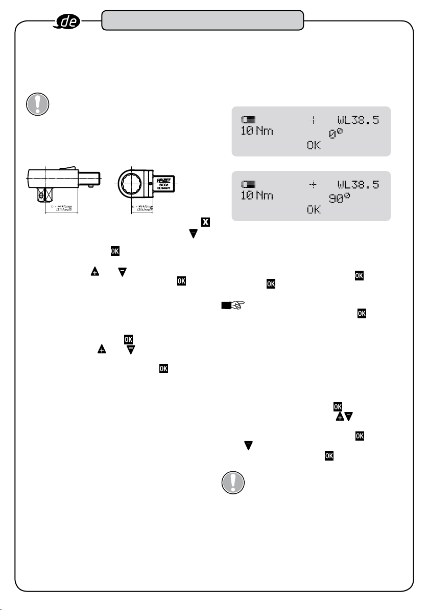
8.2 Drehwinkel
In dem Menüpunkt „Nm / °“ können Sie auch die
Programmierung für das Schrauben-Anzugsverfahren
mit „Drehwinkel“ vornehmen.
1. Nach Betätigung mit
können Sie den Wert für das Fügemoment mit
einstellen.
2. Nach Bestätigung des Wertes mit
den Wert für den Drehwinkel mit
Einstellung erfolgt in 5°-Schritten.
3. Nach Bestätigung dieses Wertes mit
des Fügemomentes und des Drehwinkelwertes defi
niert.
ACHTUNG! Der Modus „Drehwinkel“ ist nur aktiv,
wenn die Drehwinkeleinstellung auf einen Wert grö
ßer 0° eingestellt ist.
HINWEIS!
Drehwinkel-Schlüssels informieren den
Anwender, zusätzlich zu den Zahlenwerten auf
dem Display, über das jeweils aufgebrachte
Drehmoment bzw, den aufgebrachten
Drehwinkel.
Die Signale des Drehmoment-/
im Menüpunkt „Nm / °“
können Sie
einstellen. Die
ist die Eing abe
-
8.3 Anwendung / Betätigung des
Drehmoment-/Drehwinkel-Schlüssels:
Der Drehmoment-/Drehwinkel-Schlüssel sollte ausschließlich am Handgriff rechtwinklig zur Schraubverbindung
betätigt werden! Die eingesetzte Handkraft muss gleich
mäßig auf die Mitte des Handgriffs (Ringmarkierung)
aufgebracht werden.
Um Messfehler bei der Drehwinkelmessung zu vermeiden,
darf sich das zu verschraubende Werkstück oder dessen
Auflage während der Betätigung nicht mitdrehen, bewe
gen oder schwanken.
9. Justierung / Kalibrierung:
Ein elektronischer Drehmoment-/Drehwinkel-Schlüssel
sollte regelmäßig überprüft und kalibriert werden. Nach
längerem Gebrauch ist eine werkseitige Neu-Zertifizierung
bzw. Re-Kalibrierung ratsam. Elektronische Drehmoment-/
Drehwinkel-Schlüssel sind Messwerkzeuge.
Messwerkzeuge sind in den vom Qualitätsmanagement
festgelegten Zeitabständen mit dafür geeigneten
Messeinrichtungen zu prüfen und bei Bedarf zu justieren.
Der Zeitabstand zwischen den Prüfterminen ist abhängig
von der Häufigkeit der Nutzung. Wir empfehlen dies nach
ca. 5000 Schraubvorgängen, spätestens aber nach sechs
Monaten.
HINWEIS!
Informationen über den Softwarestand, die
Seriennummer, das Datum der letzten
Kalibrierung und die verbleibende Anzahl an
Auslösungen bis zur nächsten Kalibrierung des
Schlüssels.
Im Menüpunkt „PC“ stehen
1. Um die Informationen unter dem Menüpunkt „PC“
aufzurufen, müssen Sie mit
seln und vorzugsweise mit den Menüpunkt „PC“
auswählen.
2. Nach Betätigung von
Sie die Informationen zum Softwarestand einsehen.
HAZET verfügt über entsprechende Prüfeinrichtungen.
Die an HAZET eingesandten HAZET-Drehmoment-/
Drehwinkel-Schlüssel erhalten Sie nach Überprüfung
und eventuell notwendiger Justierung /Kalibrierung mit
Prüfzertifikaten zurück. Die bei HAZET eingesetzten
Drehmoment- und Drehwinkel-Prüfeinrichtungen wer
den durch den deutschen Kalibrierdienst (DKD) ständig
überwacht und wenn notwendig kalibriert bzw. justiert.
Dies sichert die vorhandene, notwendige Kompetenz
auf dem Gebiet des kontrollierten Schraubanzuges und
die Qualität des HAZET-Werkzeuges.
Wir nehmen den elektronischen Drehmoment-/
Drehwinkel-Schlüssel auch über Ihren Fachhändler zur
Überprüfung und Kalibrierung ins HAZET-WERK.
in das Menü wech-
im Menüpunkt „PC“ können
10. Drehmoment-/Drehwinkel-Zertifikate
und Kalibrieranweisung
Jedem Drehmoment-/Drehwinkel-Schlüssel liegt ein
Qualitäts-Prüfzertifikat nach DIN 55350-18-4.2.2 bei.
Bei Verlust der Zertifikate oder bei Bedarf der
Kalibrieranweisung wenden Sie sich bitte an das
HAZET-Service-Center.
-
11. Zubehör:
Zu allen HAZET-Drehmoment-/Drehwinkel-Schlüsseln
ist umfangreiches Qualitätszubehör lieferbar. Siehe im
HAZET-Werkzeug-Handbuch oder im Internet unter:
www.hazet.de oder www.hazet.com
12. Wartung und Pflege:
Alle innen liegenden mechanischen und elektronischen
Funktionselemente sind wartungsfrei.
-
11

Aufbau und Funktion
13. Störungen:
Meldung Ursache Maßnahme
Keine Anzeige im Display Keine Batterien eingelegt, Batterien
Keine Anzeige im Display Sind neue und volle Batterien richtig
„System n.i.O“ Beim Einschalten läuft ein elektro
„System n.i.O“ Wenn sicher gestellt ist, das der
„Service“ Erscheint nach dem Einschalten des
Bei Betätigung des Drehmoment-/
Drehwinkel-Schlüssels wird kein Wert
auf dem Display gezeigt.
Drehmoment- oder Drehwinkelwert
im Wechsel mit n.i.O.
falsch eingelegt oder Batterien sind
entladen
eingelegt und es erscheint nach dem
Einschalten, durch 2x gleichzeitiges
Betätigen von
keine Anzeige, ist der Drehmoment-/
Drehwinkel-Schlüssel defekt.
nischer Systemtest. Wurde der
Drehmoment-/Drehwinkel-Schlüssel
beim Einschalten belastet, erscheint
die Meldung
„System n.i.O“.
Drehmoment-/Drehwinkel-Schlüssel
beim Einschalten unbelastet war
und die Meldung „System n.i.O“
trotzdem erscheint, arbeiten die
Drehmomentsensoren, z.B. nach
einer Überlastung, nicht einwandfrei.
Drehmoment-/Drehwinkel-Schlüssels
die Anzeige „Service“ ist das ein
Hinweis darauf, dass nach der letzten
Kalibrierung 5000 Lastwechsel durch
geführt wurden.
Sie befinden sich im Start- Display.
Die „OK“- Anzeige wird angezeigt.
Der gezogene Drehmoment- oder
Drehwinkelwert war nicht in der
Toleranz des Zielwertes. Der
Drehmoment- oder Drehwinkelwert
war zu niedrig. Beim Betätigen wurde
keine oder nur die erste Signalstufe
aktiviert.
und trotzdem
Neue, volle Batterien richtig einlegen,
siehe Punkt 7 Inbetriebnahme
Schicken Sie den Drehmoment-/
Drehwinkel-Schlüssel zur Überprüfung
zu Ihrem HAZET- Service.
-
Schalten Sie den Drehmoment- /
Drehwinkel-Schlüssel durch gleichzeitiges Betätigen von und
aus. Legen Sie den Drehmoment-/
Drehwinkel-Schlüssel, unbelastet
auf eine gerade, stabile Unterlage.
Zum Einschalten des Drehmoment-/
Drehwinkel-Schlüssels betätigen Sie
erneut und gleichzeitig.
Schicken Sie den Drehmoment-/
Drehwinkel-Schlüssel zur Überprüfung
zu Ihrem HAZET-Service.
Wenn Sie diesen Hinweis ignorieren
möchten, betätigen Sie und
gleichzeitig. Es kann umgehend weiter gearbeitet werden. Diese Meldung
-
erscheint bei jedem Einschalten
erneut.
Schicken Sie den Drehmoment-/
Drehwinkel-Schlüssel zum Kalibrieren
zu Ihrem HAZET- Service.
Kontrollieren Sie die Einstellungen
sorgfältig. Bestätigen Sie die
Einstellungen durch Betätigen von
. Die Anzeige „OK“ erlischt. Der
Drehmoment-/Drehwinkel-Schlüssel
ist betriebsbereit.
Verfahren Sie entsprechend den
Anweisungen für diesen Schraubfall:
z.B. Schraube lösen und erneut anzie
hen oder durch eine neue Schraube
ersetzen.
Erhöhen Sie behutsam das
Drehmoment. Achten Sie auf die
Betätigungsgeschwindigkeit und
die Signalstufen. Betätigen Sie den
Drehmoment-/Drehwinkel-Schlüssel
so, dass Sie innerhalb der zweiten
Signalstufe bleiben.
-
12

Aufbau und Funktion
13. Störungen:
Meldung Ursache Maßnahme
Drehmoment- oder Drehwinkelwert
im Wechsel mit n.i.O.
Die vierte Signalstufe mit rotem
Dauerlicht, Dauer- Signalton und
Dauer- Vibration spricht an.
Es erscheint der Hinweis:
„Error“
Blinkendes Batteriesymbol Die Batterien oder Akkus sind ent
Die Drehwinkelmessung / -anzeige
steigt während der Betätigung nicht
weiter an bzw. fällt kurzzeitig aus.
Der Drehwinkel wird nicht gemessen
bzw. angezeigt
Der gezogene Drehmoment- oder
Drehwinkelwert war nicht in der
Toleranz des Zielwertes. Der
Drehmoment- oder Drehwinkelwert
war zu hoch. Beim Betätigen wurde
die dritte oder vierte Signalstufe akti
viert.
Das aufgebrachte Drehmoment
war oberhalb des maximal zuläs
sigen Drehmomentbereiches des
Drehmoment-/Drehwinkel-Schlüssels.
laden.
Das Fügemoment wurde am
Anfang des Gewindes bzw. der
Betätigung überschritten, wodurch
die Drehwinkelmessung aktiviert
wurde. Beim Weiterdrehen fällt das
Drehmoment unter das zuvor erreich
te Fügemoment. Das kann auftreten,
wenn das Gewinde beschädigt oder
verschmutzt ist.
Die Schraube ist schon so fest (vor-)
angezogen, dass sie sich nicht mehr
weiter dreht. Das kann auftreten,
wenn die Schraube z.B. mit einem
Schlagschrauber eingedreht wurde
Verfahren Sie entsprechend den
Anweisungen für diesen Schraubfall:
z.B. Schraube lösen und erneut anziehen oder durch eine neue Schraube
ersetzen.
-
Verringern Sie die Betätigungskraft.
Achten Sie auf die
Betätigungsgeschwindigkeit und
die Signalstufen. Betätigen Sie den
Drehmoment-/Drehwinkel-Schlüssel
so, dass Sie innerhalb der zweiten
Signalstufe bleiben.
Erreichen Sie die vierte Signalstufe,
-
müssen Sie den Schraubvorgang
sofort abbrechen. Bei Nichtbeachtung
können Sie den Drehmoment-/
Drehwinkel-Schlüssel beschädigen oder zerstören. Bestätigen Sie
den Heinweis durch gleichzeitiges
Betätigen von und . Schalten
Sie den Drehmoment-/DrehwinkelSchlüssel mit und aus und mit
und wieder ein
-
Betätigen Sie den Drehmoment-/
Drehwinkel-Schlüssel nicht mehr.
Wechseln Sie die Batterien oder
Akkus. Siehe Punkt 7 Inbetriebnahme
Verfahren Sie entsprechend den
Anweisungen für diesen
Schraubfall: z.B. Schraube lösen und
erneut anziehen oder durch eine neue
Schraube ersetzen. Ggf. Gewinde rei
-
nigen und / oder nachschneiden
Verfahren Sie entsprechend den
Anweisungen für diesen
Schraubfall: z.B. Schraube lösen und
erneut anziehen oder durch eine neue
Schraube ersetzen
-
14. Ersatzteile
• Lassen Sie alle Service- oder Reparaturarbeiten immer nur durch Fachpersonal ausführen. Wenden Sie sich dazu
bitte an den HAZET-Service.
• Es dürfen nur Original-HAZET-Ersatzteile verwendet werden.
• Falsche oder fehlerhafte Ersatzteile können zu Beschädigungen, Fehlfunktionen oder Totalausfall des Werkzeuges
führen.
• Bei Verwendung nicht freigegebener Ersatzteile erlöschen sämtliche Garantie-, Service-, Schadenersatz- und
Haftpflichtansprüche gegen den Hersteller oder seine Beauftragten, Händler und Vertreter.
• Tauschen Sie schwächer werdende Batterien oder Akkus gemeinsam und rechtzeitig aus. Verwenden Sie nur
Batterien und Akkus des gleichen Typs. Beachten Sie die Einbaurichtung.
13
Aufbau und Funktion
15. Reinigung / Lagerung /
Transport:
Das Werkzeug ist unter folgenden Bedingungen zu reinigen und zu lagern:
• Drehmoment-Drehwinkel-Schlüssel nur mit trocken
em Tuch reinigen.
• Keinen Flüssigkeiten und / oder aggressiven
Substanzen aussetzen.
• Drehmoment-Drehwinkel-Schlüssel nur in seiner
Verpackung lagern.
• Gegen Herunterfallen sichern.
• Trocken und staubfrei lagern.
• Nicht im Freien aufbewahren.
• Für Unbefugte unzugänglich aufbewahren.
• Lagertemperatur -10°C bis +40°C.
• Relative Luftfeuchtigkeit max. 60%.
ACHTUNG! Wenn Sie den DrehmomentDrehwinkel-Schlüssel längere Zeit nicht benut
zen, entnehmen Sie die Batterien oder Akkus.
Auslaufende Batterien und Akkus können
Beschädigungen am Werkzeug verursachen. Die
Batterien entladen sich auch, wenn der Drehmoment-/
Drehwinkel-Schlüssel nicht benutzt wird.
• Transportieren Sie den Drehmoment-/Drehwinkel-
Schlüssel nur in seiner Verpackung und sichern Sie ihn
beim Transport gegen Herunterfallen. Vermeiden Sie
schockartige, mechanische Einwirkungen, wie z.B.
harte Stöße oder Fallen lassen. Bei Nichtbeachtung
können die elektronischen Komponenten des
Drehmoment-/Drehwinkel-Schlüssels beschädigt
werden.
16. Entsorgung:
• Zur Entsorgung reinigen und zerlegen Sie den
Drehmoment-/Drehwinkel-Schlüssel unter Beachtung
geltender Arbeits- und Umweltschutzvorschriften.
• Führen Sie die Bestandteile der Wiederverwertung
zu. Entsorgen Sie elektronische Bauteile, Batterien
und Akkus entsprechend den gesetzlichen
Bestimmungen und Umweltschutzvorschriften z.B.
bei Altmaterialsammelstellen bzw. Wertstoffhöfen.
Verschrotten Sie metallische Materialreste.
• Elektroschrott, Elektronikkomponenten,
Schmier- und andere Hilfsstoffe unterliegen
der Sondermüllbehandlung und dürfen nur
von zugelassenen Fachbetrieben entsorgt werden!
• Die Verringerung von Umweltbelastungen und die
Bewahrung der Umwelt, stehen im Mittelpunkt
unserer Aktivitäten!
-
17. Hotline / Kontakt:
Dieses Produkt wurde nach unseren hohen
Qualitätsansprüchen entwickelt und geprüft. Sollten Sie
Fragen, Anmerkungen, Verbesserungsvorschläge oder
Änderungswünsche haben, sind wir Ihnen im Sinne aller
HAZET-Kunden dafür dankbar und stehen Ihnen gerne
zur Verfügung
Ihr Ansprechpartner für: Gewährleistung ·
Instandsetzung · Justierung · Kalibrierung ist der HAZETPartner vor Ort oder das HAZET Service-Center:
service-center@hazet.de
14

For Your Information
1
1. General Information
This torque wrench with built-in angle gauge
has been developed to enable the controlled
tightening and loosening of screw connec
tors with right- and left-handed threads.
Every HAZET torque wrench with built-in angle gauge
is calibrated for torque as per DIN EN ISO 6789 and for
angle gauges as per factory settings, and delivered with
a serial number, operating instructions and certification.
For intended use of the torque wrench with built-in angle
gauge, it is essential that all safety and other information
in these operating instructions is adhered to. This is the
only way to guarantee problem-free usage of this preci
sion tool in the long term.
Always keep these operating instructions together with
your HAZET tool.
WARNING: Observe all safety, warning and operating
instructions to ensure the safe and trouble-free opera
tion of the tool, and to avoid immediate hazards. Please
pay attention to the following symbols.
2. Explanation of Symbols
READ THE OPERATING INSTRUCTIONS!
-
NOTE!
CAUTION!
-
ATTENTION!
-
QUALIFIED PERSONNEL ONLY!.
The operator is obliged to observe the operating instructions and to instruct all users of the
tool in accordance with the operating instruc
tions.
This symbol marks advice which is helpful
when using the device.
This symbol indicates important specifications, dangerous conditions, safety risks and
safety advice.
This symbol indicates advice which if disregarded results in damage, malfunction and/or
functional failure of the device.
Tool may be used by qualified personnel only.
Disregard may lead to injuries to persons or
damage to the tool or the workpiece
-
15

For Your Safety
2
1. General Aspects
CAUTION! Specialist technical knowledge and/
or suitable training is required for the use and
repair of this tool.
This device was developed and manufactured accord
ing to the technical norms and standards valid at the
time and is considered to be operationally reliable.
Nevertheless, the tool set can present a danger when
it is not used as intended or in an inappropriate way by
non-qualified personnel. All persons using or maintain
ing this tool must carefully read and understand these
operating instructions before commencing work.
2. Owner’s Liability
• Keep the operating instructions together with the tool
at all times. If the operating instructions have been
mislaid or made unusable, please contact your spe
cialist dealer or the HAZET Service Centre.
• Before each use, check the torque wrench with builtin angle gauge for full functionality. Do not use the
tool if its functional efficiency cannot be ensured or if
damage is detected. If the tool is used when it is not
in full working order, there is a risk of severe personal
injury and property damage.
• The torque wrench with built-in angle gauge must
only be used if it is in good working condition. If the
device does not work properly, it must be removed
from service and inspected.
• All safety warning and operating instructions on the
device must be observed, and always be in an easilylegible condition. Damaged descriptions, labels or
stickers as well as the display cover must be imme
diately replaced.
• In addition to the occupational safety advice given
in these operating instructions, the general safety
regulations, regulations for the prevention of acci
dents and regulations for environmental protection
applicable for the use of this tool must be observed
and respected.
• All safety equipment must always be within reach and
should be checked regularly.
• Familiarise yourself with the operation of the torque
wrench with built-in angle gauge and undergo train
ing for working with the tool before starting work.
Before use, carefully check that all programmed set
tings are correct. The quality of your screwing work
will be dependent on these settings.
3. Intended use
• Operational reliability can only be ensured if the tool
is used as intended and in compliance with the indi
cations given in the operating instructions. Any deviation from the intended use and/or any misapplication
of the device is prohibited and will be considered as
improper use.
• Ensure that tools are always used, inspected and main
tained in compliance with the respective local, state,
national or federal regulations.
-
• HA ZE T torque wrenches with built-in angle gauge are
solely designed to enable the controlled tightening
and loosening of screw connectors.
• The wrench should under no circumstances be used
as a lever tool, clamping tool or impact tool. Improper
use, use which is not compliant with the safety
instructions or overloading of the HAZET torque/
rotation angle wrench can lead to incorrect measure
ments and/or to a failure of the system, and thus to
death, severe damage to your body or health, as well
as to property.
• Torque wrenches with built-in angle gauge are cali
brated measurement tools and as such must be
treated with care. For this reason mechanical, chemi
cal or thermal impacts which go beyond the capabilities of its intended use should be avoided. The
torque wrench with built-in angle gauge must not be
exposed to rain or humidity, or immersed in a liquid.
Do not allow foreign bodies to enter, and always
cover the sockets when not in use. Extreme climatic
conditions such as cold, heat, humidity can affect
the measurement values or affect the measurement
results. Non-compliance can damage or destroy the
torque wrench with built-in angle gauge.
-
• Incorrect use of the contained tool or use whilst fail
ing to comply with the safety instructions can result
in serious injury.
• Any deviation from the intended use and/or any
misapplication of the tool is prohibited and will be
considered as improper use.
• Before use, check that the insert used and/or the
plug tool are/is seated firmly. Position the tool so
that it cannot slip out from the screw connection.
Otherwise, there is a risk of personal injury and/or
property damage.
-
• When using inserts or plug tools, it is vital to ensure
their design conforms to standards and that their
shape and size are correct for the screw joint to be
tightened.
• Also adhere to the maximum permitted load for the
insert or plug tool used. These may be lower than
the possible release torque of the torque wrench with
built-in angle gauge. The use of home-made special
ised tools can be a source of danger. Failure to comply
can result in personal injury and/or material damage.
-
-
-
-
-
-
-
16

For Your Safety
2
• Any claims against the manufacturer and/or its
authorised agents because of damage caused by
improper use of the tool are invalid.
• Any personal injury or material losses caused by
improper use of the tool are the sole responsibility
of the owner..
4. Dangers that may arise
from the tool
• Never modify the tool. For safety reasons, any
modifications, additions or conversions to the torque
wrench with built-in angle gauge are strictly forbid
den. Safety devices and/or housing parts may not be
removed. Never operate the tool if a protective cover
is missing or if not all of the safety devices / guards
are fitted and in perfect condition.
• The maximum permitted torque may not be exceed
ed in either direction of operation. All limit values,
setting values and setting ranges given must com
pulsorily be observed.
• Take care to maintain a safe, balanced position when
working.
• Only use the tools in locations prescribed and gov
erned under the current regulations relating to the
working environment.
CAUTION!
Do not use in explosive atmospheres
-
-
-
-
• Any claims against the manufacturer and/or its
authorized agents because of damage caused by
improper use of the device are void. Any modification
to the device and/or improper use will result in imme
diate exclusion from warranty and liability. Any personal injury or material losses caused by improper
use of the tool are the sole responsibilit y of the owner.
-
17

Design and Function
3
1. Technical Data / Device Elements
Technical Description
HAZET No. 7292-eTAC
Torque indicating range (Nm): 5 – 200
Torque measuring range (Nm): 10 – 200
Torque unit Nm
Relative measurement uncertainty for torque measuring range ± 2 % / ± 1 Digit
Torque tolerance range ± 8 %
Measurement range for rotation angle (cumulative) 5° bis 995°
Relative measurement uncertainty for rotation angle measuring range ± 2 % / ± 1°
Rotation angle tolerance range
Insert square (mm) 14 x 18
Adjusted with insert tool
Effective length (Wl) / gauge lw (mm)
Length with / without insert tool (mm) 580 / 518
Weight with / without insert tool (kg) 1.25 / 0.98
Menu languages Icons
Protection class IP 40
Batteries
4 x 1.2 Volt AA rechargeable batteries
Version
5° - 15° = ± 1°
20° - 25° = ± 2°
30° - 35° = ± 3°
from 90° = ± 10°
6404-1 3
38.5
4 x 1.5 Volt AA or
2. Included in Delivery
• Torque wrench with built-in angle gauge with operating instructions, test certificate, batteries, insertreversible ratchets per the table above, in protective
packaging.
18

Design and Function
3
3. Function/Signal Levels
• The torque wrench with built-in angle gauge has four
signal levels combining visual, audible and tactile
signals, which correspond to the attainment of set
values.
• The visible signals appear below the matted ring on
the handle, the audible signals are generated by a
buzzer in the housing and the tactile signals are cre
ated by a vibration motor in the handle.
• The torque wrench with built-in angle gauge has two
operating modes: “Torque” and “Angle gauge” (Nm/°).
• A single flashing yellow light indicates the point when
joint torque is reached, and angle measurement
starts.
• The first signal level, with its yellow flashing light,
audible signal and low-frequency vibration starts
when the applied torque and/or the applied rotation
angle reaches 80% of the target value range. When
the first signal level is reached, you should reduce the
approach speed and pay increased attention to the
force that you are using, as well as the display and
the signals of the torque wrench with built-in angle
gauge. The lower the target value, the faster you will
reach the first signal level.
• The second signal level, with its green flashing lights,
audible signal and medium-frequency vibration, indi
cates that the applied torque and/or the applied
rotation angle is within the target value range. If the
second signal level is reached, the screwing process
must be stopped in this range. The lower the target
value, the faster you will reach the second signal
level.
• The third signal level, with its red flashing light, audible
signal and high-frequency vibration, indicates that
the applied torque and/or the applied rotation angle
exceed the target value range. If the third signal level
is reached, the applied torque and/or the applied
rotation angle is too high. Stop the screwing process.
Proceed according to the instructions for such screw
ing incidents: for example, loosen the screw and
tighten it again, or replace it with a new screw.
• The fourth signal level, with its continuous red light,
continuous audible signal and continuous vibration,
indicates that the applied torque exceeds the maxi
mum permissible torque range of the torque wrench
with built-in angle gauge. If you reach the fourth signal
level, you must interrupt the screwing process imme
diately. Non-compliance can damage or destroy the
torque wrench with built-in angle gauge.
• If no further torque or rotation angle is applied after
operation, the maximum value for this process will be
displayed on the display alternating with a O.K. - or
N.O.K. - message.
• The torque wrench with built-in angle gauge can be
programmed to operate in a right-handed (+) or lefthanded (-) direction of rotation.
NOTE!
In “torque wrench” mode, the screwing
process is switched off after 2 seconds, pro
vided that no torque is applied during this time.
In “ rotation angle” mode, the screwing process
is switched off after 4 seconds, provided that no
rotation angle is applied during this time.
NOTE!
When the screwing process is stopped,
-
the relevant final value (torque /rotation angle) is
displayed alternating with the O.K. or N.O.K.
message.
The next screwing process can only performed
after confirming the screwing process using
• The orientation of the display can be rotated for easy
reading by pressing a button, regardless of the direc
tion of operation or handling.
• When the torque wrench with built-in angle gauge
is not in use, the wrench will switch itself off after
5 minutes.
Signals Table:
Signal levels Torque
Level 1 (threshold value)
Yellow flashing light
audible signal and
-
low-frequency vibration
Level 2 (within target
value range)
green flashing light,
audible signal and
medium-frequency vibration
Level 3 (above target
value range)
red flashing light,
audible signal and
high-frequency vibration
Level 4 (above maximum
-
-
-
torque)
continuous red light
continuous audible signal and
continuous vibration
Single flashing yellow
light
when joint torque is
reached =
Start of angle measurement
v v
v v
v v
v v
Rotation
-
.
-
angle
v
19

Design and Function
3
4. Display / Panel / Quick start guide
Buttons / Quick start guide
Switching on
Switching off
Confirmation
Open/close menu
Move up in the menu /
Adjust numerical values upwards
Move down in the menu /
Adjust numerical values downwards
Confirm instructions
Rotate the display
5.1 Menu Structure
Level 1
- Switch with
1.
- Switch with
+ / –
2.
- Switch with
+ / –
3.
- Switch with
+ / –
4.
- Switch with
+ / –
Nm / ° Torque Rotation angle
WL Effective Length
+/–
PC
Battery display
eTAC
Made in Germany
- arrow
Direction of rotation
+ arrow
Torque target value
and/or snug torque
Press
and twice briefly at the same time and release
Press
and twice briefly at the same time and release
Press
and at the same time
and at the same time
Press
Level 2
- Switch with
Right (+)
Left (–)
Displays the software version
Number of releases
Effective length
x
OK
Rotation angle
Level 3
- Switch with
PC connection
( can only be used at the factory)
• • •
20

Design and Function
3
6. Before commissioning
Ensure that tools are always used, inspected and maintained in compliance with the
respective local, state, national or federal
regulations.
To prevent failures in the transfer of force, do not use
hinged joints or extensions if at all possible. The torque
applied to the screw joint can change dramatically when
using hinged joints.
Ensure that the insert tool, the wrench inserts or other
accessories in use are firmly seated. When using a
reversible ratchet, check the desired direction of rota
tion setting. The lever at the top of the insert-reversible
ratchet switches the ratchet between right-hand and
left-hand operation.
When using inserts, it is vital to ensure their design
conforms to standards and that their shape and size
are correct for the screw joint to be tightened. You must
also comply with the maximum permitted load for the
insert used. This may be lower than the possible torque
of the torque wrench with built-in angle gauge. The use
of modified tools or home-made specialised tools are a
source of danger. Do not use worn or damaged tools or
inserts. Failure to comply can result in personal injury
and/or material damage.
Position the tool so that it cannot slip out from the screw
connection. Take care to maintain a safe, balanced posi
tion when working. Otherwise, there is a risk of personal
injury and/or property damage.
It is possible for screw joints to become loose. You
should therefore never exceed the maximum torque of
the torque wrench with built-in angle gauge (e.g. when
loosening rusted screws). Overloading can damage the
torque wrench with built-in angle gauge and distort the
release value.
When working with rotation angles, ensure that the
expected torque at the set rotation angle does not
exceed the maximum permissible torque of the tool.
7. Commissioning
7.1 Inserting or replacing batteries:
1. Open the screw cap on the end of the grip.
2. Remove the plastic sleeve, with the discharged batter
ies, from the main tube.
3. Refill the plastic sleeve with the required batteries or
rechargeable cells.
NOTE!
The battery symbol on the display indicates
the charging status of the inserted batteries or
-
-
rechargeable cells. When the batteries/rechargeable
cells are discharged, a flashing battery symbol will
appear. No further work will be possible, and the
batteries/cells must be replaced. Discharged batter
ies/rechargeable cells can be pushed out of the
sleeve using the new batteries/cells.
ATTENTION! Ensure that the new batteries are all
inserted into the sleeve in the same direction. Only
replace the batteries or cells as a set. Only use bat
teries or cells of the same type.
The batteries are included in the delivery are not
rechargeable!
4. Insert the sleeve together with the batteries, with the
positive pole facing outwards, into the main tube.
5. Close and tighten the screw cap at the end of the
handle manually.
7.2 Settings
7.2.1 Switching on and off
Ensure that the torque wrench with built-in angle gauge
is not under load when switching on.
Press
release – the wrench is switched on.
Press
release – the wrench is switched off.
When switching on for the first time, the display will
show the factory settings and the battery charge status
display.
7.2.2 Menu access
Normally, you can access the menu using
you can then access the individual menu items using
or configure settings, depending on the menu option.
These must be confirmed using
times if necessary, allows you to exit the menu and/or
the menu options.
and twice briefly at the same time and
and once briefly at the same time and
NOTE!
Should the message “System N.O.K.”
or “Service” appear, please refer to the chapter
“Malfunctions“ on pages 24/25.
NOTE!
The orientation of the display can be
rotated for easy reading by pressing
the same time, regardless of the direction of
operation or handling.
. You can then either select menu sub-options
. Pressing , several
-
-
-
at
. Here,
21

Design and Function
3
7.3 Effective Lengths
You must enter the gauge lw of the plug
tool that you are using in the “WL” menu option.
For the gauges of HAZET plug tools, please refer to the
relevant tool manual.
ATTENTION! If the programmed effective
length does not match the effective length of
the plug tool used, there will be a discrepancy
between the torque value shown on the display
and that applied to the screw joint.
1. In order to set the effective length, you will need to
switch to the menu using
“WL” menu option using
2. After pressing
set the effective lengths of the used plug tools using
or .
3. Confirm the value you have input using
in the “WL” menu option, you can
and preferably select the
.
.
7.4 Direction of rotation
You will need to use the “+ / -” menu option to set the
direction of rotation in which you want to operate the
wrench by choosing right (+) or left (-).
1. After pressing
can set the direction of rotation using
2. Confirm this setting by pressing
in the “+ / -” menu option, you
or .
.
8. Programming
The last programmed settings are displayed when the
wrench is switched on. The individual modes are dis
played as follows:
• Torque mode,
• Rotation angle mode,
Check that the display shows the mode in which you
want to work.
Carefully check that all programmed setting values are
correct. Once all settings for the next screwing process
which you want to perform are correct, confirm the
entries using the
the torque wrench is ready to use.
Note!
changes by pressing , the torque wrench
with built-in angle gauge is not ready for use.
No display will appear when you switch it on.
button. The symbol appears and
If you do not confirm your settings/
8.1 Torque:
The “Nm / °” menu option enables you to perform the
programming for the screw tightening process using
“Torque”.
1. By selecting the “Nm / °” menu option, after confirm
ing using , you can set the “Target value” value
for torque using
steps.
2. After confirming the value using
set the value for the rotation angle to 0°using
3. After confirming using
torque target value.
ATTENTION! “Torque” mode is only active when
the rotation angle is set to 0°.
. The setting changes in 1 Nm
, you will need to
.
, you will have defined the
-
-
22

Design and Function
3
8.2 Rotation angle
The “Nm / °” menu option also enables you to perform
the programming for the screw tightening process using
“Rotation angle”.
1. After selecting
set the joint torque value using
2. After confirming the value using
value for the rotation angle using
changes in 5° steps.
3. After confirming this value using
defined the joint torque and the rotation angle values.
ATTENTION! “Rotation angle” mode is only active
when the rotation angle is set to a value greater
than 0°.
NOTE!
built-in angle gauge give the user not only the
numeric values on the display, but also the
applied torque wrench as well as the applied
rotation angle.
in the “Nm / °” menu option, you can
.
, you can set the
. The setting
, you will have
The signals of the torque wrench with
8.3 Use / operating the torque wrench
with built-in angle gauge:
The torque wrench with built-in angle gauge should only
be operated with the handle at right angles to the screw
joint. The hand force deployed must be applied uniformly
onto the centre of the handle (ring marking).
In order to avoid measurement errors when measuring the
rotation angle, the work piece to be screwed or its support
should not rotate, move or shake during the operation.
wrenches with built-in angle gauge and torque testers sent to HAZET are supplied with a test certificate.
The HAZET torque and rotation angle testing devices
are constantly supervised by the German Calibration
Service (DKD), and calibrated and/or adjusted as
required. This guarantees the level of expertise neces
sary for the field of controlled screw joint tightening and the quality of your HAZET tool.
We can also retrieve the electronic torque wrench with
built-in angle gauge via your specialist retailer for check
ing and calibration at the HAZET plant.
10. Torque and Rotation Angle Certificate
and Calibration Document
Every torque wrench with built-in angle gauge is provided with a quality test certificate in accordance with
DIN 55350-18-4.2.2.
Should you lose the certificate or if you are required to
do so in the calibration documents, please get in touch
with the HAZET Service Centre.
11. Accessories:
A l l HA ZE T to r qu e w r e nc he s wi t h b u ilt- i n a n g le g aug e s c a n
be p rovided w ith a wi d e ra nge o f qu a lity a cces s o r ies. F i n d
out more in your HAZET tool manual or on the Internet at:
www.hazet.de or www.hazet.com
12. Maintenance and care:
None of the internal mechanical and electronic functional elements require any maintenance.
-
-
9. Adjustment / calibration:
An electronic torque wrench with built-in angle gauge
should be checked and calibrated regularly. After a long
period of use, re-certification or re-calibration by the
factory is advisable. Electronic torque wrenches with
built-in angle gauges are measurement tools. Appropriate
measurement equipment must be used to test (and where
applicable, adjust) measurement tools at the time intervals
laid down by Quality Management.
The interval between test dates is dependent on the
frequency of use. We recommend testing after ca. 5000
screw operations, but no later than 6 months.
NOTE!
The “PC” menu option provides information on the software version, the serial number, the date of the last calibration, and the
remaining number of operations until the next
calibration of the wrench.
1. In order to call up information under the “PC” menu
item, you will need to switch to the menu using
and preferably select the “PC” menu option using
2. After confirming using
you will then be able to see information on the soft
ware version.
HAZET has the corresponding torque testers. After
testing and any adjustments required, HAZET torque
in the “PC” menu option,
.
-
23

Design and Function
3
13. Malfunctions:
Message Cause Action
Nothing shown on display No batteries inserted, batteries are
Nothing shown on display If new, charged batteries are correctly
"System N.O.K." An electronic system test runs when
"System N.O.K." If you have checked that the torque
"Service" If the message "Service" appears
No value is shown on the display
when the torque wrench with built-in
angle gauge is in use.
Torque or rotation angle value alter
nating with N.O.K.
wrongly inserted, or batteries are dis
charged
inserted and nothing appears on the
display after switching on by press
ing and twice simultaneously,
the torque wrench with built-in angle
gauge is defective.
the unit is switched on. If the torque
wrench with built-in angle gauge is
under load when it is switched on, the
following message will appear
"System N.O.K."
wrench with built-in angle gauge was
not subject to any load when it was
switched on and the "System N.O/K/"
still appears, the torque sensors are
not operating correctly, for example
after an overload.
when the torque wrench with builtin angle gauge is switched on, this
indicates that 5000 load operations
have been performed since the last
calibration.
You are on the start display. "OK" is
displayed.
-
The applied torque or rotation angle
value was not within the target value
tolerance. The torque or rotation angle
value was too low. No, or only the
first, signal level was activated during
operation.
Insert new, charged batteries
-
in the correct manner, see Item 7
Commissioning
Send the torque wrench with built-in
angle gauge for inspection at your
-
HAZET Service Centre.
Switch off the torque wrench with
built-in angle gauge by pressing
and simultaneously. Place the
torque wrench with built-in angle
gauge with no load on a smooth stable surface. To switch on the torque
wrench with built-in angle gauge,
press and simultaneously
again.
Send the torque wrench with built-in
angle gauge for inspection at your
HAZET Service Centre.
If you want to ignore this message,
confirmed by pressing
simultaneously. Work can continue
immediately. This message will continue to be displayed every time the
device is switched on.
Send the torque wrench with built-in
angle gauge for calibration at your
HAZET Service Centre.
Check the settings carefully. Confirm
the settings by pressing
is no longer displayed. The torque
wrench with built-in angle gauge is
ready for use.
Proceed according to the instructions
for such screwing incidents: for example, loosen the screw and tighten it
again, or replace it with a new screw.
Carefully increase the torque. Pay
attention to the actuation speed and
the signal levels. Operate the torque
wrench with built-in angle gauge in
such a way that you remain within the
second signal level.
and
. "OK"
24

Design and Function
3
13. Malfunctions:
Message Cause Action
The applied torque or rotation angle
Torque or rotation angle value alter
nating with N.O.K.
The fourth signal level with continuous
red light, continuous audible signal
and continuous vibration is triggered.
The following message appears:
"Error"
Flashing battery symbol The batteries or rechargeable cells are
The rotation angle measurement/dis
play does not continue to increase
during operation and/or drops briefly.
The rotation angle was not measured
and/or displayed
value was not within the target value
tolerance. The torque or actuation
angle value was too high. The third
or fourth signal levels were activated
during operation.
The applied torque exceeded the
maximum permissible torque range
of the torque wrench with built-in
angle gauge.
discharged.
-
The joint torque was exceeded at the
start of the thread and/or operation,
which activated the joint angle measurement. Further rotation will bring the
torque below the previously reached
joint torque. This can happen if the
thread is damaged or soiled.
The screw is now so firmly inserted
that it will no longer rotate. This can
happen if the screw has been inserted
for example with an impact screw
driver
Proceed according to the instructions
for such screwing incidents: for example, loosen the screw and tighten it
again, or replace it with a new screw.
Reduce the actuating force. Pay
attention to the actuation speed and
the signal levels. Operate the torque
wrench with built-in angle gauge in
such a way that you remain within the
second signal level.
If you reach the fourth signal level, you
must interrupt the screwing process
immediately. Non-compliance can
damage or destroy the torque wrench
with built-in angle gauge. Confirm the
message by simultaneously press
ing and . Switch off the torque
wrench with built-in angle gauge
using and and switch it back
on using and
Do not use the torque wrench with
built-in angle gauge any further.
Replace the batteries or rechargeable
cells. See Item 7 Commissioning
Proceed according to the instructions
for such
screwing incidents: for example, loos
en the screw and tighten it again, or
replace it with a new screw. If necessary, clean and/or re-cut the thread
Proceed according to the instructions
for such
screwing incidents: for example, loos
-
en the screw and tighten it again, or
replace it with a new screw
-
-
-
14. Spare Parts
• Allow all service or repair work to be carried out by qualified personnel only. To do this, please get in touch with
the HAZET Service team.
• Only the original HAZET spare parts should be used.
• Unsuitable or defective spare parts may cause damage to, or malfunction or total failure of the tool.
• The use of non-approved spare parts will void all warranty, service and liability claims as well as all claims for
compensation against the manufacturer or its agents, distributors and sales representatives.
• Batteries (rechargeable or otherwise) which are discharging must be replaced simultaneously as required, in a
timely fashion. Only use batteries or cells of the same type. Note the direction of insertion.
25

Design and Function
3
15. Cleaning / Storage / Transport
The tool must be cleaned and stored according to the
following conditions:
• Only clean the torque wrench with built-in angle
gauge with a dry cloth.
• Do not expose the tool to liquids and/or aggressive
substances.
• Only store the torque wrench with built-in angle
gauge in its packaging.
• Protect against falling.
• Keep in a dry and dust-free place.
• Do not store outdoors.
• Protect from unauthorised access.
• Storage temperature: -10 up to +40°C.
• Relative air humidity: max. 60%.
ATTENTION! Remove the batteries or cells if
the torque/angle wrench is not being used for
long periods of time. Battery leakage can dam
age the tool. The batteries will still discharge if the torque
wrench with built-in angle gauge is not used.
• Only transport the torque wrench with built-in angle
gauge in its packaging, and protect it from falls during
transportation. Avoid shock-like mechanical effects,
such as heavy blows or falls. Non-compliance can
cause damage to the electronic components of the
torque wrench with built-in angle gauge.
16. Disposal
• For disposal, clean the tool and disassemble the
torque wrench with built-in angle gauge according
to the regulations for work safety and environmental
protection.
• Recycle the components. Dispose of electronic
components, batteries and rechargeable cells in
accordance with legal regulations and environmental
directives, e.g. at scrap material collection points or
recycling centres. Scrap any residual metal.
• Electronic waste, electronic components,
lubrication and other auxiliary materials
must be treated as hazardous waste and
may only be disposed of by authorised specialists!
• Reducing environmental pollution and preserving
the environment are at the heart of our activities!
-
17. Hotline/Contact:
This product has been developed and tested in accordance with our high quality standards. We would be very
grateful on behalf of all HAZET customers should you
want to share any questions, comments, suggestions for
improvement or alterations, and we will be happy to help
Your contact for: Maintenance · Repair · Adjustments ·
Calibration is your local HAZET partner
26

Notizen / Notes
27

28
HAZET-WERK – Hermann Zerver GmbH & Co. KG • } 10 04 61 • D-42804 Remscheid • Germany
[ +49 (0) 21 91 / 7 92-0 • \ +49 (0) 21 91 / 7 92-375 (Deutschland) -400 (International)
^ hazet.de • ] info@hazet.de
223717 II.04.2014/0.2 be/MC
 Loading...