

Page 1
ISSQUARELV REV B
_______________________________________________________________________________________________________________________________________
OWNER’S MANUAL
INSTALLATION, OPERATION, & PARTS
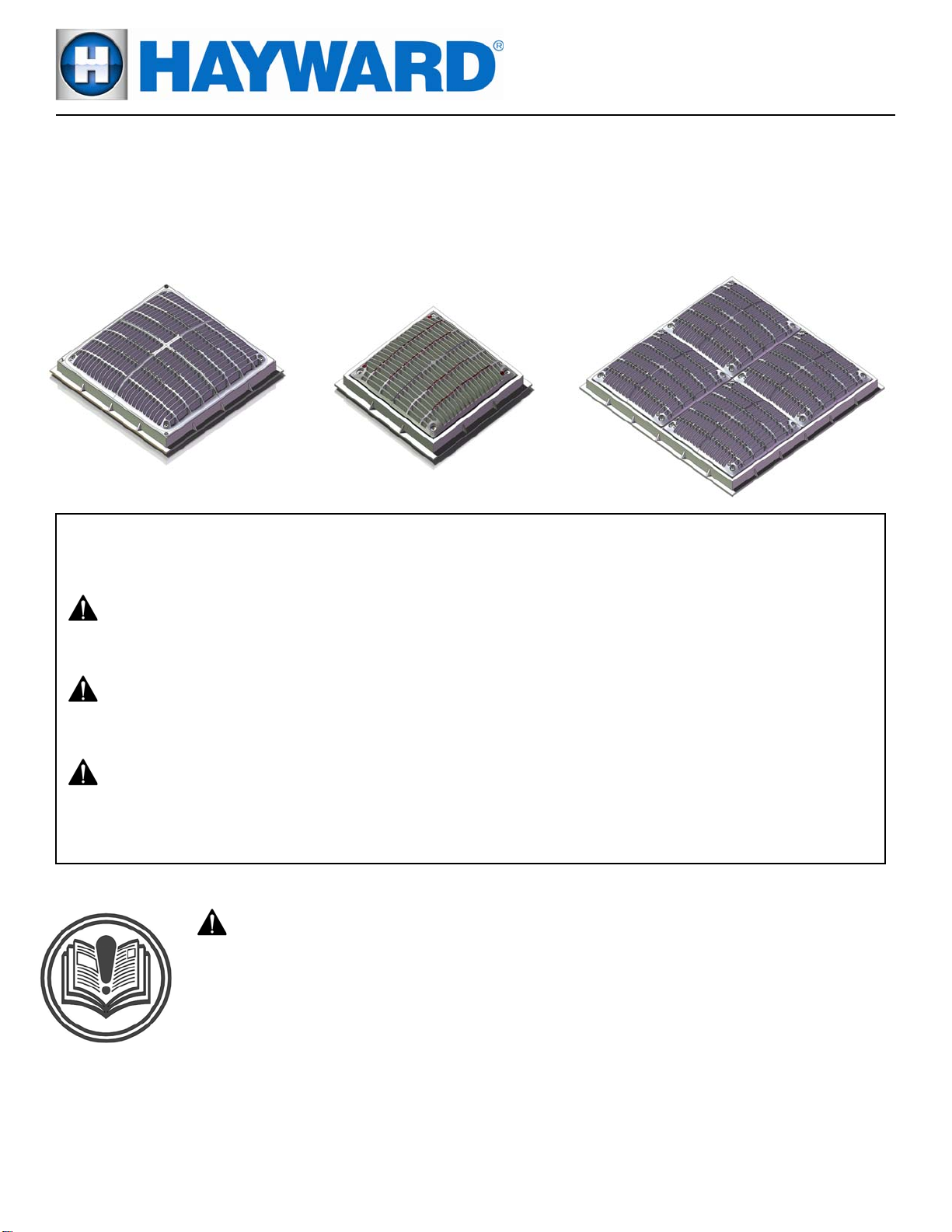
DUAL SUBMERGED SUCTION OUTLET SET
[Commonly called main drains]
Basic safety precautions should always be followed, including the following: Failure to follow
instructions can cause severe injury and/or death.
This is the safety-alert symbol. When you see this symbol on your equipment or in this manual,
look for one of the following signal words and be alert to the potential for personal injury.
WARNING warns about hazards that could cause serious personal injury, death or major
property damage and if ignored presents a potential hazard.
CAUTION warns about hazards that will or can cause minor or moderate personal injury
and/or property damage and if ignored presents a potential hazard. It can also make consumers
aware of actions that are unpredictable and unsafe.
- WARNING - Read and follow all instructions in this
owner’s manual and on the equipment. Failure to follow
instructions can cause severe injury and/or death.
IMPORTANT SAFETY INSTRUCTIONS
One Hayward Industrial Drive, Clemmons, NC 27012
Hayward Pool Products
Phone: 336-712-9900
www.haywardnet.com
Page 2
WARNING – Suction Entrapment Hazard.
Suction in suction outlets and/or suction outlet covers which are damaged, broken, cracked, missing, or
unsecured can cause severe injury or death due to the following entrapment hazards:
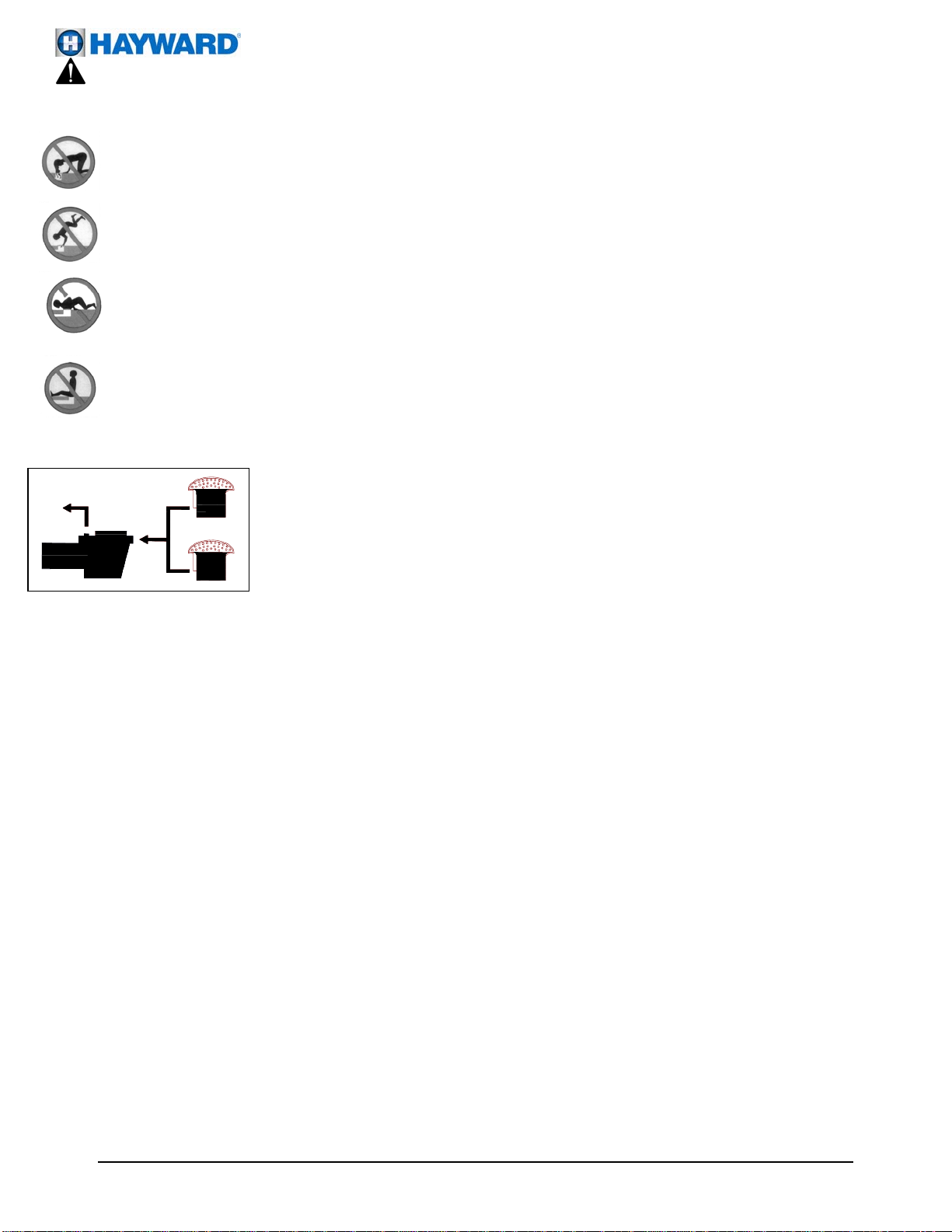
Hair Entrapment- Hair becomes knotted or snagged in an outlet cover.
Limb Entrapment- A limb sucked or inserted into an opening of a circulation outlet with a broken or missing cover
in the pool resulting in a mechanical bind or swelling
Body Suction Entrapment- Suction applied to a large portion of the body or limbs resulting in an entrapment.
Evisceration/ Disembowelment Entrapment- Suction applied directly to the intestines through an unprotected
sump or suction outlet with a missing or broken cover.
Mechanical Entrapment- Potential for jewelry, swimsuit, hair decorations, finger, toe or knuckle to be caught in
an opening of an outlet or cover.
To Reduce the risk of Entrapment Hazards:
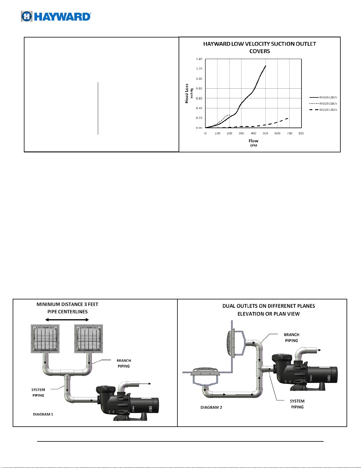
o A minimum of two functioning suction outlets per pump must be installed. Suction
outlets in the same plane (i.e. floor or wall), must be installed a minimum of three feet (3’)
[.91 meter] apart, as measured from suction pipe center to suction pipe center. (See
Diagram 1. If suction outlets are to be located closer then three feet (3’) [.91 meter] apart,
they shall be located in different planes (i.e., one on the bottom, and one on the vertical
wall, or one on each of two separate vertical walls.) (See Diagram 2)
o Dual suction fittings shall be placed in such locations and distances to avoid “dual blockage” by a user.
o Dual suction fittings shall not be located on seating areas or on the backrest for such seating areas.
o The maximum system flow rate shall not exceed the flow rating of any listed (per ASME/ANSI A112.19.8M-1987,
ASME A112.19.8-2007, APSP-7) suction outlet cover installed.
o Keep suction outlet components clear of debris, such as leaves, dirt, hair, paper and other material.
o Never use a Pool or Spa if any suction outlet component is damaged, broken, cracked, missing, or not securely
attached.
o Prior to each use of the swimming pool and/or spa, observe and replace damaged, broken, cracked, missing, or
not securely attached suction outlet components immediately.
o Remove pressure test plugs and/or plugs used in winterization of the pool/spa from the suction outlets.
o Two or more suction outlets per pump should be installed in accordance with latest APSP Standards and CPSC
guidelines. Follow all National, State, and Local codes applicable.
o Multiple layers of protection are available including installation of a vent pipe system, a gravity flow system, or a
vacuum release system.
o Suction outlet components have a finite life, the cover/grate should be inspected frequently and replaced at least
every seven years or if found to be damaged, broken, cracked, missing, or not securely attached.
o Do not exceed maximum flow rate stated on suction fitting.
o Only replace a pump with one with a similar flow curve, avoid a pump with a higher horsepower rating.
o To reduce the risk of body entrapment, installation of the field fabricated sumps must be such that the top of the
mounted WG1031BHF cover is a minimum of 1 ½” above; and the top of the mounted WG1032BHF cover is a
minimum of 1 13/16” above, the finished pool surface over an area larger than 40” on a diagonal.
USE ONLY HAYWARD GENUINE REPLACEMENT PARTS
Page 2 of 8
DUAL SUCTION OUTLET SET ISSQUARELV REV B
Page 3
RECOMMENDED SYSTEM SPECIFICATIONS:
ACCEPTABLE PIPE SIZE FOR MAXIMUM
RECOMMENDED
SYSTEM FLOW RATE PER APSP-7
(6 FT/SEC IN THE BRANCH LINE)
Pipe Size
[mm]
2 ½”
[75]
3”
[90]
WG1031BLV Suction Outlet Cover (Replacement sold as a WGX1031BLV) is rated for 108 GPM Wall Mounted or 190 GPM Floor Mounted for
single or multiple suction outlet use. (9” x 9”)
WG1032BLV Suction Outlet Cover (Replacement sold as a WGX1032BLV) is rated for 260 GPM Wall Mounted or 392 GPM Floor Mounted for
single or multiple suction outlet use. (12” x 12”)
WG1033BLV Suction Outlet Cover (Replacement sold as a WGX1033BLV) is rated for 520 GPM Wall Mounted or 520 GPM Floor Mounted for
single or multiple suction outlet use (This is a package of four 9” x 9” covers and frames) (18” x 18”)
In the event of one suction outlet being blocked, the remaining suction outlets serving that system shall have a flow rating capable of the
full flow of the pump(s) for the specific suction system.
Example: In the System shown in Diagram 1, two (2) 12” x 12” suction outlet covers are selected and mounted on the floor. These covers
are individually rated for 392 GPM. For a desired flow rate through the pump of 120 GPM, a minimum pipe size from the Chart 1 is
selected at 3”. At the desired flow of 120 GPM one cover could be partially blocked and the other suction outlet flow would be below
the rated 392 GPM of the “Floor” mounted suction outlet cover. Since there are two outlets flowing in normal operation, and the
allowable velocity in the interconnecting piping is only 3ft/sec, the same pipe size is required in the interconnecting piping.
Example: In the System shown in Diagram 2, one (1) 12” x 12” suction outlet cover mounted in the floor, rated at 392 GPM, and one (1)
12” x 12” suction outlet cover mounted on the wall, rated at 260 GPM. For a desired flow rate through the pump of 200 GPM, a
minimum pipe size from the Chart 1 is selected at 4”. At the desired flow of 200 GPM either cover could be totally blocked and the
other suction outlet flow would be below the rated 260 GPM of the wall mounted suction outlet cover. Note: Flow may be limited by
entrapping force in dual suction systems.
Flow rate
GPM [Liter/Min]
90
[340]
138
[522]
CHART 1
Pipe Size
[mm]
4”
[100]
6”
[90]
Flow rate
GPM [Liter/Min]
238
[900]
540
[2040]
USE ONLY HAYWARD GENUINE REPLACEMENT PARTS
Page 3 of 8
DUAL SUCTION OUTLET SET ISSQUARELV REV B
Page 4

4
INSTALLATION INSTRUCTIONS: - Use a #2 Philips head Screwdriver.
NOTICE: When installing WG1031LVPAK2, WG1032LVPAK2 or WG1033LVPAK2 refer to ASME A112.19.8-2007 for the
proper instructions on how to construct the field-fabricated sump. See Illustration on Page 7
Parts List
WG1032LVPAK2 12” x 12”WG1031LVPAK2 9” x 9”
Frame and Cover Dual Pack
Item Description Qty
1 Cover 2
2 Inner Frame 2 (Installed)
3Machine Screw #10-24 8
4 #13-9 Self Taping Screw 8 (Installed)
5Outer Frame 2
WGX1032BLV 12” x 12” Spare Part
WGX1031BLV 9” X 9” Spare Part
3
Item Description Qty
1 Cover 1
2 Inner Frame 1
3Machine Screw #10-24 4
4 #13-9 Self Taping Screw 4
•
Cover and Inner Frame
Warning – Suction Entrapment Hazard.
Suction in suction outlets and/or suction outlet covers which are installed in a small area and/or below the
surrounding surface can cause severe injury or death due to body entrapment hazard.
·To reduce the risk of body entrapment, installation of the field fabricated sumps must be such that the top of the mounted
cover is a minimum of 1 1/2” or 1 13/16” above the finished pool surface over an area larger than 40” on a diagonal.
When replacing a SP1032B grate with a replacement cover WGX1032BLV, in an existing SP1032A Outer Frame (One that does
not have inner frame installed), the grate is removed and discarded.
Locate the Inner Frame (Item 2) and using four (4) screw #13-9 x 5/8” (Item 4) Secure Inner Frame to Outer Frame. Should
you not be able to secure the Inner Frame to the Outer Frame using the existing holes in the Outer Frame; drill four.149”
(#25) diameter holes in the Outer Frame, using the holes in the Inner Frame to locate the holes to drill in the Outer Frame.
Using four (4) screw #13-9 x 5/8” (Item 4) Secure Inner Frame to Outer Frame utilizing the four (4) new holes.
Locate the Cover (Item 1) and using four (4) #10-24 x 15/16” long screws (Item 3) Secure to the Inner Frame.
When replacing a WG1032B or a WG1032BLV cover, Do NOT remove the Inner Frame from the Square Frame unless it is
damaged. The four screws in the corners of the cover are retained in the cover. New screws should be used whenever the
cover is replaced.
USE ONLY HAYWARD GENUINE REPLACEMENT PARTS INCLUDING SCREWS.
USE ONLY HAYWARD GENUINE REPLACEMENT PARTS
Page 4 of 8
DUAL SUCTION OUTLET SET ISSQUARELV REV B
Page 5

INSTALLATION INSTRUCTIONS: - Use a #2 Philips head Screwdriver.
NOTICE: When installing WG1031LVPAK2, WG1032LVPAK2 or WG1033LVPAK2 refer to ASME
A112.19.8-2007 for the proper instructions on how to construct the field-fabricated sump. See
Illustration on Page 7
• PARTS LISTS
Warning – Suction Entrapment Hazard.
Suction in suction outlets and/or suction outlet covers which are installed in a small area and/or below the
surrounding surface can cause severe injury or death due to body entrapment hazard.
·To reduce the risk of body entrapment, installation of the field fabricated sumps must be such that the top of the mounted
cover is a minimum of 1 1/2” above the finished pool surface over an area larger than 40” on a diagonal.
When replacing a SP1031B grate with a replacement cover WGX1033BLV, in an existing SP1033A Outer Frame (One that does
not have inner frame installed), the grate is removed and discarded.
Locate the Inner Frame (Item 2) and using four (4) screw #13-9 x 5/8” (Item 4) Secure Inner Frame to Outer Frame. Should
you not be able to secure the Inner Frame to the Outer Frame using the existing holes in the Outer Frame; drill four.149”
(#25) diameter holes in the Outer Frame, using the holes in the Inner Frame to locate the holes to drill in the Outer Frame.
Using four (4) screw #13-9 x 5/8” (Item 4) Secure Inner Frame to Outer Frame utilizing the four (4) new holes.
Locate the Cover (Item 1) and using four (4) #10-24 x 15/16” long screws (Item 3) Secure to the Inner Frame.
When replacing a WG1033B or a WG1033BLV cover, Do NOT remove the Inner Frame from the Square Frame unless it is
damaged. The four screws in the corners of the cover are retained in the cover. New screws should be used whenever the
cover is replaced.
USE ONLY HAYWARD GENUINE REPLACEMENT PARTS INCLUDING SCREWS.
Item Description Qty
1 Cover 8
2 Inner Frame 8 (Installed)
3 Machine Screw #10-24 32
4 #13-9 Self Taping Screw 32 (Installed)
5Outer Frame 2
Item Description Qty
1 Cover 4
2 Inner Frame 4
3Machine Screw #10-24 16
4 #13-9 Self Taping Screw 16
WG1033LVPAK2 18” x 18”
Frame and Cover Dual Pack
WGX1033BLV Spare Part
Cover and Inner Frame
3
4
USE ONLY HAYWARD GENUINE REPLACEMENT PARTS
Page 5 of 8
DUAL SUCTION OUTLET SET ISSQUARELV REV B
Page 6

To Buyer, as original purchaser of this equipment, Hayward Pool Products, 620 Division Street, Elizabeth, New Jersey, warrants
its products free from defects in materials and workmanship for a period of ONE (1) year from the date of purchase.
Parts which fail or become defective during the warranty period, except as a result of freezing, negligence, improper
installation, use, or care, shall be repaired or replaced, at our option, without charge, within 90 days of the receipt of defective
product, barring unforeseen delays.
To obtain warranty replacements or repair, defective components or parts should be returned, transportation paid, to the place
of purchase, or to the nearest authorized Hayward service center. For further Hayward dealer or service center information,
contact Hayward customer service department. No returns may be made directly to the factory without the express written
authorization of Hayward Pool Products.
To original purchasers of this equipment, Hayward Pool Products warrants its products to be free from defects in materials and
workmanship for a period of ONE (1) year from the date of purchase.
Filters which become defective during the warranty period, except as a result of freezing, negligence, improper installation,
use or care, shall be repaired or replaced, at our option, without charge.
All other conditions and terms of the standard warranty apply.
Hayward shall not be responsible for cartage, removal and/or reinstallation labor or any other such costs incurred in obtaining
warranty replacements.
The Hayward Pool Products warranty does not apply to components manufactured by others. For such products, the warranty
established by the respective manufacturer will apply.
Some states do not allow a limitation on how long an implied warranty lasts, or the exclusion or limitation of incidental or
consequential damages, so the above limitation or exclusion may not apply to you.
This warranty gives you specific legal rights, and you may also have other rights, which vary from state to state.
*Supersedes all previous publications. Elizabeth, NJ 07207
HAYWARD®LIMITED WARRANTY
Hayward Pool Products
620 Division Street
USE ONLY HAYWARD GENUINE REPLACEMENT PARTS
Page 6 of 8
DUAL SUCTION OUTLET SET ISSQUARELV REV B
Page 7

Field built sumps must be built in accordance with the following:
GENERAL NOTES:
(a) D= inside pipe diameter.
(b) All dimensions shown are minimums.
(c) A broken line (-----) indicates suggested sump configuration.
USE ONLY HAYWARD GENUINE REPLACEMENT PARTS
Page 7 of 8
DUAL SUCTION OUTLET SET ISSQUARELV REV B
Page 8

USE ONLY HAYWARD GENUINE REPLACEMENT PARTS
Page 8 of 8 DUAL SUCTION OUTLET SET ISSQUARELV REV B
PRODUCT REGISTRATION
(Retain For Your Records)
DATE OF INSTALLATION _________________________
DETACH HERE: Fill out bottom portion completely and mail within 10 days of purchase/installation or register online.
-------------------------------------------------------------------------------------------------------------------
Dual Suction Outlet Set Warranty Card Registration
Register online at www.haywardnet.com
Please Print Clearly:
First Name:___________________________ Last Name:___________________________________
Street Address______________________________________________________________________
City:___________________________________ State:______________ Zip:___________________
Phone Number:_______________________________ Purchase Date:________________________
E-mail
Address:__________________________________________________________________________
Model
Number:__________________________________________________________________________
Pool Capacity ___________(U.S. Gallons)
Please include me on all e-mail communications regarding Hayward Equipment or promotions.
Mail to: Hayward Pool Products, 620 Division Street, Elizabeth, NJ 07207
Attn: Warranty Dept
Years Pool has been in service
1 year or less 2-3 4-5 6-10 11-15 >16
Purchased from________________________________
Builder Retailer Pool Service Internet/Catalog
Company Name_______________________________
Address ______________________________________
City __________________ State______ Zip _________
Phone _______________________________________
Type of Pool:
Concrete/Gunite Vinyl Fiberglass Other_____
New Installation Replacement
Installation for:
In ground Above Ground Spa
Hayward Pool Products. 2011 All rights reserved
Hayward is a registered trademark and SwimClear is a trademark of Hayward Industries, Inc.
 Loading...