

Page 1
PN: ISDUALSWG Rev: D
_____________________________________________________________________________________________________________________________________
OWNER’S MANUAL
INSTALLATION, OPERATION, & PARTS
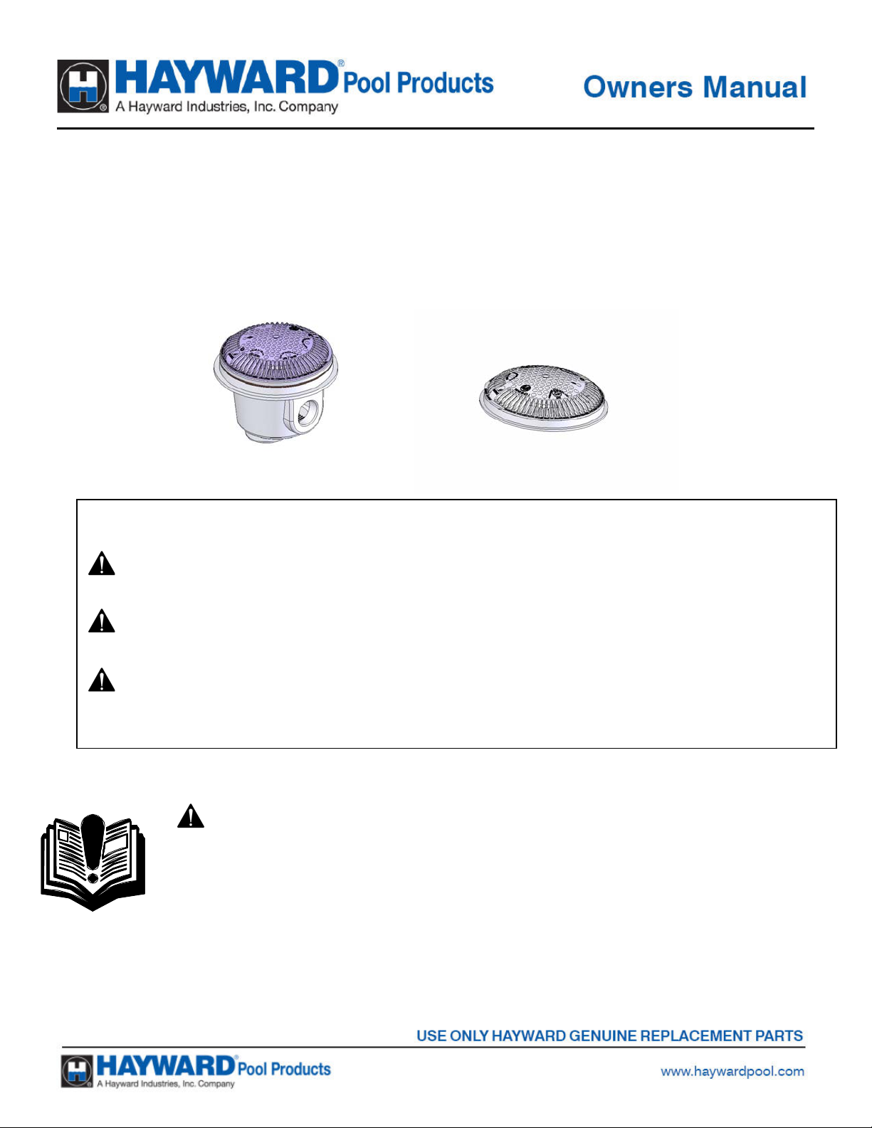
DUAL SUBMERGED SUCTION OUTLET SET
[Commonly called main drains]
Basic safety precautions should always be followed, including the following: Failure to follow instructions can cause severe
injury and/or death.
This is the safety-alert symbol. When you see this symbol on your equipment or in this manual, look for one of the
following signal words and be alert to the potential for personal injury.
WARNING warns about hazards that could cause serious personal injury, death or major property damage and if
ignored presents a potential hazard.
CAUTION warns about hazards that will or can cause minor or moderate personal injury and/or property damage
and if ignored presents a potential hazard. It can also make consumers aware of actions that are unpredictable and unsafe.
The NOTICE label indicates special instructions that are important but not related to hazards.
- WARNING - Read and follow all instructions in this
owner’s manual and on the equipment. Failure to follow
instructions can cause severe injury and/or death.
IMPORTANT SAFETY INSTRUCTIONS
Page 2
Page 2 of 8 DUAL SUCTION OUTLET SET ISDUALSWG REV D
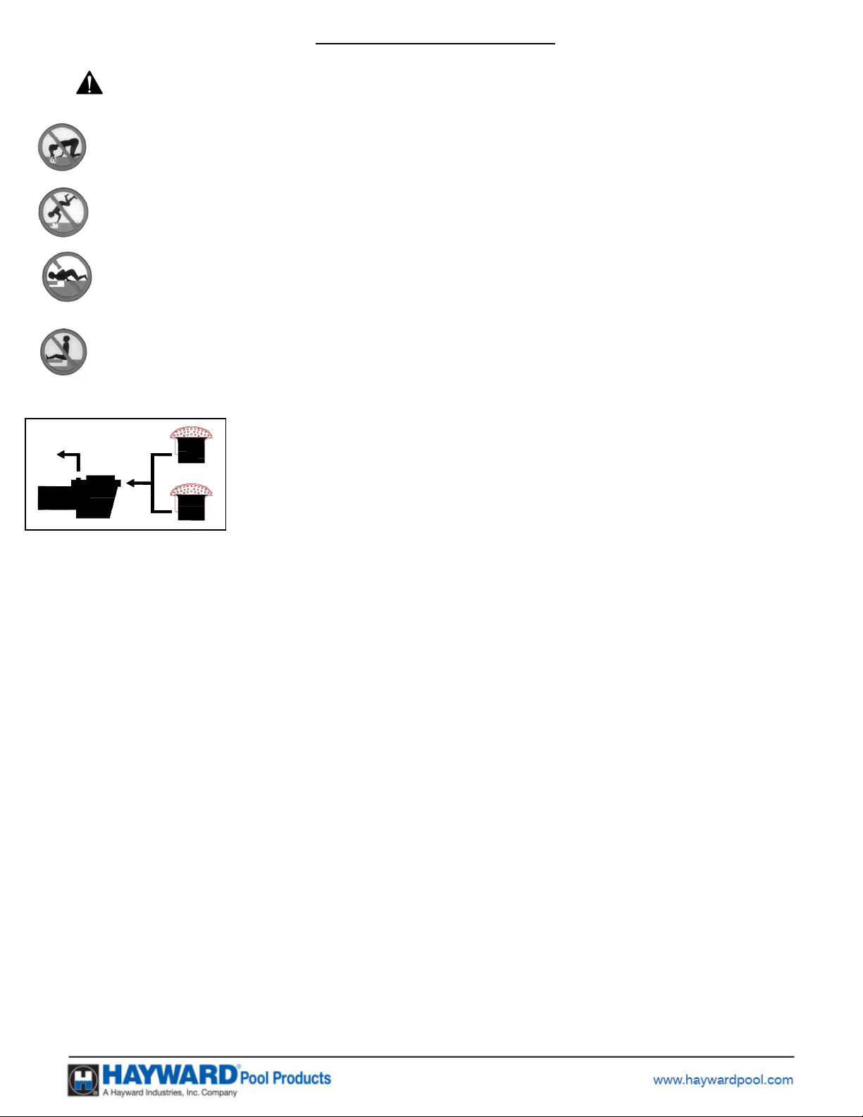
WARNING – Suction Entrapment Hazard.
Suction in suction outlets and/or suction outlet covers which are damaged, broken, cracked, missing,
or unsecured can cause severe injury or death due to the following entrapment hazards:
Hair Entrapment- Hair becomes knotted or snagged in an outlet cover.
Limb Entrapment- A limb sucked or inserted into an opening of a circulation outlet with a broken or
missing cover in the pool resulting in a mechanical bind or swelling
Body Suction Entrapment- Suction applied to a large portion of the body or limbs resulting in an
entrapment.
Evisceration/ Disembowelment Entrapment- Suction applied directly to the intestines through an
unprotected sump or suction outlet with a missing or broken cover.
Mechanical Entrapment
be caught in an opening of an outlet or cover.
- Potential for jewelry, swimsuit, hair decorations, finger, toe or knuckle to
To Reduce the risk of Entrapment Hazards:
o A minimum of two functioning suction outlets per pump must be installed.
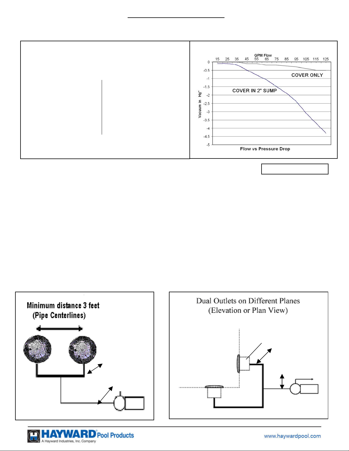
Suction outlets in the same plane (i.e. floor or wall), must be installed a
minimum of three feet (3’) [.91 meter] apart, as measured from suction pipe
center to suction pipe center. (See Diagram 1. If suction outlets are to be located
closer then three feet (3’) [.91 meter] apart, they shall be located in different
planes (i.e., one on the bottom, and one on the vertical wall, or one on each of
two separate vertical walls.) (See Diagram 2)
o Dual suction fittings shall be placed in such locations and distances to avoid “dual blockage” by a
user.
o Dual suction fittings shall not be located on seating areas or on the backrest for such seating areas.
o The maximum system flow rate shall not exceed the flow rating of any listed (per ASME/ANSI
A112.19.8M-1987, ASME A112.19.8-2007, APSP-7) suction outlet cover installed.
o Keep suction outlet components clear of debris, such as leaves, dirt, hair, paper and other material.
o Never use a Pool or Spa if any suction outlet component is damaged, broken, cracked, missing, or not
securely attached.
o Prior to each use of the swimming pool and/or spa, observe and replace damaged, broken, cracked,
missing, or not securely attached suction outlet components immediately.
o Remove pressure test plugs and/or plugs used in winterization of the pool/spa from the suction outlets.
o Two or more suction outlets per pump should be installed in accordance with latest APSP Standards
and CPSC guidelines. Follow all National, State, and Local codes applicable.
o Multiple layers of protection are available including installation of a vent pipe system, a gravity flow
system, or a vacuum release system.
o
Suction outlet components have a finite life, the cover/grate should be inspected frequently and
replaced at least every seven years or if found to be damaged, broken, cracked, missing, or not
securely attached.
o
Do not exceed maximum flow rate stated on suction fitting.
o Only replace a pump with one with a similar flow curve, avoid a pump with a higher horsepower
rating.
Page 3
Page 3 of 8 DUAL SUCTION OUTLET SET ISDUALSWG REV D
d
N
• RECOMMENDED SYSTEM SPECIFICATIONS:
ACCEPTABLE PIPE SIZE FOR MAXIMUM
RECOMMENDED
SYSTEM FLOW RATE PER APSP-7
(6 FT/SEC IN THE BRANCH LINE)
Pipe Size
[mm]
1 ½”
[50]
Flow rate
GPM
[Liter/Min]
40
[150]
Pipe Size
[mm]
2 ½”
[75]
Flow rate
GPM [Liter/Min]
90
[340]
2”
[63]
63
[240]
3”
[90]
138
[522]
Chart 1
WGX1048E Suction Outlet Covers are rated for Floor Only at 125 GPM
FIG 1
ote: 1” Hg = 1.13 Ft of Head
WG1048EW Suction Outlet Covers are rated for Wall or Floor at 72 GPM
In the event of one suction outlet being blocked, the remaining suction outlets serving that system shall have a
flow rating capable of the full flow of the pump(s) for the specific suction system.
Example: In the System shown in Diagram 1, two (2) “Floor Only” suction outlet covers are selected and mounted.
These covers are individually rated for 125 GPM. For a desired flow rate through the pump of 100 GPM, a minimum
pipe size from the Chart 1 is selected at 3”. At the desired flow of 100 GPM one cover could be partially blocked
and the other suction outlet flow would be below the rated 125 GPM of the “Floor” mounted suction outlet cover.
Since there are two outlets flowing in normal operation, and the allowable velocity in the interconnecting piping is
only 3ft/sec, the same pipe size is required in the interconnecting piping.
Example: In the System shown in Diagram 2, one (1) “Floor Only” suction outlet cover, rated at 125 GPM, and one (1)
“Wall or Floor” suction outlet cover, rated at 72 GPM are selected and mounted. For a desired flow rate through the
pump of 50 GPM, a minimum pipe size from the Chart 1 is selected at 2”. At the desired flow of 50 GPM either
cover could be totally blocked and the other suction outlet flow would be below the rated 72 GPM of the wall
mounted suction outlet cover. Note: Flow may be limited by entrapping force in dual suction systems.
Floor Outlets,
Total syste m rated
flow 125 GPM
Interconnecting
piping
System
Branch piping
Total System rated
flow 72 GPM
125 GPM Rated
Wall
72 GPM rate
Interconnecting
piping
System branch piping
Diagram 2
Diagram 1
Page 4

Page 4 of 8 DUAL SUCTION OUTLET SET ISDUALSWG REV D
INSTALLATION INSTRUCTIONS: - Use a #2 Philips head Screwdriver.
NOTICE: When installing WG1030AVPAK2 refer to ASME A112.19.8-2007 for the proper instructions on
how to construct the field-fabricated sump. Figure 2 is an illustration of some of the requirements.
Suction outlets for a pool with a vinyl liner and for fiberglass pools are provided with a WG1048B mounting
ring and two (2) gaskets. The gaskets should be placed such that they sandwich the liner or fiberglass, that is,
one gasket on each side. The ring (WG1048B) is attached to the suction outlet by eight (8) screws that pass
through both gaskets and the liner. See diagram below.
Suction outlets for a concrete or gunite pools are
designed to be plastered with the top surface flush
to the pool surface. An Adjustable Collar
WG1051X may be used to aid in obtaining the
desired configuration.
Two screws MUST be used to secure the cover to
the suction outlet. USE ONLY HAYWARD GENUINE
REPLACEMENT PARTS INCLUDING THE SCREWS.
For installations utilizing a hydrostatic relief valve
(SP1056), using a collector tube (SP1055) will maintain a clear path to the hydrostatic valve. At least one
hydrostatic relief valve in a set of suction outlets will allow hydrostatic uplift pressure caused by ground water
to be relieved into the pool or spa.
Page 5

Page 5 of 8 DUAL SUCTION OUTLET SET ISDUALSWG REV D
g
g
• SPARE PARTS LISTS
WG1048AVPAK2/ WG1049AVPAK2
ITEM SPARE PART DESCRIPTION QTY
1 *WGX1030Z2A SCREW SET 1.0
COVER, SUCTION
2 **WGX1048E
2 **WG1048EW
3 WGX1048B
4 SPX1048D GASKET 2.0
5 SPX1051Z1
6 SPX1053Z1
7 SPX1039Z18 SCREW SET 1.0
NOTES:
WG1048AVPAK2 / WG1049AVPAK2 1 ½” NPT BottomPlu
WG1049AVPAK2 2” NPT Side Plug
*-SPARE SCREW SET INCLUDES SCREWS FOR SUMPS
WITHOUT METAL INSERTS. IF SUMP HAS METAL
INSERTS INSTALLED ADD (M) TO END OF PART NUMBER.
**-SPARE COVER INCLUDES SCREWS FOR ALL
VARIATIONS OF SUMPS, WITH OR WITHOUT METAL
INSERTS.
OUTLET
COVER, SUCTION
OUTLET
RING, SUCTION
OUTLET 1.0
1 1/2 IN PLASTIC
PIPE PLUG 1.0
2 IN PLASTIC PIPE
PLUG 1.0
1.0
1.0
WG1051AVPAK2/ WG1052AVPAK2/
WG1053AVPAK2/ WG1054AVPAK2
ITEM SPARE PART DESCRIPTION QTY
1 *WGX1030Z1A SCREW SET 1.0
COVER, SUCTION
2 **WGX1048E
2 **WG1048EW
3 SPX1051Z1
4 SPX1053Z1
NOTES:
WG1051AVPAK2 / WG1052AVPAK2 1 ½” NPT BottomPlu
WG1053AVPAK2 / WG1054AVPAK2 2” NPT Bottom Plug
*-SPARE SCREW SET INCLUDES SCREWS FOR SUMPS
WITHOUT METAL INSERTS. IF SUMP HAS METAL
INSERTS INSTALLED ADD (M) TO END OF PART NUMBER.
**-SPARE COVER INCLUDES SCREWS FOR ALL
VARIATIONS OF SUMPS, WITH OR WITHOUT METAL
INSERTS.
OUTLET 1.0
COVER, SUCTION
OUTLET
1 1/2 IN PLASTIC
PIPE PLUG
2 IN PLASTIC PIPE
PLUG 1.0
1.0
1.0
Page 6

Page 6 of 8 DUAL SUCTION OUTLET SET ISDUALSWG REV D
g
ITEM SPARE PART DESCRIPTION QTY
1 *WGX1030Z1A SCREW SET 1.0
COVER, SUCTION
WG1153AVPAK2/ WG1154AVPAK2
2 **WGX1048E
2 **WG1048EW
3 WGX1153B
4 SPX1051Z1
5 SPX1053Z1
NOTE:
SP1153AVPAK2 / SP1154AVPAK2 2” NPT BottomPlu
*-SPARE SCREW SET INCLUDES SCREWS FOR SUMPS
WITHOUT METAL INSERTS. IF SUMP HAS METAL
INSERTS INSTALLED ADD (M) TO END OF PART NUMBER.
**-SPARE COVER INCLUDES SCREWS FOR ALL VARIATIONS
OF SUMPS, WITH OR WITHOUT METAL INSERTS.
OUTLET 1.0
COVER, SUCTION
OUTLET
EXTENSION
COLLAR 1.0
1 1/2 IN PLASTIC
PIPE PLUG
2 IN PLASTIC PIPE
PLUG
1.0
1.0
1.0
ITEM SPARE PART DESCRIPTION QTY
SCREW SET (8"
1 *WGX1030Z1A
2 **WGX1048E
2 **WG1048EW
3 WGX1058C ROUND FRAME 1.0
ROUND)
COVER, SUCTION
OUTLET 1.0
COVER, SUCTION
OUTLET
1.0
1.0
*-SPARE SCREW SET INCLUDES SCREWS FOR SUMPS
WITHOUT METAL INSERTS. IF SUMP HAS METAL INSERTS
INSTALLED ADD (M) TO END OF PART NUMBER.
WG1030AVPAK2
**-SPARE COVER INCLUDES SCREWS FOR FRAME, WITH OR
WITHOUT METAL INSERTS.
SEE NOTICE ON PAGE 3 FOR FIELD FABRICATED OUTLETS
SAVE THESE INSTRUCTIONS FOR
FUTURE REFERENCE.
Page 7

Page 7 of 8 DUAL SUCTION OUTLET SET ISDUALSWG REV D
This equipment was inspected before shipment from our plant. To original purchasers of this equipment,
Hayward Pool Products, 620 Division Street, Elizabeth, New Jersey, warrants its products free from defects
in materials and workmanship for a period of ONE (1) year from the date of purchase.
Parts which fail or become defective during the warranty period, except as a result of freezing, negligence,
improper installation, use, or care, shall be repaired or replaced, at our option, without charge, within 90 days
of the receipt of defective product, barring unforeseen delays.
To obtain warranty replacements or repair, defective components or parts should be returned, transportation
paid, to the place of purchase, or to the nearest authorized Hayward service center. For further Hayward
dealer or service center information, contact Hayward customer service department. No returns may be made
directly to the factory without the express written authorization of Hayward Pool Products
To original purchasers of this equipment, Hayward Pool Products warrants its vacuum release systems to be
free from defects in materials and workmanship for a period of ONE (1) year from the date of purchase.
Vacuum Release Systems which become defective during the warranty period, except as a result of freezing,
negligence, improper installation, use or care, shall be repaired or replaced, at our option, without charge.
All other conditions and terms of the standard warranty apply.
Hayward shall not be responsible for cartage; removal and/or reinstallation labor or any other such costs
incurred in obtaining warranty replacements.
The Hayward Pool Products warranty does not apply to components manufactured by others. For such
products, the warranty established by the respective manufacturer will apply.
Some states do not allow a limitation on how long an implied warranty lasts, or the exclusion or limitation of
incidental or consequential damages, so the above limitation or exclusion may not apply to you.
This warranty gives you specific legal rights, and you may also have other rights, which vary from state to
state.
HAYWARD® LIMITED WARRANTY
Page 8

Page 8 of 8 DUAL SUCTION OUTLET SET ISDUALSWG REV D
PRODUCT REGISTRATION
(Retain For Your Records)
DATE OF INSTALLATION ____________________
▲Retain this Warranty Certificate (upper portion) in a safe and convenient location for your records.
DETACH HERE: Fill out bottom portion completely and mail within 10 days of purchase/installation, OR REGISTER YOUR WARRANTY
ONLINE AT WWW.HAYWARDNET.COM
Dual Suction Outlet Set
 Loading...