

HAYWARD VR1000 service manual
PN: ISVR1000TECH Rev: J
_____________________________________________________________________________________________________________________________________
MODEL VR1000
SERVICE MANUAL
INSTALLATION & PARTS
WARNING – Improper installation, use, or maintenance of this Vacuum Release System or associated
equipment could cause serious or fatal injury. To reduce the risk of injury, read and follow all instructions in this
Manual and on the equipment. Make sure installation and any maintenance necessary are done by people who are
qualified and have the proper equipment to do the job right. All electrical wiring MUST be in conformance with
all applicable local codes, regulations, and the National Electrical Code (NEC).
Basic safety precautions should always be followed, including the following: Failure to follow instructions can cause severe
injury and/or death.
This is the safety-alert symbol. When you see this symbol on your equipment or in this manual, look for one of the
following signal words and be alert to the potential for personal injury.
WARNING warns about hazards that could cause serious personal injury, death or major property damage and if
ignored presents a potential hazard.
CAUTION warns about hazards that will or can cause minor or moderate personal injury and/or property damage
and if ignored presents a potential hazard. It can also make consumers aware of actions that are unpredictable and unsafe.
The NOTICE label indicates special instructions that are important but not related to hazards.
USE ONLY HAYWARD GENUINE REPLACEMENT PARTS
Pomona, CA Clemmons, NC Nashville, TN
Tel: 908.351.5400 www.haywardpool.com
Page 2 of 24 STRATUM™ Model VR1000 P/N: ISVR1000TECH Rev: J
READ AND FOLLOW ALL INSTRUCTIONS IN THIS SERVICE AND
INSTALLATION MANUAL AND ON EQUIPMENT.
IMPORTANT SAFETY INSTRUCTIONS
Before installing or servicing this electrical equipment, turn power supply OFF.
KEEP SAFETY LABELS IN GOOD CONDITION AND
WARNING – To reduce risk of injury, do not permit children to use or climb on the pumps and filters. Closely supervise children at all
times. Components such as the filtration system, pumps, and heaters must be positioned to prevent children from using them as a means of access to
the pool.
REPLACE IF MISSING OR DAMAGED.
CAUTION – This vacuum release system is intended for use on permanently installed swimming pools and may also be used with hot
tubs and spas. Do NOT use with storable pools. A permanently installed pool is constructed in or on the ground or in a building such that it cannot
be readily disassembled for storage. A storable pool is constructed so that it is capable of being readily disassembled for storage and reassembled to
its original integrity.
Though this product is designed for outdoor use, it is strongly recommended to protect the electrical components from the weather. Select a welldrained area, one that will not flood when it rains. It requires free circulation of air for cooling. Do not install in a damp or non-ventilated location. If
installed within an outer enclosure or beneath the skirt of a hot tub or spa, adequate ventilation and free circulation of air must be provided to prevent
overheating of the components
.
WARNING – All electrical wiring MUST be in conformance with all applicable local codes, regulations, and the National
Electrical Code (NEC). Risk of Electric Shock. Hazardous voltage can shock, burn, cause death or serious property damage. To
reduce the risk of electric shock, do NOT use an extension cord to connect unit to electric supply. Provide a properly located outlet.
All electrical wiring MUST be in conformance with applicable local and national codes and regulations. Before working on pump or
motor, turn off power supply to the pump.
WARNING – To reduce the risk of electric shock replace damaged wiring immediately. Locate conduit to prevent abuse from lawn
mowers, hedge trimmers and other equipment.
WARNING – All electrical wiring MUST be in conformance with all applicable local codes, regulations, and the National Electrical Code
(NEC) including a Ground Fault Circuit Interrupter (GFCI) in circuit. For size of GFCI required and test procedures for GFCI, see manufacturer’s
instructions. Pump MUST be permanently connected to GFCI.
WARNING – Failure to bond pump to pool structure will increase risk for electrocution and could result in injury or death. To reduce the
risk of electric shock, the electrician must comply with installation instructions and must bond the pump accordingly. In addition, the electrician
must also conform to local electrical codes for bonding requirements.
Notes to the electrician:
Use a solid copper conductor, size 8 or larger. Run a continuous wire from external bonding lug to reinforcing rod or mesh. Connect a No. 8 AWG
(8.4 mm
hot tub, and to all electrical equipment, metal piping (except gas piping), and conduit within 5 ft. (1.5 m) of inside walls of swimming pool, spa, or
hot tub. IMPORTANT - Reference NEC codes for all wiring standards including, but not limited to, grounding, bonding and other general wiring
procedures. NOTE - The National Electrical Code (NEC) permits use of a cord with a maximum 3 ft. (1 m) length. If your pump is equipped with a
cord complying with the NEC, the preceding four (4) hazards apply.
2
) solid copper bonding wire to the pressure wire connector provided on the motor housing and to all metal parts of swimming pool, spa, or
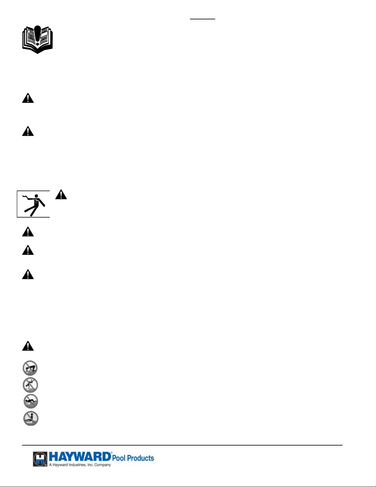
WARNING – Suction Entrapment Hazard.
Suction in suction outlets and/or suction outlet covers which are, damaged, broken, cracked, missing, or unsecured can cause severe injury
and/or death due to the following entrapment hazards:
Hair Entrapment- Hair can become entangled in suction outlets.
Limb Entrapment- A limb inserted into an opening of a suction outlet or suction outlet cover that is damaged, broken, cracked, missing,
or not securely attached can result in a mechanical bind or swelling of the limb.
Body Suction Entrapment- A differential pressure applied to a large portion of the body or limbs can result in an entrapment.
Evisceration/ Disembowelment - A negative pressure applied directly to the intestines through an unprotected suction outlet sump or
suction outlet cover which is damaged, broken, cracked, missing, or unsecured can result in evisceration (disembowelment).
Mechanical Entrapment- There is potential for jewelry, swimsuit, hair decorations, finger, toe or knuckle to be caught in an opening of a
suction outlet or suction outlet cover resulting in mechanical entrapment.
USE ONLY HAYWARD GENUINE REPLACEMENT PARTS
Pomona, CA Clemmons, NC Nashville, TN
Tel: 908.351.5400 www.haywardpool.com
Page 3 of 24 STRATUM™ Model VR1000 P/N: ISVR1000TECH Rev: J
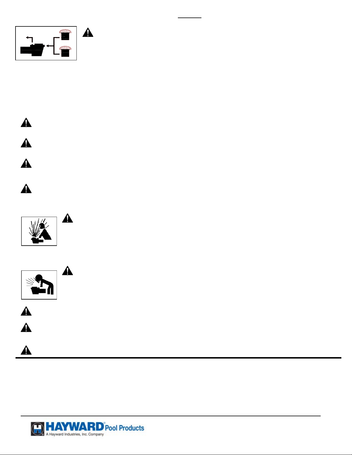
WARNING - To reduce the risk of entrapment hazards:
o When suction outlets are less than a 18” x 23” equivalent, a minimum of two functioning ASME112.19.8 suction
outlets per pump must be installed. Suction outlets in the same plane (i.e. floor or wall), must be installed a
minimum of three feet (3’) [1 meter] apart, as measured from near point to near point .
o Dual suction outlets shall be placed in such locations and distances to avoid “dual blockage” by a user.
o Dual suction fittings shall not be located on seating areas or on the backrest for such seating areas.
o The maximum system flow rate shall not exceed the flow rating of any listed (per current revision of ASME/ANSI A112.19.8) suction
outlet cover installed.
o Never use the Pool or Spa if any suction outlet component is damaged, broken, cracked, missing, or not securely attached.
o Replace damaged, broken, cracked, missing, or not secure ly attached suction outlet components immediately.
o In addition two or more suction outlets per pump installed in accordance with latest APSP (formally NSPI) Standards and CPSC
guidelines, follow all National, State, and Local codes applicable.
This vacuum release system is designed to prevent body suction entrapment, but not evisceration.
WARNING – Failure to remove pressure test plugs and/or plugs used in winterization of the pool/spa from the suction outlets can
result in an increase potential for suction entrapment as described above.
WARNING – Failure to keep suction outlet components clear of debris, such as leaves, dirt, hair, paper and other material can
result in an increase potential for suction entrapment as described above.
WARNING – Suction outlet components have a finite life, the cover/grate should be inspected frequently and replaced at least
every ten years or if found to be damaged, broken, cracked, missing, or not securely attached.
WARNING – All suction and discharge valves MUST be OPEN when starting the circulation system. Failure to do so could result in
severe personal injury and/or property damage. All drains and suction outlets MUST have properly installed covers, securely attached using the
screws supplied with the covers. If screws are lost, order replacement parts from your supplier.
WARNING – Hazardous Pressure. Pool and spa water circulation systems operate under hazardous pressure during
start up, normal operation, and after pump shut off. Stand clear of circulation system equipment during pump start up. Failure to
follow safety and operation instructions could result in violent separation of the pump housing and cover due to pressure in the
system, which could cause property damage, severe personal injury, or death. Before servicing pool and spa water circulation
system, all system and pump controls must be in off position and filter manual air relief valve must be in open position. Before
starting system pump, all system valves must be set in a position to allow system water to return back to the pool. Do not change
filter control valve position while system pump is running. Before starting system pump, fully open filter manual air relief valve.
Do not close filter manual air relief valve until a steady stream of water (not air or air and water) is discharged.
WARNING – Separation Hazard. Failure to follow safety and operation instructions could result in violent
separation of pump components. Strainer cover must be properly secured to pump housing with strainer cover lock ring. Before
servicing pool and spa circulation system, manual air relief valve must be in open position. Do not operate pool and spa
circulation system if a system component is not assembled properly, damaged, or missing. Do not operate pool and spa
circulation system unless filter air relief valve body is in locked position in filter upper body.
WARNING – Never operate or test the circulation system at more than 40 PSI.
WARNING – Fire and burn hazard. Motors operate at high temperatures and if they are not properly isolated from any flammable
structures or foreign debris they can cause fires, which may cause severe personal injury or death. It is also necessary to allow the motor to cool for
at least 20 minutes prior to maintenance to minimize the risk of burns.
WARNING – Failure to install according to defined instructions may result in severe personal injury or death.
DEFINITIONS:
Suction Outlet – The term Suction Outlet is a fitting, fitting assembly, cover/grate and related components that provide a means for water to exit the
pool and into the pump circulating system.
Inches of Mercury (in Hg) - A unit for measuring pressure below atmospheric (“suction” or “vacuum”) (1.0 inch Hg = .491 PSI)
Main Drain – See Suction Outlet
PSI – An abbreviation for pounds per square inch.
USE ONLY HAYWARD GENUINE REPLACEMENT PARTS
Pomona, CA Clemmons, NC Nashville, TN
Tel: 908.351.5400 www.haywardpool.com
Page 4 of 24 STRATUM™ Model VR1000 P/N: ISVR1000TECH Rev: J
General Information:
The VR1000 Vacuum Release System is designed as a pump controller. The system will protect pool and spa equipment from certain
known mechanical failures, such as clogged drains and pipe breakage; which can cause premature pump motor failure. The system
monitors and recognizes a change in pressure and electrical power. When a change occurs, it will shut down the pump, and vent the
suction line. Automatic soft start should provide notice to swimmers or bathers on pump startup. The VR1000 meets the
requirements of ASTM Specification F2387-04. Meets ASME Standard 112.19.17. Meets UL standard 1563 as well as certified to
Can/CSA Std. C27.2 No. 218.1.
The VR1000 system will automatically restart in most instances. Should a manual restart be required, pressing the “OK” button will
restart the system
30 minutes, providing NO protection for sw immers or bathers. DO NOT ALLOW SWIMMERS OR BATHERS IN THE PO OL OR
SPA WHEN THE SYSTEM IS IN “UNPROTECTED” MODE.
For proper installation and to avoid unnecessary service calls, read this manual carefully and completely.
. “Unprotected” Mode can be entered, after restart, by holding “NO” & “OK” buttons. “Unprotected” mode lasts
WARNING – This product should be installed and serviced only by a qualified professional. Failure to install and/or
operate according to defined instructions and/or use of non-Hayward replacement parts will void the warranty.
CAUTION – All electrical wiring MUST be in conformance with all applicable local codes, regulations, and the National
Electrical Code (NEC).
Introduction:
This manual contains information for the proper installation and operation of the Hayward VR1000 Vacuum Release System.
The instructions in this manual MUST be followed precisely.
NOTICE – ALL PRESSURE TESTING OF THE SYSTEM MUST BE COMPLETED BEFORE
NOTICE – The filter must be cleaned or cartridge replaced before installing the STRATUM™.
NOTICE –The STRATUM™ is rated for 115 VAC 50/60Hz for up to a 1 horsepower pump motor or 208/230
INSTALLING THE STRATUM™.
VAC 50/60Hz for up to a 3 horsepower pump motor.
FIG 1
USE ONLY HAYWARD GENUINE REPLACEMENT PARTS
Pomona, CA Clemmons, NC Nashville, TN
Tel: 908.351.5400 www.haywardpool.com
Page 5 of 24 STRATUM™ Model VR1000 P/N: ISVR1000TECH Rev: J
Installation Instructions
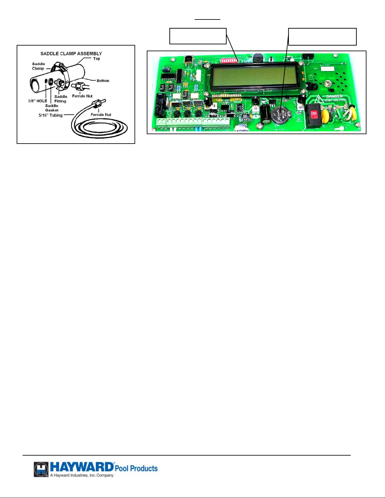
DIP Switches Battery BR2032
FIG 2.
LIST OF NEEDED ITEMS FOR INSTALLATION
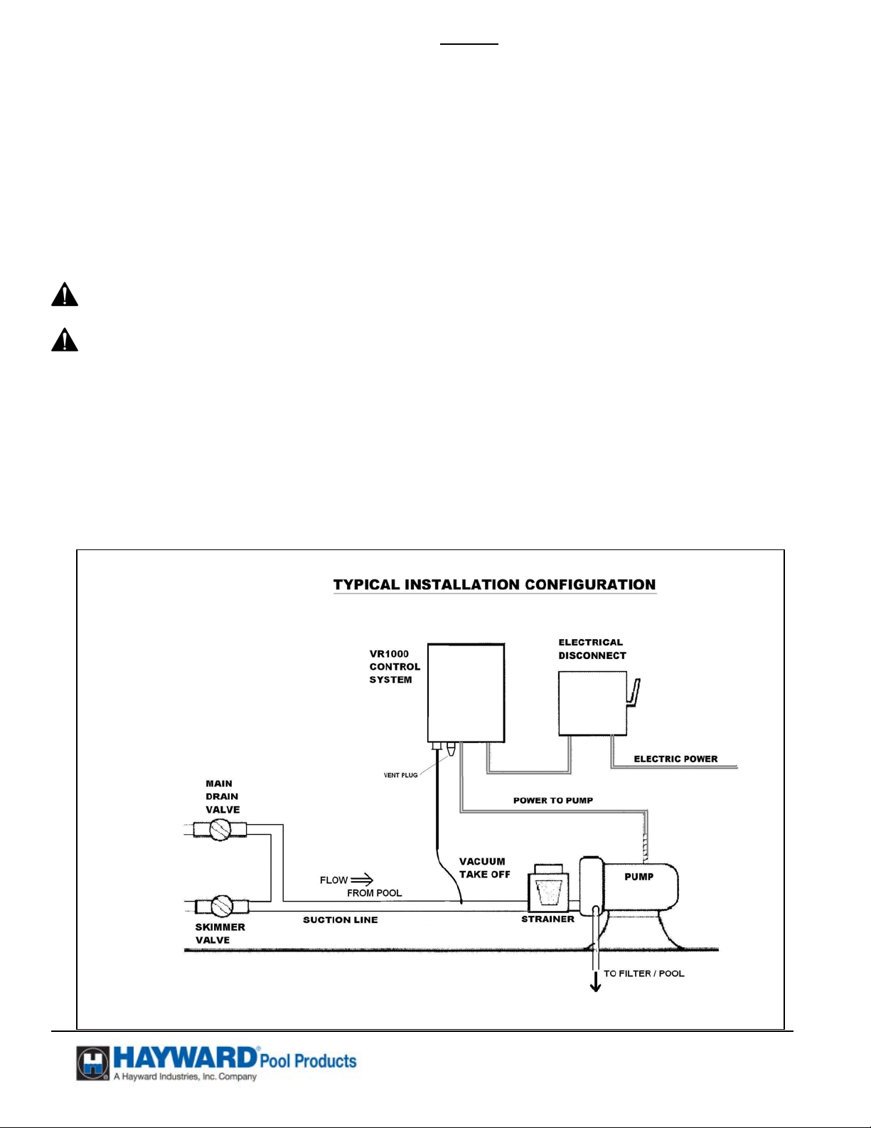
1. VR1000 system
2. Location on vertical surface to install the VR1000 within ten feet of the pump and above the pump.
3. 25’ length of tubing (Supplied in package.)
4. For Pipe installation,
a. 3/8” electric drill
b. 3/8” drill bit
c. Saddle Gasket CL220C (Supplied in package.)
d. Saddle Fitting CL220G (Supplied in package.)
e. Saddle Clamp CL220K (Supplied in package.)
f. Ferrule Nut and Ferrule (Supplied in package.)
5. Adjustable wrench
6. #2 Phillips screw driver
7. Small bladed screw driver
8. Large bladed screw driver
Mounting hardware for VR1000 Electrical box (Not Supplied)
MECHANICAL MOUNTING INSTRUCTIONS FOR INGROUND POOLS WITHOUT FLOODED SUCTION.
Note: If the installation is for an above ground pool or for flooded suction, the VRX100F assembly is suggested.
The VR1000 is designed to be used on a single pump or a combination of a single pump with a booster pump, on a
common suction line.
1. TURN OFF THE ELECTRICAL POWER AT THE CIRCUIT BREAKER.
2. Remove all check valves from the suction lines of the Pool/Spa system.
WARNING- Check Valves must be removed from the circulation systems. The presence of a check valve used to
carry the water flow within the circulation system has been shown to prolong the high vacuum present at the
drain, even though the drain is protected by a SVRS. For this reason, check valves which carry the water flow
within the circulation system must be removed.
3. For installation of the vacuum sensing tube into the suction line of the pump: (See Page 17 for additional pictures)
a. Locate a straight section of pipe approximately one foot long, as close to the inlet of the pump as practical.
b. On this straight pipe about in the middle, go 45º from the top. (This will minimize the air entrapment in the system
and help keep the system stable.) Drill a 3/8” hole. (See FIG 2)
c. Install the Saddle Gasket on the end of the Saddle fitting. Place the assembly in the drilled hole. Place the saddle
clamp over the saddle fitting. Tighten the Saddle clamp to assure a leak free joint. DO NOT OVERTIGHTEN.
4. Find a location for the VR1000 on a wall, or post, out of the direct sunlight, which will not be flooded, and above the pump.
If the box is mounted below the water level, the vent should be extended to above the water level.
5. Place the Ferrule Nut over the tubing. (See FIG 2) Make sure the tubing bottoms out in the saddle fitting. Holding the
tubing in place, tighten the Ferrule Nut firmly by hand. DO NOT OVERTIGHTEN. Run the 5/16” vacuum tube from the
fitting on the suction line to the fitting on the VR1000 unit. Make sure the vacuum tubing has no kinks and is strain free.
The fitting on the STRATUM™ does not require tooling to install the tubing. Just insert the end of the tubing firmly into the
fitting, a slight pull should not dislodge the tubing.
USE ONLY HAYWARD GENUINE REPLACEMENT PARTS
Pomona, CA Clemmons, NC Nashville, TN
Tel: 908.351.5400 www.haywardpool.com

Page 6 of 24 STRATUM™ Model VR1000 P/N: ISVR1000TECH Rev: J
INITIAL REQUIRED SETTINGS:
1. The VR1000 unit is factory set for 230VAC input. Leave the switch in this “FACTORY SET” position unless a low voltage
error occurs, in which case turn the power off, and move the switch to 115VAC.
2. NOTICE: THE CIRCUIT BOARD AND COMPONENTS MAY BE DAMAGED IF 208/230 VAC IS APPLIED TO
THE BOARD WHEN THE “SWITCH” IS IN THE 115VAC POSITION.
3. The VR1000 is factory set to English, the following three language settings are available by adjusting the dip switches 1, 2 at
the top of the board: A “ON” setting is down and toward the board. Please use a pen or pencil to gently move the switch as
required. See Fig 3
Language 1 2 3 4 5 6 7 8
English OFF OFF 2-Speed Pump Timers Manufacturing Test Booster Pump Specials Pinch Test
Spanish ON OFF
French OFF ON
4. To activate the component test, set Dip Switch 5 to ON. (This should NEVER be done unless directed to do so by Hayward
Technical Service.)
5. For 2 Speed pumps, set Dip Switch 3 to ON. Special wiring required. (See FIG 6)
6. To activate the timer cycle, set Dip Switch 4 to ON.
7. To activate the Booster Pump Timer, Set Dip Switch 6 to ON.
8. Dip Switch 7 is for Welded Contactor settings and High lift situations. (See Page 19) Must be set for flooded suction.
9. Dip Switch 8 performs special functions related to the detection of a pinched vacuum tube. After the pinched tube settings
have been made this switch should be turned to the OFF position to disable the screens (but not the function).
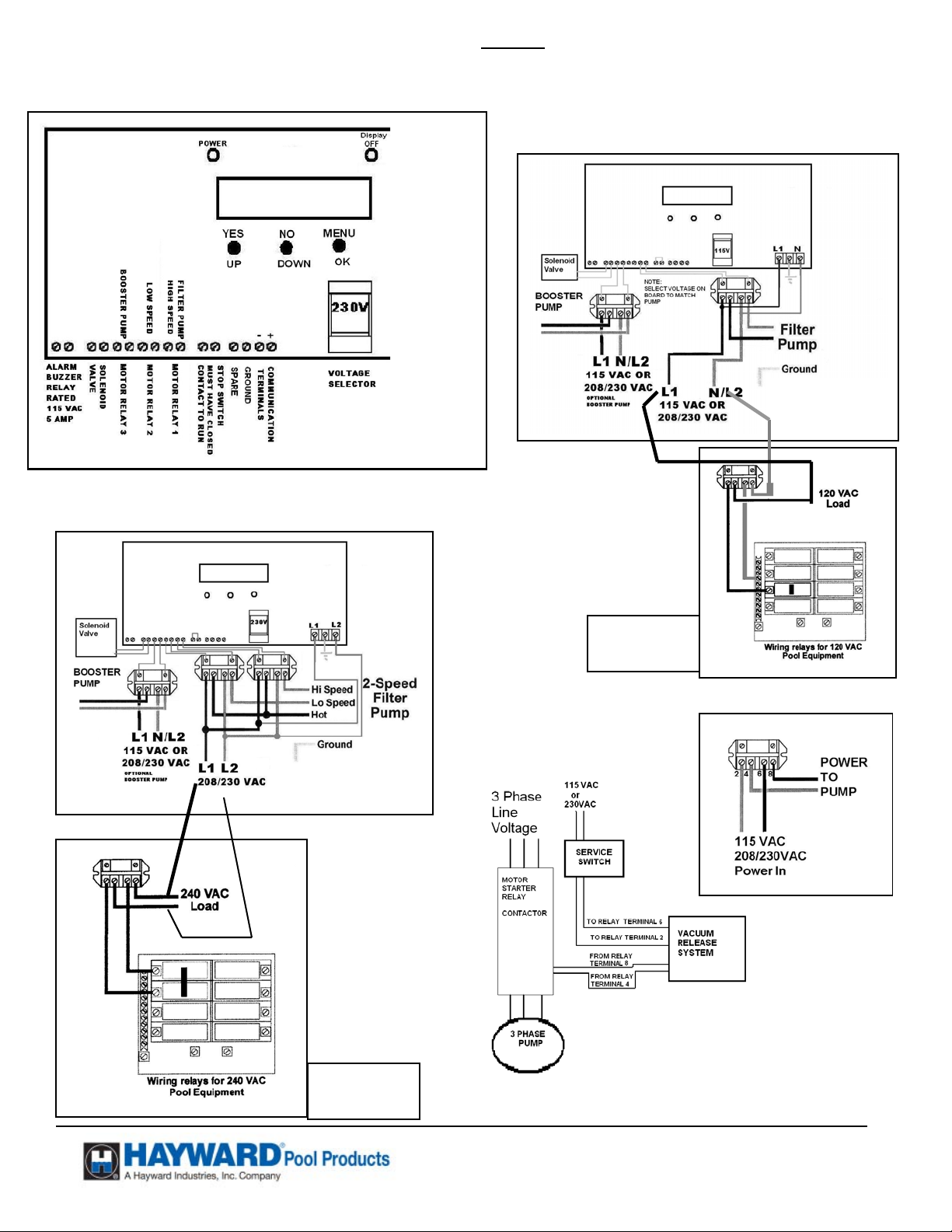
ELECTRICAL CONNECTION INSTRUCTIONS:
1. ASSURE POWER IS DISCONNECTED FROM SOURCE.
2. To install optional contactors the factory-installed wires attached must be connected to the proper terminals on the circuit
board. For a booster pump always use motor relay 3 on the board as shown in FIG. 4.
3. Connect pump to contactor terminals 4 & 8 (See FIG 7). If a booster pump is used, with a pool cleaner, connect this pump to
4 & 8 on a second contactor (Optional Contactor VRX100KIT). The contactor control (2 wires supplied) MUST be
connected onto the board next to the solenoid valve terminals, that is, in motor relay position 3. One reason to connect the
booster pump through this system is to protect the booster pump motor from burn out if the VR1000 were to stop the primary
filter pump. Additionally the timers can then be used to control the timing of the Booster pump.
4. If a two-speed pump is used connect the “Low Speed” to terminals 4 & 8 on a contactor (Optional Contactor VRX100KIT).
The contactor control (2 wires supplied) MUST be connected onto the board in motor relay position 2. NOTE: If the pump
horsepower is greater than 3 HP, the contactors can be used in series with the motor starters. (See Illustration below
FIG 8)
5. Connect a ground wire from the primary electrical panel to the VR1000 and connect the system to the pool bonding system
by an 8AWG (6AWG for Canada) wire. A lug for bonding is provided on the outside/bottom of the enclosure.
6. Connect incoming power to 2&6 on the power relay(s) (See FIG 7). Assure that the earth ground wire connector between the
conductors is secured.
7. (Optional) If a remote stop button is used, remove jumper from terminal pair marked “STOP Switch”. The switch must be a
“locking type “STOP” switch with a normally closed set of contacts in the “UP” position. Install the “STOP” switch across
the terminals where jumper was located. A Steward 28A0640-0A0-1/2 turn ferrite core or equal must be added to the stop
switch cable within 2” of the outside of the STRATUM™ box. (Stop switch can be Square D # KR9RH6 or equivalent
mounted in a rain tight box.)
8. (Optional) If a remote alarm is to be installed, the terminals “Buzzer” are connected to an alarm relay which will supply a
closed contact rated at 115 VAC, 5 amp, when the system alarm trips. External power must be supplied for the alarm to
sound. Can be used with Audible Alarms from Federal Signal Model 350-120-30 or equivalent available from Grainger.
9. The terminal marked “SPARE” when connected to the terminal marked “GROUND” will turn the pump on to “High Speed”
and maintain the “High Speed” mode until these two terminals are disconnected. Thus if a “Manual” override is desired a
maintained contact switch can be used to between these terminals.
10. For Flooded Suction and Pumps located more than 3’ above the pool turn on Dip Switch 7.(See Page 19)
11. Replace the inner barrier and secure with two screws included.
12. Power should be applied to the system while watching the display. Follow the directions on the display. This
operation will confirm the available voltage is suitable for proper operation of the VR system.
NOTICE: THE CIRCUIT BOARD AND COMPONENTS MAY BE DAMAGED IF 208/230VAC IS APPLIED TO THE
BOARD WHEN THE “SWITCH” IS IN THE 115VAC POSITION.
13. Close the electrical enclosure.
14. Apply power to system.
USE ONLY HAYWARD GENUINE REPLACEMENT PARTS
Pomona, CA Clemmons, NC Nashville, TN
Tel: 908.351.5400 www.haywardpool.com
Page 7 of 24 STRATUM™ Model VR1000 P/N: ISVR1000TECH Rev: J
FIG 5
Internal Control
FIG 4
FIG 6
Internal
Aqua Logic
Aqua Logic
FIG 7
FIG 8
THREE PHASE PUMP MOTOR
SUGGESTED CONNECTION
USE ONLY HAYWARD GENUINE REPLACEMENT PARTS
Pomona, CA Clemmons, NC Nashville, TN
Tel: 908.351.5400 www.haywardpool.com
Page 8 of 24 STRATUM™ Model VR1000 P/N: ISVR1000TECH Rev: J
N
Note: For Flooded Suction and Pumps installed more than 3’ above the surface of the pool Turn on Dip
Switch 7 before Appling power to the STRATUM™ (See Page 19)
VR1000 VER X.X
Initial Start OK
Initial Set-up
Complete? Y/N
INITIAL SCREENS: These will disappear after the Initial Set up is complete.
The start delay allows the installer to be ready for the system to start.
During initial start-up and set-up the start delay should not be disabled.
A press of the “OK” button will start the system.
Answering “YES” will allow the system to restart during normal operation.
Answering “No” will cause the system to come up to the “VR1000 VER XX Initial Start OK” screen
above and stop, when there is a loss of power.
SCREENS ON VR1000
For the set-up of the VR1000 we recommend that the system be placed in the “Unprotected mode”, which does not protected
swimmers or bathers from entrapment. It does allow the system to read the vacuum in various plumbing configurations.
HAYWARD POOL
PRODUCTS
Unprotected
Mode Entry Y/N
Press “NO” and “Menu” simultaneously and hold in until the screen changes to place system in
“Unprotected mode”.
Answer “Yes”.
Suction in suction outlets can cause severe injury and/or death due to a differential pressure applied to a large portion
of the body or limbs. STRATUM™ “Unprotected” Mode: Is when the pump is operating and the STRATUM™ is
NOT
and spa when the STRATUM™ is in “Unprotected” mode. The STRATUM™ only provides a layer of protection
against Body Suction Entrapment in monitoring mode.
o Swimmers Allow
In pool/Spa
Is Anyone in
Pool or Spa? Y/N
Unprotected Mode
Press OK to End
Unprotected Pool
Vacuum = X.X
Exiting
Unprotected Mode
WARNING - Body Suction Entrapment Hazard
providing any protection against Body Suction Entrapment. Do Not allow Swimmers and Bathers in the pool
NOTICE: The STRATUM™ will beep to indicate the unit is in unprotected mode.
Various configurations of the plumbing system for the Pool and Spa should be should be set-up with
the resulting vacuum level recorded. (See “Run and Record” Work Sheet page 17.)
Set up the Pool or Spa in the plumbing configuration that showed the lowest vacuum level for
column (B). This configuration should be used for the initiation of the VR1000.
Pressing “YES” will not allow activation mode and return you to the TECH Mode Screen
Pressing “No” will allow the system to go into “Unprotected” Mode for 30 minutes.
To stop “Unprotected” mode before the 30 minute period has expired press “OK”.
These two screens alternate and are for information purposes only.
USE ONLY HAYWARD GENUINE REPLACEMENT PARTS
Pomona, CA Clemmons, NC Nashville, TN
Tel: 908.351.5400 www.haywardpool.com
 Loading...