

Hayward TriStar SP3215VS Owner's Manual

30-LITINSB004 Rev-B
SAVE THIS INSTRUCTION MANUAL
Hayward Pool Products (Australia) Pty Ltd.
Melbourne-Sydney-Brisbane-Perth
Email: sales@hayward-pool.com.au Website: www.hayward-pool.com.au
P.O Box 4384, Dandenong South, VIC. 3164
ABN 66 083 413 414
Sales Ph 1300POOLS1 Fx 1300POOLS2
TriStar VS
®
NOTE: To prevent potential injury and to avoid unnecessary service calls,
read this manual carefully and completely.
The Hayward TriStar Variable Speed Pump is specifically engineered for the demanding
requirements of today’s in-ground swimming pool/spa that is equiped with large capacity
filters, heaters, and pool cleaning equipment. The variable speed, totaly enclosed
permanment magnet motor, combined with its advanced hydraulic design, optimizes the
three essiential pump elements to deliver superior flow, energy efficiency, and quietness.
3200 SERIES SELF-PRIMING
Model - SP3215VS
TriStar Variable Speed Pump
Owner’s Manual

Page 2
WARNING – Read and follow all instructions in this
owner’s manual and on the equipment. Failure to follow
instructions can cause severe injury and/or death.
WARNING – This product should be installed and serviced only by a qualified professional.
CAUTION – All electrical wiring MUST be performed by a qualified electrical contractor, and must conform
to local electrical regulations and AS/NZS 3000 Wiring Rules.
Use of non-Hayward replacement parts voids warranty.
ATTENTION INSTALLER – THIS MANUAL CONTAINS
IMPORTANT INFORMATION ABOUT THE
INSTALLATION, OPERATION, AND SAFE USE OF THIS PUMP THAT MUST BE FURNISHED TO THE END USER
OF THIS PRODUCT. FAILURE TO READ AND FOLLOW ALL INSTRUCTIONS COULD RESULT IN SERIOUS
INJURY.
CAUTION –
WARNING –
WARNING – Pool and spa components have a finite life. All components should be inspected frequently
and replaced at least every ten years, or if found to be damaged, broken, cracked, missing, or not securely attached.
This appliance is not intended for use by persons (including children) with reduced physical,
sensory or mental capabilities, or lack of experience and knowledge, unless they have been given supervision or
instruction concerning use of the appliance by a person responsible for their safety.
Children should be supervised to ensure that they do not play with the appliance.
This pump is intended for use on permanently installed swimming pools and may also be used
with hot tubs and spas if so marked. Do NOT use with storable pools. A permanently installed pool is constructed in
or on the ground or in a building such that it cannot be readily disassembled for storage. A storable pool is constructed
so that it is capable of being readily disassembled for storage and reassembled to its original integrity. Though this
product is designed for out door use, it is strongly advised to protect the electrical components from the weather.
Select a well-drained area, one that will not flood when it rains. It requires free circulation of air for cooling. Do not
install in a damp or non-ventilated location. If installed within an outer enclousere or beneath the skirt of a hot tub or
spa, adequate ventilation and free circulation of air must be provided to prevent overheating of the motor.
IMPORTANT SAFETY INSTRUCTIONS
Before installing or servicing this electrical equipment, turn power supply OFF.
WARNING – Risk of Electric Shock. All electrical wiring must be performed by a
qualified electrical contractor, and must conform to electrical regulations and AS 3000 Wiring
Rules. All electrical circuits must be supplied through a Residual Current Device - RCD
(Safety Switch), with a residual operating current of 30mA. Hazardous voltage can shock, burn
and cause death or serious property damage. To reduce the risk of electric shock, do NOT use
an extension cord to connect unit to the electricity supply.
WARNING – To reduce the risk of electric shock replace damaged wiring immediately. Locate the power
cord to prevent abuse from lawn mowers, hedge trimmers and other equipment.
WARNING – Never operate the circulation system at more than (50PSI) 344Kpa maximum.
WARNING – Automatic restart. The pump motor is automaticly protected from overload and overheating.
If such an error occurs the controller will automaticly try to restart the pump. If a power failure occurs while the pump
is running, it will automaticly restart once the power has been restored.
USE ONLY HAYWARD GENUINE REPLACEMENT PARTS
TriStar Variable Speed Pump
30-LITINSB004 Rev-B
Page 3
IMPORTANT SAFETY INSTRUCTIONS
Before installing or servicing this electrical equipment, turn power supply OFF.
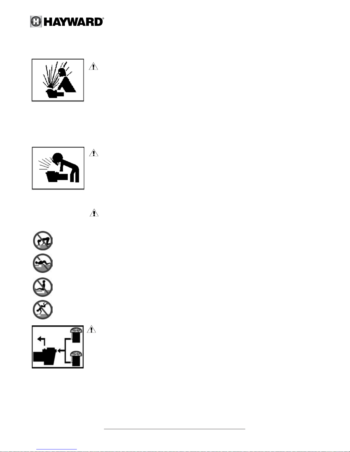
WARNING – Hazardous Pressure. Pool and spa water circulation systems operate
under hazardous pressure during start-up, normal operation, and after pump shut-off. Stand
clear of circulation system equipment during pump start-up. Failure to follow safety and
operation instructions could result in violent separation of the pump housing and cover due to
pressure in the system, which could cause property damage, severe personal injury, or death.
Before servicing pool and spa water circulation system, all system and pump controls must be
in the off position and the filter manual air relief valve must be in the open position. Before starting the system pump,
all valves must be set in a position to allow system water to return back to the pool. Do not change the filter control
valve position while the system pump is running. Before starting the system pump, fully open the filter manual air
relief valve. Do not close the filter manual air relief valve until all the air is expelled and a steady stream of water is
discharged from the valve. All suction and discharge valves MUST be OPEN when starting the circulation system.
Failure to do so could result in severe personal injury and/or property damage.
WARNING – Separation Hazard. Failure to follow safety and operation instructions
could result in violent seperation of pump components. Strainer cover must be properly secured
to pump housing with strainer cover lock ring. Before servicing pool and spa circulation system,
all system and pump controlls must be in off position and filter manual air relief valve must be in
open position. Do not operate pool and spa circulation system if system components are not
assembled properly, damaged, or missing. Do not operate pool and spa circulation system unless
filter air relief valve body is in locked position in filter upper body. All suction and discharge valves MUST be OPEN when
starting the circulation system. Failure to do so could result in severe personal injury and/or property damage.
WARNING - Suction Entrapment Hazard. Suction in suction outlets and/or
suction outlet covers, which are damaged, broken, cracked, missing, or unsecured cause sever injury and/or
death due to the following entrapment hazards.
Hair Entrapment - Hair can become entangled in suction outlet cover.
Limb Entrapment - A limb inserted into an opening of a suction outlet sump or suction outlet cover that is
damaged, broken, cracked, missing, or not securely attached can result in a mechanical bind or swelling of
the limb.
Body Suction Entrapment - A differential pressure applied to a large portion of the body or limbs can
result in an entrapment.
Evisceration/Disembowelment - A negative pressure applied directly to the intestines through an
unprotected suction outlet sump or suction outlet cover which is damaged, broken, cracked, missing, or
unsecured can result in evisceration/disembowelment.
Mechanical Entrapment - There is potential for jewelry, swimsuits, hair decorations, fingers, toes, or
knuckles to be caught in an opening of a suction outlet cover resulting in mechanical entrapment.
WARNING - To Reduce the risk of Entrapment Hazards:
- When outlets are small enough to be blocked by a person, a minimum of two functioning
suction outlets per pump must be installed. Suction outlets in the same plane (i.e. floor or wall),
must be installed a minimum of 0.91 metre or three feet (3’) apart, as measured from near point
to near point to avoid duel blockage by a user.
- Duel suction fittings shal not be located on seating areas or on the backrest for such seating
areas.
- Never use pool or spa if any suction outlet component is damaged, broken, cracked, missing, or not securely attached.
- Replace damaged, broken, cracked, missing, or not securely attached suction outlet components immediately.
- In addition to installing two or more suction outlets per pump, follow all national, state and local codes applicable.
- Installation of a vacuum release or vent system, which relieves entrapping suction, is recommended.
USE ONLY HAYWARD GENUINE REPLACEMENT PARTS
TriStar Variable Speed Pump
30-LITINSB004 Rev-B
Page 4
Introduction
This manual contains information for the proper installation and operation of the Hayward TriStar Variable Speed
Pump. The instructions in this manual MUST be followed precisely. Failure to install according to defined instructions
will void warranty.
Installation Instructions
WARNING – This product should be installed and serviced only by a qualified professional.
Pump Location
Locate pump as close to pool as practical and run suction lines as direct as possible to reduce friction
loss. Suction lines should have continuous slope upward from lowest point in line. Joints must be tight
(but not over-tightened). Suction line must not be less than 50mm in diameter and must be equal to
or larger in diameter than the discharge line diameter.
Though the pump is designed for outdoor use, it is advised to place pump and filter in the shade to shield them from
continuous direct heat. Select a well-drained area that will not flood when it rains. Do NOT install pump and filter in a
damp or non-ventilated location. Keep motor clean. Pump motors require free circulation of air for cooling.
Pump Mounting
Install pump on a level concrete slab or other rigid base to meet all local and national codes. Secure pump to base
with screws or bolts to further reduce vibration and stress on pipe joints. The base must be level, rigid, and vibration free.
Pump mount must:
• Allow pump inlet height to be as close to water level as possible.
• Allow use of short, direct suction pipe (to reduce friction losses).
• Allow for valves in suction and discharge piping.
• Be protected from excess moisture and flooding.
• Allow adequate access for servicing pump and piping.
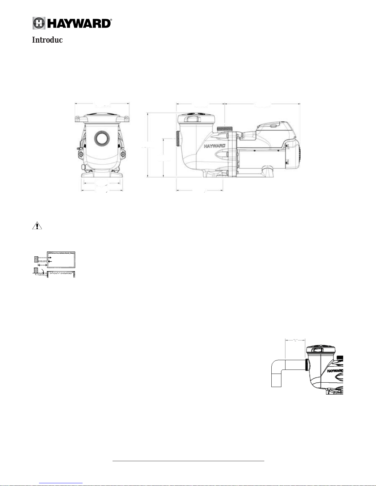
*NOTE: It is recommended that a minimum length of straight piping (shown as “L” in diagram to the right),
equivalent to 5 pipe size diameters, be used between the pump suction inlet and any plumbing fittings (elbows,
valves, ect).
USE ONLY HAYWARD GENUINE REPLACEMENT PARTS
TriStar Variable Speed Pump
Product Dimensions
293
194
222
344
206
249
259 315
*Note: All dimensions in millimetres
30-LITINSB004 Rev-B

Page 5
Electrical - specifications
The Variable Speed Drive is fully electronic. Consisting of an integrated power module (IPM) and controller, hard and
software with a digital signal processor (DSP). The mains inputs are supplied with a power factor correction (PFC) and
EMC filters. The Variable Speed Drive controls a Totaly Enclosed, Fan Cooled, Permanent Magnet Motor.
• Voltage: 220 - 240 VAC ± 10% of the mean rated voltage while running, 50Hz Single Phase
• Current: 5.9 amps
• Power (output): 1,100 W
• Speed Range: 600-3000 rpm
• Ambient temperature: 0 to 40°C
• Protection class: IP X5
All conductive parts within and around the pool shall be connected together by equipotential bonding conductors and
connected to the protective earthing conductor of the electrical equipment as stated in AS/NZS 3000.
USE ONLY HAYWARD GENUINE REPLACEMENT PARTS
TriStar Variable Speed Pump
Only use Teflon tape or an elastomeric thread sealant suitable for plastic, to seal threaded connections on moulded
plastic components. All plastic fittings must be new or thoroughly cleaned before use.
Note - Do Not use Plumbers Pipe Dope or or Plumbers Putty as it may cause cracking of the plastic components.
The pump suction and outlet ports have moulded in-thread stops. Do NOT attempt to force threaded connector fitting
past this stop. It is only necessary to tighten fittings enough to prevent leakage. Tighten fitting by hand and then use a
tool to engage the fitting an additional 1½ turns. Do NOT over-tighten fitting or you may cause damage. If a leak occurs,
remove the fitting and remove all traces of the sealing compound from thread. Re apply fresh sealing compound and
re-install the threaded fitting.
Note - If the pump is being installed using the standard Hayward Universal Union that is supplied with the pump
then there is no need to apply any type of thread sealant. The union gasket supplied is suffice to seal.
Fittings (elbows, tees, valves, ect.) restrict flow. For better efficiency use the fewest possible fittings. Avoid fittings that
could cause an air trap.
WARNING – Risk of Electric Shock. All electrical wiring must be performed by a qualified electrical
contractor, and must conform to electrical regulations and AS/NZS 3000 Wiring Rules. All electrical circuits must be
supplied through a Residual Current Device - RCD (Safety Switch), with a residual operating current of 30mA. Hazardous
voltage can shock, burn and cause death or serious property damage. To reduce the risk of electric shock, do NOT use
an extension cord to connect unit to the electricity supply, or if the supply cord is damaged, it must be replaced by the
manufacture, its service agent or similarly qualified persons in order to avoid a hazard.
Plumbing
Electrical
Bonding
WARNING - If circulation equipment must remain in the plumbing system during water pressure test, do
not apply more than 68 Kpa (10psi) pressure to the system. Be sure water pressure has been released, using the filter
manual air relief valve, before removing the pump strainer cover.
30-LITINSB004 Rev-B
 Loading...