

Page 1

Programming
and
User Manual
TLC Series
Read the User's Manual carefully before starting to use the unit or software.
Manufacturer reserves the right to implement changes without prior notice.
haywardowcontrol.com
REV2-1
Page 2
TLC Series
haywardowcontrol.com
REV2-2
Page 3
Explanation of symbols used in the manual:
This symbol denotes especially important guidelines concerning the installaon and operaon
of the device. Not complying with the guidelines denoted by this symbol may cause an accident,
damage or equipment destrucon.
IF THE DEVICE IS NOT USED ACCORDING TO THE MANUAL THE USER IS
RESPONSIBLE FOR POSSIBLE DAMAGES.
This symbol denotes especially important characteriscs of the unit. Read any informaon
regarding this symbol carefully.
1. BASIC REQUIREMENTS AND USER SAFETY
Do not use the unit in areas threatened with excessive shocks, vibraons, dust, humidity, corrosive gases and oils.
Do not use the unit in areas where there is risk of explosions.
Do not use the unit in areas with significant temperature variaons, exposure to condensaon or ice.
Do not use the unit in areas exposed to direct sunlight.
Make sure that the ambient temperature (e.g. inside the control box) does not exceed the recommended values. In such
cases forced cooling of the unit must be considered (e.g. by using a venlator).
TLC Series
The manufacturer is not responsible for any damages caused by inappropriate installaon, not maintaining the proper
environmental condions and using the unit contrary to its assignment.
Installaon should be conducted by qualified personnel . During installaon all available safety requirements should be
considered. The fier is responsible for execung the installaon according to this manual, local safety and EMC
regulaons.
GND input of device should be connected to PE wire;
The unit must be properly set-up, according to the applicaon. Incorrect configuraon can cause defecve operaon,
which can lead to unit damage or an accident.
If in the case of a unit malfuncon there is a risk of a serious threat to the safety of people or property, independent
systems and soluons to prevent such a threat must be used.
The unit uses dangerous voltage that can cause a lethal accident. The unit must be switched off and disconnected from
the power supply prior to starng installaon of troubleshoong (in the case of malfuncon).
Neighboring and connected equipment must meet the appropriate standards and regulaons concerning safety and be
equipped with adequate overvoltage and interference filters.
Do not aempt to disassemble, repair or modify the unit yourself. The unit has no user serviceable parts. Defecve
units must be disconnected and submied for repairs at an authorized service center.
The unit is designed for operaon in an industrial environment and must not be used in a household
environment or similar.
haywardowcontrol.com
REV2-3
Page 4

TLC Series
2. GENERAL CHARACTERISTICS
The TLC Series meter is equipped with one current input 0-20 / 4-20mA and one voltage input 0-5 /
1-5 / 0-10 / 2-10V. Current input has an overcurrent protecon circuit, which protects standard resistor. The
selecon of acve input is realized by soware, and the selected input can be changed at any me.
Addionally, the meter allows user to select a conversion characterisc of several kinds: linear, square,
square root, user defined (max.20 points length) and volume characteriscs of a cylindrical tank in the vercal
and horizontal posion. Result is shown on 4-digit LED display. Displayed values range can be selected by
user, from -999 to 9999, plus decimal point.
The device can be equipped with two relay (or OC type) outputs. The device is equipped with RS-485 /
Modbus RTU communicaon interface and sensor supply output. The meter can be ordered in three power
supply versions.
The device has 4 buons being used for main presets programming. To get high protecon level, the
keyboard is mounted under a transparent cover. To allow user to change presets without opening the cover,
an IR sensor is located on front. Remote controller keyboard is equivalent to the device keyboard (Note: The
remote controller is not a part of the TLC Series set – it is an addional piece of equipment).
The TLC Series can be used for controlling and regulaon of processes that require proporonal and
threshold control such as: temperature, level, valve control.
3. TECHNICAL DATA
Power supply voltage
(depending on version)
External fuse (required)
Power consumpon
Current input
Current measurement
accuracy
Current input resistance
Voltage input
Voltage measurement
accuracy
Voltage input resistance
230VAC ± 10%, 50 - 60 Hz (separated) or 110VAC ± 5%, 50 - 60 Hz (Standard)
or 24VAC ± 5%, 50 - 60 Hz (separated) or 24VDC ± 15%, (not separated)
T - type, max. 2 A
2max. 2.6 VA @ 230VAC and @ 110VA max. 4.5 W @ 24VDC
0 - 20 mA, 4 - 20 mA overload protected, maximum input current about 40 mA
± 0,1% @ 25°C; ± one digit (for 0 - 20 mA range)
< 65 W (typical 55 W)
0 - 5 V, 1 - 5 V, 0 - 10 V, 2 - 10 V
± 0,1% @ 25°C; ± one digit (for 0 - 10 V range)
> 50 k
Temperature stability
Display range
Accepted prolonged
input overload
50 ppm / °C
-999 - 9999, plus decimal point
20%
haywardowcontrol.com
REV2-4
Page 5
TLC Series
Outputs relay
Sensor power supply U
Communicaon interface
Baud rate
Display (depending
on version)
Data memory
Protecon level
Housing type
Housing material
without glands:
with glands:
Operang temperature
(depending on version)
Storage temperature
(depending on version)
0 or 2 NO, 1A/250V AC (cos = 1) or 4 NO
not stabilized, not separated from measuring inputs, in 230VAC and 110VAC and
o
24VAC version: U
in 24VDC version: U
(where Us - device power supply, Ro - internal resistance for sensor power supply output)
= 24VDC ± 3V / max. 25 mA;
o
= Us / max. 100 mA, Ro = 30
o
RS 485, 8N1 and 8N2, Modbus RTU, not separated
1200 bit/s - 115200 bit/s
LED, 4 digit, 20mm height, red or LED, 4 digit, 20mm height, green
Non-Volale Memory, EEPROM type
IP 65 NEMA 4X
IP 65 NEMA 4X
Poly+ Fiberglass
110 x 80 x 67 mm
110 x 105 x 67 mm
-25°C to +50°C
-30°C to +70°C or -20°C to +70°C
Humidity
Altude
Screws ghtening max. torque
Max. connecon leads diameter
Safety requirements
EMC
5 to 90% no condensaon
up to 2000 meters above sea level
0,5 Nm
2,5 mm²
According to: PN-EN 61010-1
installaon category: II
polluon degree: 2
voltage in relaon to ground: 300VAC
insulaon resistance: >20M
insulaon strength between power supply and
input/output terminal: 1min. @ 2300V
insulaon strength between relays terminal:
1min. @ 1350V
according to: PN-EN 61326-1
This is a class A unit. In a residenal or a similar area it can cause radio frequency interference.
In such cases the user can be requested to use appropriate prevenve measures.
haywardowcontrol.com
REV2-5
Page 6
TLC Series
4. DEVICE INSTALLATION
The unit has been designed and manufactured in a way assuring a high level of user safety and resistance
to interference occurring in a typical industrial environment. In order to take full advantage of these
characteriscs installaon of the unit must be conducted correctly and according to the local regulaons.
Read the basic safety requirements on page 3 prior to starng the installaon.
Ensure that the power supply network voltage corresponds to the nominal voltage stated on the unit's
idenficaon label.
The load must correspond to the requirements listed in the technical data.
All installaon works must be conducted with a disconnected power supply.
Protecng the power supply connecons against unauthorized persons must be taken into consideraon.
4.1. UNPACKING
Aer removing the unit from the protecve packaging, check for transportaon damage. Any
transportaon damage must be immediately reported to the carrier. Also, write down the unit serial number
located on the housing and report the damage to the manufacturer.
4.2. ASSEMBLY
Disconnect the power supply prior to starng assembly.
Check the connecons are wired correctly prior to switching the unit on.
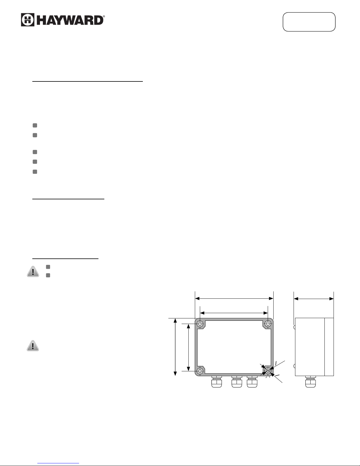
To install device on the wall, pinholes
should be made. Figure 4.1 presents
dimensions of the device and
distances between holes. The back
side of the device has four mounng
holes. This part of the case should be
mounted to a wall by screws.
80 mm
60 mm
110 mm
90 mm
o
o
4.4
8.4
67 mm
Figure 4.1. Device and assembly dimensions
haywardowcontrol.com
REV2-6
Page 7

TLC Series
4.3. CONNECTION METHOD
Due to possible significant interference in industrial installaons appropriate measures
assuring correct operaon of the unit must be applied. To avoid the unit of improper
indicaons keep recommendaons listed below.
Installaon should be conducted by qualified personnel. During installaon all available safety
requirements should be considered. The fier is responsible for execung the installaon according
to this manual, local safety and Federal regulaons.
The unit is not equipped with an internal fuse or power supply circuit breaker. Because of this, an
external me-delay cut-out fuse with a small nominal current value must be used (recommended
bipolar, max. 2A) and a power supply circuitbreaker located near the unit. In the case of using a
monopolar fuse it must be mounted on the phase cable (L).
The power supply network cable diameter must be selected in such a way that in the case of a short
circuit of the cable from the side of the unit the cable shall be protected against destrucon with an
electrical installaon fuse.
Wiring must meet appropriate standards and local regulaons and laws.
In order to secure against accidental short circuit the connecon cables must be terminated with
appropriate insulated cable ps.
Tighten the clamping screws. The recommended ghtening torque is 0.5 Nm.Loose screws can
cause fire or defecve operaon. Over ghtening can lead to damaging the connecons inside the
units and breaking the thread.
In the case of the unit being fied with separable clamps they should be inserted into appropriate
connectors in the unit, even if they are not used for any connecons.
Unused terminals (marked as n.c.) must not be used for connecng any connecng cables (e.g. as
bridges), because this can cause damage to the equipment or electric shock.
If the unit is equipped with housing, covers and sealing to protect against water intrusion, pay
special aenon to their correct ghtening or clamping. In the case of any doubt consider using
addional prevenve measures (covers, roofing, seals, etc.). Carelessly executed assembly can
increase the risk of electric shock
Aer the installaon is completed do not touch the unit's connecons when it is switched on,
because it carries the risk of electrical shock.
haywardowcontrol.com
REV2-7
Page 8
TLC Series
Due to possible significant interference in industrial installaons appropriate measures
assuring correct operaon of the unit must be applied. To avoid the unit of improper indicaons
keep recommendaons listed below. To avoid the unit of improper indicaons keep
recommendaons listed below.
Avoid running signal cables and transmission cables together with power supply cables and cables
controlling inducve loads (e.g. contactors). Such cables should cross at a right angle.
Contactor coils and inducve loads should be equipped with interference protecon systems, e.g.
RC-type.
Use of screened signal cables is recommended. Signal cable screens should be connected to the
earth or ground only at one end of the screened cable.
In the case of magnecally induced interference the use of twisted pair of signal cables is
recommended. Twisted pair (best if shielded) must be used with RS-485 serial transmission
connecons.
In the case of measurement or control signals are longer than 100 Feet or go outside of the building
then addional safety circuits are required.
In the case of interference from the power supply side the use of appropriate interference filters is
recommended. Bear in mind that the connecon between the filter and the unit should be as short
as possible and the metal housing of the filter must be connected to the earth with the largest
possible surface. The cables connected to the filter output must not be run with cables with
interference (e.g. circuits controlling relays or contactors).
Connecon of the power supply, and the measurement and controlling signals should be
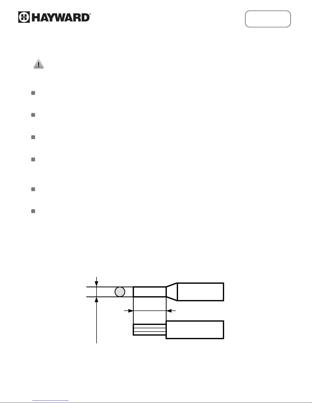
made by screw connectors mounted inside the housing.
0.25"
max. 0.08"
Figure 4.2. Method of cable insulation replacing and cable terminals
haywardowcontrol.com
REV2-8
Page 9

Figure 4.3. Method of connecting cables to the clamping connectors
Wiring Diagram
TLC Series
Source for
Relays output, depends
on the installation
17 16 15 14 13 12 11 10 9 8 7 6 5 4 3 2 1
+
-
Transmitter
Level Sensor
+
J3
-
-
Output
-
External
Display
J4
GND
4-20
4
IN
+
mA
5
+
V
Load no.1
+
Power supply
85.280V
+
SENTINEL 247
4.4. MAINTENANCE
The unit does not have any internal replaceable or adjustable components available to the user. Pay
attention to the ambient temperature in the room where the unit is operating. Excessively high
temperatures can cause faster aging of the internal components and shorten the fault-free time of the unit's
operation. In cases where the unit gets dirty do not clean with solvents. For cleaning use warm water with
small amount of detergent or in the case of more signicant contamination ethyl or isopropyl alcohol.
Using any other agents can cause permanent damage to the housing.
Product marked with this symbol should not be placed in municipal waste.
Please check local regulations for disposal of electronic products.
haywardowcontrol.com
REV2-9
Page 10

5. FRONT PANEL DESCRIPTION
Alarm LED indicator (AL)
TLC Series
Thresholds exceeding
LED indicators (R)
AL R1 R2
Bright Large Display
Infrared Receiver
MENU
Symbols and functions of Push Buttons:
Symbol used in the manual : [ESC/MENU]
ESC
MENU
ENTER
Functions:
• Enter to main menu (press and hold for at least 2 sec.)
• Exit the current screen and enter to previous menu (or measure mode)
• Cancel the changes made in parameter being edited
Symbol used in the manual : [ENTER]
Functions:
• Start to edit the parameter
• Enter into the sub-menu
• Conrmation of changes made in parameter being edited
ESC
ENTER
Programming
Push Buttons
Symbol used in the manual : [^] [v]
Functions:
• Change of the present menu
• Modication of the parameter value
• Change of the display mode
haywardowcontrol.com
REV2-10
Page 11

5.1. TLC Series Quick Start Manual (Step by Step)
PROGAMMING RELAYS
Press ESC/MENU Button for 3 Seconds
ESC
MENU
(Enter Security Code if Required)
Press DOWN Arrow
(Relay 1 Appears on Display)
Press ENTER Button
ENTER
(SETP Appears on Display)
Press ENTER Button
ENTER
(Relay Set-Point Number Appears on Display)
Press UP Or DOWN Arrow To Increase
Or Decrease Number To Desired Setpoint
When Desired Number Appears
ENTER
Press & Hold ENTER (2 Sec)
Press DOWN Arrow To Select Relay Parameters
(ON-OFF, HYSTERISIS, Mode, Time, Unit, Alarm)
TLC Series
(SETP Appears on Display)
Repeat Steps to Set-UP 2nd Relays if Required
PROGRAMMING 4-20mA INPUT
Press ESC/MENU Button for 3 Seconds
ESC
MENU
(Enter Security Code if Required)
Press DOWN Arrow
(inPT Appears on Display)
Press ENTER Button
ENTER
(tyPE Appears on Display)
Press DOWN Arrow (4X)
(Lo C Appears on Display)
Press ENTER Button –(4Ma)
ENTER
(ALL ZERO’s (0000)-This is Standard = 4mA Set-Point)
ESC
Press ESC/MENU Button
MENU
Press DOWN Arrow
(Hi C Will Appear on Display)
Press ENTER Button—(20Ma) ---> This Will be the MAX Valve.
ENTER
(Numbers will Appear-Change Using Up/Down Arrows to Set Desired 20mA Set-Point)
ENTER
Press ENTER—(Hold 3 Sec) SET? Appears Press ENTER Again
Wiring Diagram
Source for
Relays output, depends
on the installation
17 16 15 14 13 12 11 10 9 8 7 6 5 4 3 2 1
+
-
-
-
Transmitter
Level Sensor
+
J4
GND
J3
4-20
Output
mA
External
Display
4
5
+
V
IN
Load no.1
Power supply
85.280V
+
+
ESC
Press ESC/MENU to Return to Main Menu
MENU
Remember 4mA = 0, 20mA = MAX Level
haywardowcontrol.com
-
+
SENTINEL 247
REV2-11
Page 12

TLC Series
6. PRINCIPLE OF OPERATION
After turning the power supply on, device ID and software version are shown on the display, next the
controller will go into the measurement mode.
6.1. MEASUREMENT MODE
In the measure mode, the measurement results, converted over selected characteristic, are displayed on the
LED display. The measurement range equal to the nominal range is called: nominal measurement range, and
the measurement range equal to the extended nominal range is called: permissible measurement range
(Figure 6.1, 6.2).
"Lo r" parameter
"Hi r" parameter
nominal measurement range
4 mA 20 mA
permissible measurement range
Figure 6.1. Definitions of measurement ranges in mode 4-20mA
If the measurement value does not exceed permissible measurement range but displayed value
exceeds range -999 - 9999, the warning "-Ov-" is displayed rather than the calculated value.
In the measurement mode user can check main threshold values. After pressing [^] or [v] button, name of
the threshold (e.g. "rEL1") and the value will be displayed on the display in an alternating mode. If [^] or [v]
is pressed within 5 sec, the next threshold will be displayed, otherwise the device will return to the
measurement mode. If a free access is enabled (see description of "SECu" menu), user can change the value
of particular threshold pressing button [ENTER] (see : PARAMETERS EDITION).
Input type, range of displaying values, characteristic of conversion, decimal point position, and measure
ltering ratio, are user congurable parameters. All accessible parameters can be changed by entering the
menu (see: DEVICE PROGRAMMING). Use the local keyboard or the remote controller to do it. (Note: All
parameters can be remotely changed via RS-485 interface).
Conguration of the device (via menu or RS-485 interface) does not stop the measurements.
haywardowcontrol.com
REV2-12
Page 13

TLC Series
6.2. DETECTION OF THE PEAK VALUES
The TLC Series controller is equipped with a peak detection function. It can detect the peak of the input
signal and display the values. Presets connected with this function are placed in a "HOLd" menu (see
description of "HOLd" menu). The detection of the peak can be done if the measured signal raises and
drops in value at least equal to parameter "PEA". Detected peaks are displayed during the time dened by
parameter "timE". If a new peak is detected while the current one is displayed, this new peak will be
displayed and display time counter will be cleared (Figure 6.3). If no peaks are detected while time "timE"
elapses, device starts to show the current value of input signal once again. If "HdiS"="HOLD" then setting
parameter "timE"=0.0 causes holding peak value until [ESC] button is pressed. If "HdiS"="rEAL" then value
"timE"=0.0 means no holding. Displaying peak value is signalized by ashing most right decimal point.
The relays/LEDs can be controlled depending on the current value of input signal or the peak value (see
"HOLd" menu).
measure
"timE"
"timE"
"PEA"
"PEA"
real measurement result
display value
Figure 6.3. Process of peaks detection
time
6.3. CONTROL OF THE RELAY OUTPUTS
The control of the input (Fluid) (measured signal) is realized via relay outputs. Front panel LEDs named "R"
indicates the state of particular relay output.
If device is not equipped with one or more relay outputs, menus refer to the relays being available,
but apply to LED indicators only. In such case LEDs indicates exceeding of particular thresholds but
no relay will be activated.
Modes of the control can be changed depending on the values of parameters "SEtP", "SEt2", "HYSt",
"modE", "t on", "toFF", " unit" and "AL". Depending on "modE" parameter, relays can be not used or
controlled over one or two thresholds values.
If one threshold is used (Figure 6.4) the relay can be turned on ("modE" = "on") or o ("modE" = "oFF")
when the input signal value is contained in zone A. If two thresholds are used (Figure 6.5) the relay will be
turned on when value of input signal is contained in zone A ("modE" = "in") or zone B ("modE" = "out") and
turned o if the signal is contained in the second one.
haywardowcontrol.com
REV2-13
Page 14

State of
Relay/LED
TLC Series
"SEtP" Parameter
Figure 6.4. One threshold control of the Relay/LED outputs
State of
Relay/LED
zone B
zone B
"SEtP" or "SEt2"
zone A
zone A
Measure
"HYSt" Parameter
Parameter
zone B
Figure 6.5. Two threshold control of the Relay/LED outputs
The relay outputs and LEDs (named R) can be controlled depending on both - the
current value and the peak value (when peak detection is active) of the input signal.
"HYSt" Parameter
haywardowcontrol.com
Measure
REV2-14
Page 15

TLC Series
7. DEVICE PROGRAMMING
The device menu allows user to set all the parameters connected to the operation of measurement input, control
modes, critical situations behaviour, communication via RS-485 and access settings. The meaning of the particular
parameters is described in paragraph MENU DESCRIPTION.
Some of the parameters can be accessed without entering menu (Quick View Mode). After pressing [^] or [v] button,
name of the threshold (e.g.”rEL1”) and the value will be displayed on the display in the alternating mode. If [^] or [v] is
pressed within 5 sec, the next threshold will be displayed, else the device comes back to the measurement mode. If a
free access is enabled (see description of ”SECu” menu), user can change the value of particular threshold pressing
button [ENTER] (see: PARAMETERS EDITION).
If particular parameter has been changed and conrmed in the Quick View Mode, the new value is
displayed in the alternating mode with parameter name within a few seconds. Conrmed changes may
be checked or user can switch viewed parameter by pressing [^] or [v] button.
7.1. PROGRAMMING MENU
To enter main menu (being in the measurement mode) operator must press and hold for at least 2 sec. [ESC/MENU]
button.
If the user password is dened (see parameter “Scod“, menu ”SECU”), the operator will have to enter the correct
password before proceeding to the menu options . The entering of the passwords is similar to the edition of numeric
parameters (see: PARAMETERS EDITION), however presently editing the digit is shown only on the display, other
digits are replaced by “-” sign. After entering of last digit of the password rst menu position will be displayed (if the
password is correct) or warning ”Err” if password is incorrect.
Pay attention when device parameters are being changed. If it is possible, turn o controlled installation.
Functions of the buttons while sub-menu and parameters choice:
Selection of sub-menu or parameter for editing. Name of selected item
(submenu or parameter) is displayed.
Operation of [ENTER] button depends on present menu position:
• if the name of some sub-menu is displayed - enter this sub-menu; name of the rst
ENTER
ESC
MENU
After about 1 min. of inactivity the device will exit the menu mode and return to the
measurement mode.
parameter (or next level sub-menu) is displayed,
• if the name of some parameter is displayed - enter the edition of this parameter;
present value of the parameter is displayed,
[ESC/MENU] button allows the user to exit present menu level and goes to
upper level menu (or measurement mode).
haywardowcontrol.com
REV2-15
Page 16

TLC Series
7.2. PARAMETERS EDITION
To start edition of any parameter, user should select name of desired one using [^] [v] buttons and then press
[ENTER].
7.2.1. Numeric parameters (digit change mode)
Numerical parameters are displayed as decimal numbers. The mode of the new value entered depends on chosen edit
method ( see parameter "Edit”).
In mode “by digit” ("Edit”=”dig”) pressing one of the keys [^] or [v] causes change of current position (ashing digit) or
the sign (+/-). Short pressing of the [ENTER] button causes change of the position (digit).
Press [ENTER] for at least 2 seconds to accept the changes, after that question ”SEt?” is displayed, and user must
conrm (or cancel) the changes. To conrm changes (and store it in EEPROM) press [ENTER] button shortly after ”SEt?”
is displayed. To cancel the changes press [ESC] button shortly after ”SEt?” is displayed. After that device returns to the
menu.
7.2.2. Numeric parameters (slide change mode)
In “slide change” mode ("Edit”=”Slid”), buttons [^] and [v] has dierent functions. To increase edited value press (or
press and hold) [^] button only, the increasing becomes faster as long as button [^] is pressed. To slow down the
button [v] can be used. If [v] is pressed shortly (and button [^] is still pressed), increasing will slow down for a moment
only, if [v] is pressed and held while button [^] is still pressed the quick digit change will be kept on lower speed.
To decrease edited value press (or press and hold ) [v] button only. The decreasing becomes faster as long as button
[v] is pressed. To slow down the decrease, button [^] can be used. If [^] is pressed shortly (and button [v] is still
pressed), decreasing slow down for a moment only, if [^] is pressed and held while button [v] is still pressed the Speed
will slow down and will be kept on lower speed.
Press [ENTER] at least 2 seconds to accept the changes, after that question ”Set?” is displayed, the user must conrm
(or cancel) the changes. To conrm the changes (and store them in EEPROM) press the [ENTER] button shortly after
”SEt?” is displayed. To cancel the changes press [ESC] button shortly after ”SEt?” is displayed. After that device returns
to the menu.
7.2.3. Switch parameters (“LIST” type)
Switch parameters can be described as a set of values (a list) out of which only one of the options available on the list
can be selected for the given parameter. Options of switching parameter are selected using [^], [v] keys. Short (Quick)
pressing of [ENTER] results in the display the user to acknowledge the question (”SEt?”). If key [ENTER] is pressed
again, the changes are accepted, stored in EEPROM end the edition process nished. Pressing the key [ESC] after ”SEt?”
causes cancelling of changes made and display returns to the main menu.
Functions of buttons when editing numeric and switching parameters:
While editing numeric parameter:
• Change of current (ashing) digit
• Slide change of value (acceleration, deceleration, direction change)
While editing switch parameter - selection of switch parameter.
haywardowcontrol.com
REV2-16
Page 17

ENTER
TLC Series
If numerical parameter is being edited, a short quick pressing of [ENTER] button will
change edited position. A long press of [ENTER] button (at lest 2 sec.) the display to
request
value is correct. If switch parameter is being edited, a short press of [ENTER] button
causes the display a ”SEt?” conrmation. When [ENTER] button is pressed again (while
”SEt?” is displayed) the new value of the parameter is stored in EEPROM memory.
”SEt?” conrm, which allow user to make sure the change of the parameter
ESC
MENU
Pressing this button the operator can cancel the changes done up to now (if they
were not approved by [ENTER] button after the ”SEt?” request) and will return to
the main menu.
7.3. MENU DESCRIPTION
Password checking. If the password is dierent from "0000", then the number
(password must be entered to enter main menu) follows the entering of password. If
“- - - -”
entered password is correct then rst menu position will be displayed otherwise the
warning "Err", and unit returns to measurement mode.
Due to problem with direct displaying of “m” and “K” letters, they are exchanged with
special signs “ “ for “m” and “ “ for "K" respectively. However, the user manual letters "m" and
"K" are used to make it more readable (example: “modE”, “ tc K”).
7.3.1. “rEL1” menu
This menu allows conguring the operation mode of relays and LEDs marked "R” (e.g. "R1”).
If there are few relay outputs available, then every output has its own conguration menu (e.g. menu "rEL2”
for relay (LED) "R2”). Principle of the relays operation is described in paragraph CONTROL OF THE RELAY OUTPUTS.
•
The relay outputs and LEDs (named R) can be controlled depend on both – the current value and
the peak value (when peak detection is active) of the input signal.
First threshold of the relay (range -999 - 9999). Negative values can be input by
"SEtP"
selecting a “-” sign on rst digit (to change value use [^] and [v] buttons).
Threshold is the median value of relay hysteresis.
haywardowcontrol.com
REV2-17
Page 18

"SEt2"
"HYSt"
Presented parameters should be set to ensure that ”SEtP” + ” H Y S t ”, ”SEt2” + ”HYSt”, ”SEtP” ”HYSt” or ”SEt2” - ”HYSt” does not exceed the measure range. Additionally, in the two
threshold mode (“modE”= "in” or "out”), the hysteresis for both thresholds must not overlap one
another (in other case relay will not change state).
TLC Series
Second threshold of the relay (range -999 - 9999). Negative values can be input by
selecting a “-” sign on rst digit (to change value use [^] and [v] buttons). This
threshold is accessible when ”modE” parameter is set to "in” o r " out” value.
Threshold is the median value of relay hysteresis.
Hysteresis of relay (range 0 - 999). Full hysteresis of the relay is equal to 2x “HYSt”
parameter. The relay state can change when an input signal is out of threshold
hysteresis to threshold+hysteresis zone.
"modE" - relay operation mode:
"noAC"
"on"
"oFF"
"in"
"out"
The relay is not active (permanently turned o)
One threshold mode - the relay is turned ON when input signal exceeds the SEtP +
HYSt value, and is turned o when the input signal becomes lower than SEtP – HYSt,
One threshold mode - the relay is turned OFF when input signal exceeds SEtP +
HYSt value, and is turned on when the input signal becomes lower than SEtP – HYSt,
Two threshold mode - the relay is turned ON when the input signal is greater than
“lower threshold + HYSt” and below than “bigger threshold HYSt”, and turned o
when the input signal is contained within the second zone. The hanger threshold
equals the hanger one of “SEtP” and “SEt2” thresholds, the smaller threshold”
means the smaller one of “SEtP” and “SEt2” thresholds.
Two threshold mode - relay is turned ON when the input value is greater than
“bigger threshold + HYSt” and lower than “smaller threshold – HYSt”, and turns
on when the input signal is contained in the second zone. The hanger threshold
means hanger one of “SEtP” and “SEt2” thresholds, the Smaller threshold” means
smaller one of “SEtP” and “SEt2” thresholds.
haywardowcontrol.com
REV2-18
Page 19

TLC Series
"modb"
• LEDs lights up when relays are closed, independently of relays' mode.
• When the power supply fails, the unit does not store relays state selected by RS- 485 interface.
"t on"
"toFF"
The relay is controlled via RS-485 interface, independently on the input signal.
Turn on the delay time- the relay is turned on with delay equal “t on” if the input
value exceeds the appropriate border value (dened with threshold and
hysteresis), “t on” time. “t on” range 0 - 99.9, dened with 0.1 sec. resolution. Unit of
this parameter is set by “unit” parameter.
Turn o delay time- the relay is turned o with delay equal “toFF” if the input value
exceeds appropriate border value (dened with threshold and hysteresis), “toFF”
time. “toFF” range 0 - 99.9, dened with 0.1 sec. resolution. Unit of this parameter is
set by “unit” parameter.
If time when the input signal exceeds some border value and is shorter than the “t on” or
“toFF” time, the relay does not change its state (see paragraph: CONTROL OF THE RELAY
OUTPUTS).
"unit"
"AL"
Unit of time for “t on” i “ toFF” parameters. The unit be set to one of two values:
"min"
"SEC"
This parameter denes the relay reaction when some critical situations occurs:
"noCH"
"on"
"oFF"
If parameter “modE” is set to “on” , “oFF”, “ in” or “Out” the “critical situation” means that the
allowable measurement range is exceeded. If parameter "modE" is set to "modb", the
"critical situation" means the communication delay (when no data is received) is longer than
"mbtO" parameter (see description: "rS" menu).
minutes
seconds
relay does change state,
relay will be turned on,
relay will be turned o.
haywardowcontrol.com
REV2-19
Page 20

7.3.2. “inPt” menu
This menu presets the measurement input:
Type of the input / sensor. This parameter can be set to values:
TLC Series
"tYPE"
"CHAr"
"USEr"
"tn v"
"0-20", " 4-20" - current inputs.
Displayed values are dened by parameters "Lo C","Hi C" (or by user dened
characteristic points) and parameter "Pnt".
This option presets the type of the conversion characteristic, and can be set to:
"Lin"
"Sqr"
"Sqrt"
When one of those characteristics is chosen display range is dened by "Lo C" and "Hi C".
User dened characteristic. Maximum length 20 points. Every point is dened by user.
Adding, Editing and Deleting of points is done by options "AddP", "EdtP", " dELP" ("InPt"
menu) respectively.
Volume characteristics of a cylindrical tank in the vertical position, determined by
parameters: "t h1", " t h2", "t h3", " t d", " t Sn", "t Sh" in "InPt" menu (see below for details
of the parameters),
linear
square
square root
Volume characteristics of a cylindrical tank in the horizontal position, determined by
"n h"
If user dened characteristic is selected, and if number of dened points is lower than 2 then
warning "Errc" is displayed in measurement mode.
The process of displayed result calculation is described in details in DISPLAY VALUES CALCULATION
paragraph.
"FiLt"
parameters: "t h1", " t h2", "t h3", " t d", " t Sn", "t Sh" in "InPt" menu (see below for details
of the parameters).
This parameter sets ltration rate. It can be set to values from 0 (no ltration) to 5
(strongest ltration - time window about 2 sec).
haywardowcontrol.com
REV2-20
Page 21

"Pnt"
"Lo C"
"Hi.C"
TLC Series
Decimal point position. It can be set to one of:
"0", " 0.0", " 0.00", "0.000"
Decimal point position is changed by [^], [v] buttons.
These parameters describe the values displayed for minimum and maximum input
current. For example, if input type is set to 4-20 mA "Lo C" parameter denes the value
displayed when input current is equal to 4 mA, and "Hi C" parameter denes the value
displayed for 20 mA of the input current highest value. Available range for these
parameters: -999 - 9999. Negative values can be set by entering '-' sign on the rst
position (by use of [^], [v] buttons).
"AddP", " dELP" and "EdtP" options are available only if the user dened characteristic is used (it
means when parameter "CHAr" = "USEr").
"Lo r"
"Hi r"
"Lo r" = 75,0% (3 mA)
min
0 1 4 20
display
message "-Lo-"
These parameters dene the expansion of nominal range in percent. They determine
the permissible range of input signal (Figure 7.3). The permissible range allow user to
exceed the nominal range of input signal. If the input value is contained within the
permissible range correct result is displayed. If input signal exceeds this range (dened
by "Lo r" and "Hi r"), "-Lo-" or "-Hi-" warning is displayed depends on the input signal
value.
"Hi r" = 5,0 % (1 mA)
nominal measurement range (4-20mA)
permissible measurement range
measurement result is displayed
regardless on nominal range exceeding
Figure 7.3 Example of defining a permissible range of input signal -
"Lo r" and "Hi r" parameters ("4-20" mode)
21 22
display
message "-Hi-"
max
[mA]
The “Lo r” parameter is important if input is set to “4-20”, “1-5” or “2-10” mode only, and determines lower
border of the permissible range.
haywardowcontrol.com
REV2-21
Page 22

TLC Series
For example if input is set to “4-20” mode, the lower border is calculated to expression: Imin = 4 mA
- 4 mA × “Lo r” %. The “Lo r” value can be set from 0 to 99.9%. Parameter “Hi r” determines the upper
border of the permissible range accordingly to the expression (for all modes). For example if input is
set to “4-20” mode, then upper border is calculated due to expression: Imax = 20 mA + 20 mA × “Hi
r” %. The value of “Hi r” can be set from 0 to 19.9%
If the measurement value do not exceeds permissible measurement range but displayed
value exceeds range -999 - 9999, the warning ”-Ov-” is displayed rather than the calculated
result.
7.3.3. ”bri” parameter
This parameter allows user to set bright of the LED display, bright can be set to conventional values from
1 to 8.
7.3.4. ”HOLd” menu
This menu contains parameters connected with peak detection function. See also full description of the
peak detection function in paragraph: DETECTION OF THE PEAK VALUES “mo
changes of the input signal, can be set to values:
”norm”
”inv”
peaks, peak and next drop of the input signal of value equal at least “PEA”,
drops, drop and next peak of the input signal of value equal at least “PEA”
”PEA”
maximum time to display of the peak (drop) value, the value can be set from 0.0 to
“timE”
19.9 sec, with a 0.1 sec. resolution. If "HdiS”=”HOLD” then sett parameter
"timE"=0.0 will peak value until [ESC] button is pressed. If "HdiS”=”rEAL” then the
value "timE"=0.0 will not be hold.
dE” - the type of detected
“HdiS”
type of displayed values
haywardowcontrol.com
REV2-22
Page 23

Press
Press
7.4. MENU STRUCTURE - SETTING RELAYS
Measurement mode
ESC
Press and hold at least 5 seconds
0
MENU
4-digit user password Required (if it is different from "0000")
ENTER
rEL1
ESC
MENU
ESC
MENU
ENTER
SEtP
SEt2
TLC Series
ENTER
Parameter
edition
ESC
ENTER
MENU
Press
Press
ESC
MENU
ESC
MENU
rEL2
inPt
ENTER
ESC
MENU
Options similar
to "rEL1" menu
ENTER
ESC
MENU
tYPE
CHAr
FiLt
Pnt
Lo C
Hi C
t h1
t h2
ENTER
ENTER
ESC
MENU
HYSt
ESC
MENU
modE
t on
toFF
Parameter
edition
unit
AL
Linear
4 mA (No NEMA to Enter #)
20 mA (Max Value)
Press
ESC
MENU
bri
ENTER
ENTER
ESC
MENU
Parameter
Edition
Increase LED Brightness
t h3
t d
t Sn
t Sh
AddP
dELP
EdtP
Lo r
Hi r
haywardowcontrol.com
REV2-23
Page 24

TLC Series
8. THE ALARM LED
The ALARM LED (AL) is turned on when input signal is out of the permissible input range. See parameters: “tyPE”, “ Lo
r” and “Hi r” in paragraph "InPt” menu.
9. OVER-CURRENT PROTECTION
The current input of the device is equipped with over-current protection circuit. This circuit protects the standard
resistor against damage. Maximum input current is set to 40mA (typical). When temperature of the standard resistor
falls, the protection circuit will turn on automatically, and the device will measure the input current again. Due to
thermal phenomenon in the standard resistor, precision of the measurement may be lower until the standard resistor
temperature falls to the environment temperature.
USA: 1.888.429.4635 • Fax: 1.888.778.8410 • One Hayward Industrial Drive • Clemmons, NC 27012 • Email: how@haywardnet.com
Canada: 1.888.238.7665 • Fax: 1.905.829.3636 • 2880 Plymouth Drive • Oakville, ON L6H 5R4 • Email: howcanada@haywardnet.com
Contact Hayward Flow Control with questions:
haywardowcontrol.com
REV2-24
 Loading...