

Hayward Swim Pro Owner's Manual
IS0240TC Rev Oz
g
®
Swim Pro
OWNER’S GUIDE | GUIDE DE L’UTILISATEUR | GUÌA DEL USUARIO
HAYWARD SAND FILTERS FILTRES A SABLE HAYWARD FILTROS DE ARENA
Basic safety precautions should always be followed, including the following: Failure to follow instructions can cause severe injury
and/or death.
IMPORTANT SAFETY INSTRUCTIONS
This is the safety-alert symbol. When you see this symbol on your equipment or in this manual, look for one of the following
signal words and be alert to the potential for personal injury.
WARNING warns about hazards that could cause serious personal injury, death or major property damage and if ignored
presents a potential hazard.
CAUTION warns about hazards that will or can cause minor or moderate personal injury and/or property damage and if
i
nored presents a potential hazard. It can also make consumers aware of actions that are unpredictable and unsafe.
Use only High Rate Sand No. 20 Silica Sand (.45mm - .55mm)
WARD POOL EUROPE - Parc Industriel de la Plaine de l’ain - Allée des Chênes - 01150 Saint Vulbas - France
HAY
HAYWARD CANADA 2880 Plymouth Drive, Oakville Ontario, Canada L6H 5R4
HAYWARD AUSTRALIA - PO Box 4384, Dandenong South, VIC, 3175, AU
HAYWARD/IMG INTERNATIONAL Marketing Group, 2875 Pomona Blvd. Pomona, CA 91768, USA
Models VL210T, VT240T, VT270T
WARNING - Read and follow all instructions in this owner’s manual and on the equipment.
Failure to follow instructions can cause severe injury and/or death.
WARNING – Suction Entrapment Hazard.
Suction in suction outlets and/or suction outlet covers which are, damaged, broken, cracked, missing, or unsecured can cause
severe injury and/or death due to the following entrapment hazards:
Hair Entrapment- Hair can become entangled in suction outlet cover.
Limb Entrapment- A limb inserted into an opening of a suction outlet sump or suction outlet cover that is damaged, broken,
cracked, missing, or not securely attached can result in a mechanical bind or swelling of the limb.
Body Suction Entrapment- A negative pressure applied to a large portion of the body or limbs can result in an entrapment.
Evisceration/ Disembowelment - A negative pressure applied directly to the intestines through an unprotected suction outlet
sump or suction outlet cover which is, damaged, broken, cracked, missing, or unsecured can result in evisceration/
disembowelment.
Mechanical Entrapment- There is potential for jewelry, swimsuit, hair decorations, finger, toe or knuckle to be caught in an
opening of a suction outlet cover resulting in mechanical entrapment.
WARNING - To Reduce the risk of Entrapment Hazards:
o When outlets are small enough to be blocked by a person, a minimum of two functioning suction outlets per pump must
be installed. Suction outlets in the same plane (i.e. floor or wall), must be installed a minimum of three feet (3’) [1 meter]
apart, as measured from near point to near point.
o Dual suction fittings shall be placed in such locations and distances to avoid “dual blockage” by a user.
o Dual suction fittings shall not be located on seating areas or on the backrest for such seating areas.
o The maximum system flow rate shall not exceed the flow rating of as listed on Table 1.
o Never use Pool or Spa if any suction outlet component is damaged, broken, cracked, missing, or not securely attached.
o Replace damaged, broken, cracked, missing, or not securely attached suction outlet components immediately.
o In addition two or more suction outlets per pump installed in accordance with latest ASME, APSP Standards and CPSC
guidelines, follow all National, State, and Local codes applicable.
o Installation of a vacuum release or vent system, which relieves entrapping suction, is recommended.
WARNING – Failure to remove pressure test plugs and/or plugs used in winterization of the pool/spa
from the suction outlets can result in an increase potential for suction entrapment as described above.
WARNING – Failure to keep suction outlet components clear of debris, such as leaves, dirt, hair, paper
and other material can result in an increase potential for suction entrapment as described above.
WARNING – Suction outlet components have a finite life, the cover/grate should be inspected frequently
and replaced at least every ten years or if found to be damaged, broken, cracked, missing, or not securely
attached.
CAUTION – Components such as the filtration system, pumps and heater must be positioned so as to
prevent their being used as means of access to the pool by young children.
WARNING – Never operate or test the circulation system at more than 50 PSI.
WARNING – Never change the filter control valve position while the pump is running.
WARNING – To reduce risk of injury, do not permit children to use or climb on this product. Closely supervise children at
all times. Components such as the filtration system, pumps, and heaters must be positioned to prevent children from using them
as a means of access to the pool.
WARNING – Hazardous Pressure. Pool and spa water circulation systems operate under hazardous pressure
during start up, normal operation, and after pump shut off. Stand clear of circulation system equipment during pump start
up. Failure to follow safety and operation instructions could result in violent separation of the pump housing and cover,
and/or filter housing and clamp due to pressure in the system, which could cause property damage, severe personal injury,
or death. Before servicing pool and spa water circulation system, all system and pump controls must be in off position and
filter manual air relief valve must be in open position. Before starting system pump, all system valves must be set in a
position to allow system water to return back to the pool. Do not change filter control valve position while system pump is
running. Before starting system pump, fully open filter manual air relief valve. Do not close filter manual air relief valve until
a steady stream of water (not air or air and water) is discharged.
WARNING – Separation Hazard. Failure to follow safety and operation instructions could result in violent separation
of pump and/or filter components. Strainer cover must be properly secured to pump housing with strainer cover lock ring.
Before servicing pool and spa circulation system, filters manual air relief valve must be in open position. Do not operate pool
and spa circulation system if a system component is not assembled properly, damaged, or missing. Do not operate pool and
spa circulation system unless filter manual air relief valve body is in locked position in filter upper body.
USE ONLY HAYWARD GENUINE REPLACEMENT PARTS
Page 2 of 15 Swim Pro® by HAYWARD® Sand Filter
IS0240TC REV OZ
WARNING – Risk of Electric Shock. All electrical wiring MUST be in conformance with applicable local codes,
regulations, and the National Electric Code (NEC). Hazardous voltage can shock, burn, and cause death or serious property
damage. To reduce the risk of electric shock, do NOT use an extension cord to connect unit to electric supply. Provide a properly
located electrical receptacle. Before working on any electrical equipment, turn off power supply to the equipment.
WARNING – To reduce the risk of electric shock replace damaged wiring immediately. Locate conduit to prevent abuse
from lawn mowers, hedge trimmers and other equipment.
WARNING – Electrical ground all electrical equipment before connecting to electrical power supply. Failure to ground all
electrical equipment can cause serious or fatal electrical shock hazard.
WARNING – Do NOT ground to a gas supply line.
WARNING – To avoid dangerous or fatal electrical shock, turn OFF power to all electrical equipment before working on
electrical connections.
WARNING – Failure to bond all electrical equipment to pool structure will increase risk for electrocution and could result in
injury or death. To reduce the risk of electric shock, see installation instructions and consult a professional electrician on how to
bond all electrical equipment. Also, contact a licensed electrician for information on local electrical codes for bonding
requirements.
Notes to electrician: Use a solid copper conductor, size 8 or larger. Run a continuous wire from external bonding lug to
reinforcing rod or mesh. Connect a No. 8 AWG (8.4 mm
pressure wire connector provided on the electrical equipment and to all metal parts of swimming pool, spa, or hot tub, and metal
piping (except gas piping), and conduit within 5 ft. (1.5 m) of inside walls of swimming pool, spa, or hot tub.
IMPORTANT - Reference NEC codes for all wiring standards including, but not limited to, grounding, bonding and other general
wiring procedures.
2
) [No. 6 AWG (13.3 mm2) for Canada] solid copper bonding wire to the
WARNING – Risk of Electric Shock. Connect only to a branch circuit protected by a ground-fault circuit-interrupter (GFCI).
Contact a qualified electrician if you cannot verify that the circuit is protected by a GFCI.
WARNING – Risk of Electric Shock . The electrical equipment must be connected only to a supply circuit that is protected
by a ground-fault circuit-interrupter (GFCI). Such a GFCI should be provided by the installer and should be tested on a routine
basis. To test the GFCI, push the test button. The GFCI should interrupt power. Push reset button. Power should be restored. If
the GFCI fails to operate in this manner, the GFCI is defective. If the GFCI interrupts power to the electrical equipment without the
test button being pushed, a ground current is flowing, indicating the possibility of an electrical shock. Do not use this electrical
equipment. Disconnect the electrical equipment and have the problem corrected by a qualified service representative before
using.
CAUTION – This pump is intended for use with permanently-installed pools and may be used with hot tubs and spas if so
marked. Do not use with storable pools. A permanently-installed pool is constructed in or on the ground or in a building such
that it cannot be readily disassembled for storage. A storable pool is constructed so that it is capable of being readily
disassembled for storage and reassembled to its original integrity.
SAVE THESE INSTRUCTIONS
To original purchasers of this equipment, Hayward Pool Products, Inc. warrants its filtersto be free from defects in materials and workmanship for a period of
HAYWARD® Pool Products Limited Warranty
ONE (1) year from the date of purchase, when used in single family residential applications.
The limited warranty excludes damage from freezing, negligence, improper installation, improper use or care or any Acts of God. Parts that fail or become
defective during the warranty period shall be repaired or replaced, at our option, within 90 days of the receipt of defective product, barring unforeseen delays,
without charge.
Proof of purchase is required for warranty service. In the event proof of purchase is not available, the manufacturing date of the product will be the sole
determination of the purchase date.
To obtain warranty service, please co
Authorised Service Center please visit us at www.hayward-pool.com.au.
Hayward shall not be responsible for cartage, removal, repair or installation labor or any other such costs incurred in obtaining warranty replacements or
repair.
Fo
r International Warranty-Contact your product supplier, or write to sales@hayward-pool.com.au.
The Hayward Pool products warranty does not apply to components manufactured by others. For such products, the warranty established by the respective
manufacturer will apply.
The express limited warranty above constitutes the entire warranty of Hayward Pool Products with respect to its’ pool products and is in lieu of all other
warranties expressed or implied, including warranties of merchantability or fitness for a particular purpose. In no event shall Hayward Pool products be
responsible for any consequential, special or incidental damages of any nature.
Some states do not allow a limitation on how long an implied warranty lasts, or the exclusion of incidental or consequential damages, so the above limitation
may not apply to you. This warranty gives you specific legal rights, and you may also have other rights, which vary from state to state.
*Supersedes all previous publications.
Page 3 of 15 Swim Pro® by HAYWARD® Sand Filter
ntact the place of purchase or the nearest Hayward Authorised Service Center. For assistance on your nearest Hayward
USE ONLY HAYWARD GENUINE REPLACEMENT PARTS
Hayward Pool Products (
PO Box 4384, Dandenong South, VIC, 3175
Australia) Pty Ltd
IS0240TC REV OZ
OPERATION
Your filtration system uses filtration sand designed to trap impurities from the pool water. The sand in the tank acts as the
filtration media. The pump draws in unfiltered pool water, which contains impurities in suspension and feeds it through the
multi-port control valve to the top of the sand in the filter. When the water flows through the sand, the impurities are trapped
and the filtered water then returns to the pool.
INSTALLATION
1. Locating the filter: Find a clean, level spot. The top of the filter must be no more than 2 m abov
2. Ass
3. Filling the filter. The sand is put in through the opening in the top of the filter.
a. P
b. Half-fill the filter with water
c. Remove the s
4.
a.
b.
c.
5.
6.
7.
(see figure 1 spare parts list) .
the water level. P
reach. This wi
embling the pump: Assemble the pump and its mount near the filter as indi
manufacturer’s instructions.
lace the underdrain assembly (6) on the bottom of the tank and cover the op
tub
e with the sand shield (5) provided for this purpose. This prevents sand
Make sure tha
Check that the underdrain tube (6) remai
reach the middle of the filter.
mbling the valve: Place the valve (1), with its gasket (3), on the top of the filt
Asse
Make sure that the “PUMP” outlet of the va
Then attach with the clamp (4).
Remove the black plastic screw on the side of the valve
it with the pre
Connect the “PUMP” outlet (P) of
pump as indicated by the manufacturer’s instructions
Con
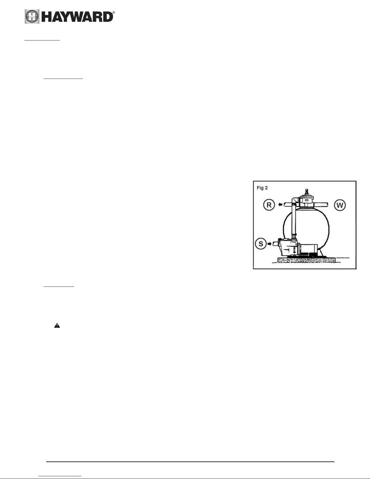
necting the valve: Then connect the pipes from th
fig. 2) and from the skim
strainer side. Connect the discharge pipes to the valve port marked
“RETURN” (R), and the drain conne
“WASTE” (W)
Make th
fro
To avo
all connections are secure.
e electrical connections: Foll
m the manu
id leaks: Make sure that the drain plug (7) is in pl
lace the filter so that the piping, the valve (1), and
ll make servic
t the drain plug (7) is in plac
nd shield (5).
a
ssure gauge (2). Screw in by
facturer.
ing and winterizing easier.
e.
, then pour in the required quantity of sand (see Table II
ns straight. Th
lve is toward the pump.
hand without forcing.
the valve to the top outlet of the
mers (S) to the front port of the pump, on the
ction to the valve port marked
ow the pump instructions
e surface of the sand should be leveled and
and replace
e pool (see
ace and that
the drain plug (7) are easy to
e
cated by the
ening in the top of the
from entering the tube.
-on last page).
er.
START UP:
IMPORTANT: ALWAYS STOP THE PUMP BEFORE CHANGING POSITIONS OF THE MULTIPORT VALVE.
1. Check that all connections are secure and that the filter contains the correct amount of sand.
2. Set the valve to “BACKWASH”. Always lower the handle before turning.
3. Start the pump as indica
the circuit.
WARNING: All suction and discharge valves must be open when the pump is started.
Once the water flows smoothly, let the pump run for
recommended to eliminate impurities from the filtration sand.
4. Stop the pump and set the
clear in the valve sight glass (about a minute).
5. Stop the pump and set the
and outlet valves for the desired water flow.
6. Note the pres
filter operates, impurities ar
initial pressur
1: During initial clean-up of the pool water, it may be necessary to backwash the filter frequently due to
Note
the possibility the new water contained a large quantity of impurities.
Note 2: Clean the pump strainer basket and skimmers regularly to ensure trouble free operation of your
filtration system.
sure reading at startup and the position of the needle on the pressu
e (clean filter) by 0.5 bars, the filter needs be backwash
ted by the manufacturer’s instructions. Check that water flows normally
at least another 2 minutes. This backwash is
valve to “RINSE”. Restart the pump and let it run until the water be
valve to “FILTER”. Restart the pump and filtering starts. Adjust
re gauge. As the
e retained and the pressure increases in the tank. When it exceeds
ed.
comes
the inlet
USE ONLY HAYWARD GENUINE REPLACEMENT PARTS
in
the
Page 4 of 15 Swim Pro® by HAYWARD® Sand Filter
IS0240TC REV OZ

FUNCTIONS OF VALVE AND FILTER
FILTER
Set the valve to “Filter” for normal filtration (6 to 8 hour
s a day).
BACKWASH
When filter pressure gauge rises 8-10 PSI (0.5 bars) above startup (clean pressure)
Run the pump until the water in the sight glass is clear. Stop the pump about 2 minutes later and set the valve
to “Rinse”.
RINSE
With the valve set to “Rinse”, run the pump for about one minute. This removes the dirty backwash water
from the valve to a drain, not the pool. Stop the pump, set back to “Filter”, and restart.
WASTE
The water is discharged directly to the drain without going through the filter: to lower the pool water level
and when using the vacuum it ports dirty water to the drain.
RECIRCULATE
The water bypasses the filter, for rapid dis
persion of chemicals or for massive chlorination.
CLOSED
Cuts off circulation between the filter and the pump.
NEVER USE THE CLOSED POSITION WITH THE PUMP RUNNING.
WINTERIZING
1. Completely drain tank by unscrewing drain cap at base of filter tank. Leave cap off
during winter.
2. Rotate and leave the valve handle in the “WINTER” position.
3. Drain and winterize the pump according to pump instructions.
LIST OF POSSIBLE PROBLEMS
THE FLOW FALLS OFF
AND/OR THE PRESSURE
GAUGE READING EXCEEDS
THE INITIAL PRESSURE BY
10 PSI ( 0,7 bars or
kg/cm2 ).
1. Check and empty the
skimmer and pump strainer
baskets.
2. Check that there is nothing
pinching or plugging the
water intake and return
lines.
3. Check that there is no leak
in the water intake line
(shown up by air bubbles in
the water returned to the
pool).
4. Back
wash the filt
er.
IT BECOMES NECESSARY
TO CLEAN MORE AND
MORE OFTEN
1. Che
ck the pool for algae. If
necessary add disinfectant.
2. Check that the disinfectant
level and pH are correct
(adjust if necessary).
3. Check that the surface of
the sand has not solidified
or become clogged (if so,
remove 2 or 3 cm of sand).
THE POOL WATER DOES
NOT BECOME CLEAR
1. Check the disinfectant
level, pH, and total
alkalinity and adjust if
necessary.
2. Make sure that the
filtration flow is correct.
3. Run the filter longer.
4. Make sure that the valve
is set to ” Filter”.
5. Make sure that your
installation is properly
ed.
connect
USE ONLY HAYWARD GENUINE REPLACEMENT PARTS
Page 5 of 15 Swim Pro® by HAYWARD® Sand Filter
IS0240TC REV OZ
 Loading...