

Hayward Super Star Clear C2000, Super Star Clear C3000, Super Star Clear C4000, Super Star Clear C5000 Owner's Manual
PUMP SELECTION AND LOCATION
To power your filter, select a continuous duty pump designed
for swimming pool or spa service.
It is important to first determine where your pump and filter will
be located. If above the water line, a self-priming pump must
be used. Self-priming pumps (
such as Hayward Super Pump®,
Super II™ or Max-Flo™
) have the ability to lift water from a
lower level and prime automatically.
Select a pump with an average output range suitable for the filter's
capacity. Other considerations are operation of hydrotherapy
fittings, automatic cleaners, etc. Your dealer will help you
select the proper size pump for your system.
FILTER LOCATION
Since plumbing fittings offer a resistance to water flow,
position the filter as close to the swimming pool as practical.
Keep the number of fittings to a minimum. Select a
well-drained area, one that will not flood when it rains.
The filter should be placed on a
level
concrete slab, very
firm ground, or equivalent, as recommended by your pool
dealer. Allow a top clearance for cartridge removal of 18”
(457 mm) for C2000, C3000 and C4000, 22” (559 mm) for
C5000. Be sure filter, pump, drain and pressure gauge are
accessible for convenient operation.
Position filter so the tank can drain by gravity.
If practical, place pump and filter in the shade to shield it
from continuous, direct heat from the sun.
PLUMBING
Use 1-1/2” or 2” piping. Connections are 1-1/2” socket
(solvent weld) or 2” male slip. We suggest unions be
provided for easy servicing.
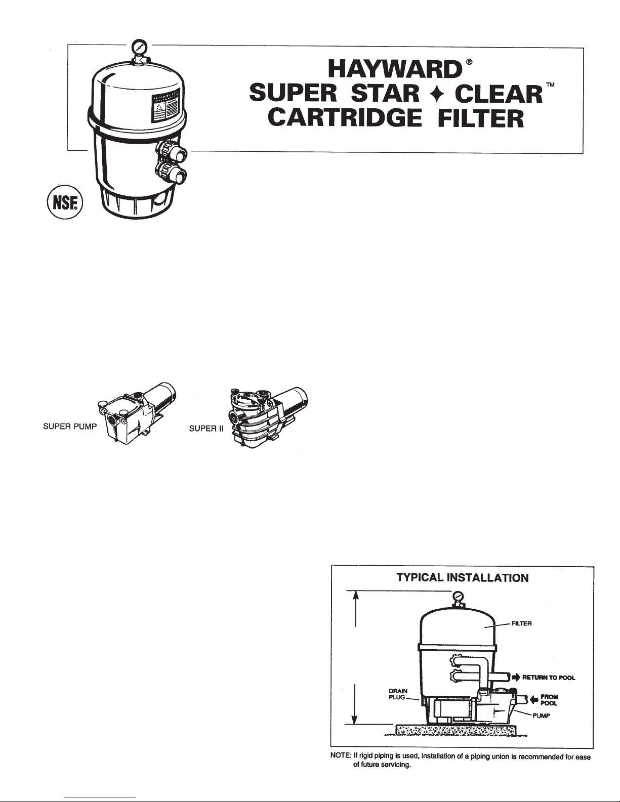
Refer to the diagram for typical installation. Ball valves are
recommended where needed. While all systems vary, the
main consideration is to provide the desired control of
water flow from the pool to the pump and filter and back to
the pool. When the filter is located below the water level,
provide valves to prevent back flow of water to the filter
during cleaning and routine servicing.
Connect the pool suction plumbing between the skimmer,
pool outlet, etc., and the pump.
Install the pool return plumbing.
If pressure gauge is not installed, apply Teflon tape to the
gauge threads, and
carefully
screw the gauge into the
gauge adapter assembly.
A filter drain plug is furnished with each filter and is all that
is needed for complete filter draining. A manual air vent
valve is furnished to aid in bleeding off unwanted air when
starting the filter. The auto air relief provides air removal
during operation.
All electrical connections should be made in accordance
with local codes.
Check for joint leaks before operating.
Refer to pump instruction booklet for pump information.
NOTE: ANSI/NSPI-4 Article V, standard for above-ground and
on-ground pools, advises that components such as the
filtration system, pumps and heater be positioned so as to
prevent their being used as a means of access to the pool by
young children.
BEFORE STARTING THE FILTER
Superchlorinate the pool water by adding unstabilized granular
or liquid chlorine. Stabilized forms of chlorine are recommended
for normal daily use after the initial clean up of the water.
Follow chemical manufacturer’s recommendations for
superchlorination and daily use.
ISC2000-98
1.
2.
3.
4.
1.
2.
3.
4.
5.
6.
7.
8.
9.
OWNER’S GUIDE
MODELS C2000, C3000, C4000, C5000
Hayward Super Star-Clear filters are high performance swimming pool filters with filtration ratings to 9000
gallons (34 KL) per hour. Manufactured from durable, corrosion-proof materials, they are designed for
continuous or intermittent operation, for installation above or below the pool water line, for fresh or salt water
swimming pools or spas. Star-Clear filters utilize multiple reusable, reinforced polyester filter cartridge
elements to provide a high degree of water clarity and long filter cycles with absolute minimum care.
31-3/4”
(807 mm)
36-1/2”
(927 mm)
42-1/2”
(1080 mm)
48-1/2”
(1232 mm)
C2000
C3000
C4000
C5000
IMPORTANT SAFETY INSTRUCTIONS.
READ AND FOLLOW ALL INSTRUCTIONS.
When installing and using this equipment, basic safety precautions
must always be followed. This filter operates under high pressure.
Failure to follow instructions may result in serious injury.
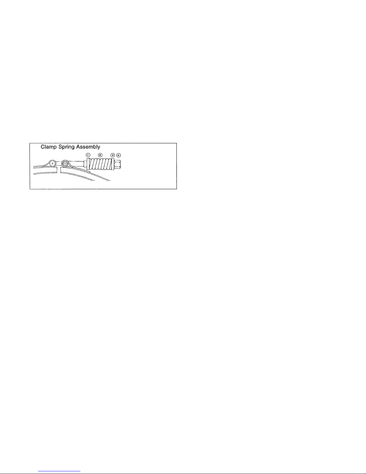
REMOVE CLAMP TAPE. DO NOTLEAVE TAPE EXPOSED TO SUN.
MAKE SURE CLAMP IS LOCATED AND CENTERED PROPERLY
OVER THE FILTER FLANGE.
BOTH SIDES OF THE CLAMP MUST BE TIGHTENED FIRMLY AND
EVENLY UNTIL SPRING COILS TOUCH EACH OTHER (SEE
ILLUSTRATION BELOW).
FINAL SPACE BETWEEN BOTH
CLAMP HALVES
SHOULD BE
EQUAL.
CAUTION: All suction and discharge valves must be open when starting
the system. Failure to do so could result in severe personal injury and/or
property damage.
The following clamp spring assembly, which includes a spring, two
washers (small and large hole) and a sleeve nut, provides a
visual means of ensuring that the clamp is tight.
STARTING THE FILTER
BE SURE CENTER CLAMP IS SECURE. Be sure filter drain plug
is closed. Open Air Relief Valve at top of filter a few turns. Open
suction and return valves (when used). Stand clear of filter and
prime and start the pump, following the manufacturer’s
instructions. Air trapped in the system will automatically vent to the
pool and out the Air Relief Valve. Close Air Relief Valve when a
steady stream of water emerges.
FILTERING
Filtration starts as soon as flow is steady through the filter. As the
filter cartridge removes dirt from the pool water, the accumulated
dirt causes a resistance to flow. As a result, the gauge pressure
will rise and the flow will decrease. When the pressure rises 7-10
psi (.49-.69 Bar) above the starting pressure, or when flow
decreases below desired rate, clean or replace the filter cartridges.
CLEAN/REPLACE CARTRIDGES
Removing Cartridge Elements
Shut off the pump.
If filter is located below water level, close valves (or block off
suction and discharge lines) to prevent backflow of water from
pool.
Unscrew and remove drain plug and allow water to drain from
filter. Close drain plug. (Note: To assist draining process,
open air vent a few turns.)
Disassembly:
Using a 9/16” wrench, alternately loosen both clamp
sleeve nuts. Remove one clamp sleeve nut assembly
(spring, two washers and sleeve nut) and carefully remove
clamp.
To remove Filter Head, tap it on the side to break seal at
center of tank OR insert a blunt screwdriver into one of the
notches located behind Connector Fittings, or 90˚ to the
left
of the Connector Fittings, and twist to lift filter head
slightly. DO NOT grasp gauge assembly when removing
filter head—breakage will result.
To Remove Cartridges:
Lift off top closure plate.
Remove cartridges from bottom collector manifold by using
a slight rocking motion and lifting up.
Clean cartridge. (see Cleaning Cartridges)
Reinstalling Cartridges
Flush and drain any dirt or debris from the bottom of the filter
tank.
Carefully replace cartridges over hubs on bottom manifold.
Place top closure plate securely into top of cartridges.
Clean and lightly lubricate Tank O-ring and carefully place
over Filter Body lip.
Clean Filter Head flange sealing surface, and place over Tank
O-ring, pressing down firmly and evenly to seat the Filter
Head in place.
Replace Clamp Assembly. Make sure clamp is located and
centered properly over the filter flange. If Clamp is tight, tap
Clamp with rubber mallet or block of wood to help seat it.
Insert threaded stud through retainer and secure with Clamp
Spring Assembly (be sure to position small and large hole
washers properly—see illustration in IMPORTANT SAFETY
INSTRUCTIONS).
In some cases it may be necessary to use the two-part filter
clamp to assist in assembling the filter cover to the filter base.
With one nut, spring and washer assembly already removed,
loosen the remaining clamp nut to maximize clamp opening. If
Clamp is tight, tap Clamp with rubber mallet or block of wood
to help seat it as you are tightening nuts. If the two (2) clamp
springs (DE2400JS) are temporarily removed in order to fully
extend the clamp bolts, the clamp springs and washers MUST
be reassembled as shown in the CLAMP SPRING ASSEMBLY
diagram in IMPORTANT SAFETY INSTRUCTIONS.
Tighten sleeve nuts alternately to secure Clamp firmly and
evenly to form a good seal (be sure spring coils touch each
other and final space between Clamp halves is even—see
illustration in IMPORTANT SAFETY INSTRUCTIONS).
Install Drain Plug, open pool suction and return valves and
proceed as in STARTING THE FILTER.
Cleaning Cartridges
The cartridge filter element can be cleaned by pressure washing
inside and out with a garden hose. (The cartridge is easier to
clean when dry.) After hosing the cartridge, for best results, allow
cartridge to dry and carefully brush pleated surface areas to
remove fine particles.
Algae, suntan oil and body oils can form a coating on the cartridge
pleats which may not be thoroughly removed by hosing. To remove
such materials, soak the cartridge in a solution of filter element
cleaner (various brands are available at pool dealer). Follow
manufacturer’s directions for use and allow an hour for soaking.
Hose thoroughly before reinstalling the filter.
If calcium or mineral deposits are excessive, the cartridge may be
restored to “like new” condition by soaking in muriatic acid. Use
commercially available 20% muriatic acid added to water in 1 to 1
ratio. Use a plastic container and take extreme care when handling
cleaning agents as they can be harmful to eyes, skin and clothing.
After cleaning, flush with water.
A spare cartridge filter element is an excellent investment. It
provides convenience and ensures that your filter will always be
ready to operate at peak efficiency.
Hayward cartridges are specifically designed and engineered for
use in Star-Clear filters. For best results, use only genuine
Hayward Star-Clear cartridges in your filter. Order
Model No.
CX470XRE, CX570XRE, CX870XRE or CX1260RE
from your
dealer. The Hayward name is your guarantee of quality.
VACUUMING
Vacuuming can be performed directly into the filter whenever
needed. Clean cartridges after vacuuming, if required.
•
•
•
•
1.
2.
3.
4.
a.
b.
5.
a.
b.
c.
1.
2.
3.
4.
5.
6.
1.
2.
3.
4.
DEX2400J4
Washer w/Small Hole
DEX2400JS
Spring
DEX2400J3
Washer w/Large Hole
DEX2400JN
Brass Sleeve Nut
 Loading...