

Hayward Super Pump 700, Super Pump SP2670010X15, Super Pump SP2670007X10 Owner's Manual
Super Pump
Owner’s Manual
IS26700T Rev-A
®
700 Series
Contents
Product Specific Warnings………2
Introduction……….………………..…4
Installation……….……………..….….7
Shaft Seal Replacement..………..8
Replacement Parts………….……..10
Troubleshooting………….…..…….11
Warranty…………………………………13
Registration ……………………..……15
IMPORTANT SAFETY INSTRUCTIONS
Basic safety precautions should always be followed, including the following: Failure to follow instructions
can cause severe injury and/or death.
This is the safety-alert symbol. When you see this symbol on your equipment or in this manual, look for
one of the following signal words and be alert to the potential for personal injury.
WARNING warns about hazards that could cause serious personal injury, death or major property
damage and if ignored presents a potential hazard.
CAUTION warns about hazards that will or can cause minor or moderate personal injury and/or
property damage and if ignored presents a potential hazard. It can also make consumers aware of
actions that are unpredictable and unsafe.
The NOTICE label indicates special instructions that are important but not related to hazards.
Hayward Pool Products
620 Division Street, Elizabeth, NJ 07207
Phone: (908) 355-7995
www.hayward.com
USE ONLY HAYWARD GENUINE REPLACEMENT PARTS 1
N
a
N
s
a
t
u
e
N
Wbe
p
h
e
ngu
n
N
u
N
a
N
a
T
d
N
o
p
e
g
N
n
n
m
d
w
h
a
b
e
w
v
e
e
c
r
i
i
y
o
e
o
w
v
i
s
a
n
o
e
a
c
e
a
o
s
Y
n
c
e
n
a
e
e
a
t
e
n
k
p
c
c
e
p
s
e
r
g
u
m
t
r
m
n
I
i
e
l
e
w
m
o
a
r
n
y
a
e
o
e
e
m
o
m
a
m
o
m
o
n
.
e
a
c
p
a
o
a
b
e
r
o
A
r
/
m
.
t
b
o
c
m
w
s
n
m
a
e
l
a
a
t
h
p
r
s
t
u
c
t
m
m
t
v
d
d
w
t
R
h
o
g
u
i
s
o
o
i
s
w
s
u
n
s
m
r
p
e
s
p
i
e
t
e
a
r
n
a
k
s
a
i
i
E
f
.
s
o
t
e
r
u
u
t
o
s
d
s
D
o
g
y
t
e
e
n
n
a
f
u
i
r
e
a
o
o
e
e
f
e
m
o
o
p
n
t
t
t
e
o
s
r
e
d
Suction in
severe inju
Hair Entra
Limb Entr
cracked, m
Body Suc
Eviscerati
sump or s
disembow
Mechanic
opening of
suction o
material c
replaced
being use
on this pro
positioned
WAR
WAR
WAR
o
o D
o D
o T
o N
o R
o I
o I
WAR
WAR
WAR
CAU
ING
–
Rea
F
ilure to follo
ING
– Suct
uction outlets
ry and/or deat
pment
- Hair c
pment
- A lim
issing, or not s
ion Entrapm
on/ Disembo
ction outlet co
lment.
l Entrapmen
a suction outl
ING
- To Re
hen outlets ar
installed. Su
a
art, as measu
ual suction fitt
ual suction fitt
e maximum s
ever use Pool
place damag
addition two
idelines, follo
stallation of a
ING
–
tlets can resu
ING
–
n result in an
ING
–
t least every s
ION
–
Comp
as means of
uct. Closely
to prevent chil
, understa
instructions
ion Entrapm
and/or suctio
due to the fol
n become ent
inserted into
ecurely attach
nt
elment
er which is, d
- There is pot
t cover resulti
duce the ris
small enough
tion outlets in
ed from near
ngs shall be pl
ngs shall not b
stem flow rate
r Spa if any su
d, broken, cra
r more suction
all National,
acuum releas
Failu
re to remove
lt in an increa
Failu
re to keep suc
increase pot
Suct
on outlet com
even years or
onents such a
access to the
upervise child
dren from usin
- A negative
- A n
d, and fol
an cause sev
nt Hazard.
outlet covers
lowing entrap
ngled in sucti
an opening of
d can result in
pressure appli
gative pressu
maged, broke
ntial for jewelr
g in mechanic
of Entrapm
to be blocked
the same plan
oint to near po
aced in such l
e located on s
shall not exce
tion outlet co
ked, missing,
outlets per pu
State, and Loc
or vent syste
ressure test p
e potential f
tion outlet co
ntial for sucti
ponents have
if found to be
s the filtratio
pool by young
en at all times
them as a m
ow all inst
re injury and
hich are, da
ent hazards:
n outlet cover
suction outle
a mechanical
d to a large p
e applied dire
, cracked, mis
, swimsuit, ha
l entrapment.
nt Hazards:
by a person, a
e (i.e. floor or
int.
cations and di
ating areas or
d the flow rati
ponent is da
r not securely
p installed in
l codes applic
, which reliev
lugs and/or p
r suction entr
ponents cle
n entrapmen
a finite life, t
damaged, bro
system, pum
children. To
Components
ans of access
uctions
or death.
aged, broken,
sump or sucti
ind or swellin
rtion of the bo
tly to the intes
sing, or unsec
ir decorations,
minimum of tw
all), must be i
stances to avo
on the backre
g of as listed
aged, broken,
attached sucti
accordance w
able.
s entrapping
lugs used in
pment as de
r of debris, s
as described
e cover/grate
ken, cracked,
ps and heater
educe risk of i
such as the filt
o the pool.
in t
his owner’s m
cracked, missi
on outlet cove
of the limb.
dy or limbs ca
tines through
red can result
finger, toe or
o functioning
nstalled a mini
d “dual block
t for such seat
n Table 1.
cracked, miss
n outlet comp
th latest ASM
uction, is reco
interization o
cribed above
ch as leaves,
above.
should be in
ration system,
missing, or n
must be posi
jury, do not p
nual and on
ng, or unsecur
that is damag
result in an e
n unprotected
in evisceratio
nuckle to be c
uction outlets
mum of three
ge” by a user.
ng areas.
ng, or not sec
onents immed
, APSP Standa
mmended.
the pool/spa
dirt, hair, pap
pected frequ
t securely att
ioned so as t
rmit children t
pumps, and h
he equipmen
d can cause
d, broken,
trapment.
suction outlet
/
ught in an
per pump mus
eet (3’) [1 met
rely attached.
ately.
ds and CPSC
from the
er and other
ntly and
ched.
prevent their
use or climb
aters must be
.
r]
WAR
start up, n
follow safe
and clamp
pool and s
be in open
back to th
open filter
is dischar
WAR
of pump a
servicing p
circulation
circulation
circulatio
air can cau
high volu
ING
– Haz
rmal operatio
ty and operati
due to pressur
a water circul
position. Befo
pool. Do not
manual air reli
ed.
ING
– Sep
d/or filter com
ool and spa cir
system if a sys
system unless
system at m
se component
e blower when
rdous Press
, and after pu
n instructions
in the system
tion system, a
re starting sys
hange filter co
f valve. Do no
ration Haza
ponents. Strai
culation syste
tem compone
filter manual a
re than 50 PS
to explode, w
air purging th
re.
Pool and
p shut off. St
could result in
, which could
ll system and
em pump, all s
ntrol valve pos
t close filter m
d.
Failure to f
ner cover must
, filters manu
t is not assem
ir relief valve b
. Do not purg
th risk of seve
pump, filter,
spa water circ
nd clear of cir
violent separa
ause property
ump controls
ystem valves
ition while sys
nual air relief
llow safety an
be properly se
l air relief valv
led properly,
ody is in locke
the system
e injury or dea
r piping.
lation system
ulation syste
ion of the pum
damage, seve
ust be in off
ust be set in a
em pump is ru
alve until a st
d operation in
cured to pump
e must be in o
amaged, or m
position in fil
ith compress
h to anyone n
operate unde
equipment d
p housing and
e personal inj
osition and fil
position to all
nning. Before
ady stream of
tructions coul
housing with
en position.
ssing. Do not
ter upper body
ed air. Purgin
arby. Use onl
hazardous pr
ring pump sta
cover, and/or
ry, or death. B
er manual air r
w system wat
tarting syste
water (not air
result in viole
trainer cover l
o not operate
perate pool a
. Never opera
the system wi
a low pressur
ssure during
rt up. Failure t
ilter housing
efore servicing
elief valve mu
r to return
pump, fully
r air and wate
nt separation
ck ring. Befor
ool and spa
d spa
e or test the
th compresse
e (below 5 PSI)
t
)
USE ONL
HAYWARD G
ENUINE REPL
CEMENT PA
TS
2
WARNING – Risk of Electric Shock. All electrical wiring MUST be in conformance with applicable local codes,
regulations, and the National Electric Code (NEC). Hazardous voltage can shock, burn, and cause death or serious property
damage. To reduce the risk of electric shock, do NOT use an extension cord to connect unit to electric supply. Provide a properly
located electrical receptacle. Before working on any electrical equipment, turn off power supply to the equipment. To reduce
the risk of electric shock replace damaged wiring immediately. Locate conduit to prevent abuse from lawn mowers, hedge
trimmers and other equipment. Do NOT ground to a gas supply line.
WARNING – Risk of Electric Shock Failure to ground all electrical equipment can cause serious or fatal electrical shock
hazard. Electrical ground all electrical equipment before connecting to electrical power supply.
WARNING – Risk of Electric Shock Failure to bond all electrical equipment to pool structure will increase risk for
electrocution and could result in injury or death. To reduce the risk of electric shock, see installation instructions and consult a
professional electrician on how to bond all electrical equipment. Also, contact a licensed electrician for information on local
electrical codes for bonding requirements.
Notes to electrician: Use a solid copper conductor, size 8 or larger. Run a continuous wire from external bonding lug to
reinforcing rod or mesh. Connect a No. 8 AWG (8.4 mm
pressure wire connector provided on the electrical equipment and to all metal parts of swimming pool, spa, or hot tub, and metal
piping (except gas piping), and conduit within 5 ft. (1.5 m) of inside walls of swimming pool, spa, or hot tub.
IMPORTANT - Reference NEC codes for all wiring standards including, but not limited to, grounding, bonding and other general
wiring procedures.
2
) [No. 6 AWG (13.3 mm2) for Canada] solid copper bonding wire to the
WARNING – Risk of Electric Shock . The electrical equipment must be connected only to a supply circuit that is protected
by a ground-fault circuit-interrupter (GFCI). Such a GFCI should be provided by the installer and should be tested on a routine
basis. To test the GFCI, push the test button. The GFCI should interrupt power. Push reset button. Power should be restored. If
the GFCI fails to operate in this manner, the GFCI is defective. If the GFCI interrupts power to the electrical equipment without the
test button being pushed, a ground current is flowing, indicating the possibility of an electrical shock. Do not use this electrical
equipment. Disconnect the electrical equipment and have the problem corrected by a qualified service representative before
using.
CAUTION – HAYWARD
spas if so marked. Do not use with storable pools. A permanently-installed pool is constructed in or on the ground or in a
building such that it cannot be readily disassembled for storage. A storable pool is constructed so that it is capable of being
readily disassembled for storage and reassembled to its original integrity.
®
pumps are intended for use with permanently-installed pools and may be used with hot tubs and
WARNING – Risk of Hyperthermia. To avoid hyperthermia the following “Safety Rules for Hot Tubs” are recommended by
the U.S. Consumer Product Safety Commission.
1. Spa or hot tub water temperatures should never exceed 104°F [40°C]. A temperature of 100°F [38°C] is
considered safe for a healthy adult. Special caution is suggested for young children. Prolonged immersion
in hot water can induce hyperthermia.
2. Drinking of alcoholic beverages before or during spa or hot tub use can cause drowsiness, which could
lead to unconsciousness and subsequently result in drowning.
3. Pregnant women beware! Soaking in water above 100°F [38°C] can cause fetal damage during the first
three months of pregnancy (resulting in the birth of a brain-damaged or deformed child). Pregnant women
should adhere to the 100°F [38°C] maximum rule.
4. Before entering the spa or hot tub, users should check the water temperature with an accurate thermometer; spa or hot tub thermostats may err in regulating water temperatures by as much as 4°F
(2.2°C).
5. Persons taking medications, which induce drowsiness, such as tranquilizers, antihistamines or anticoagulants, should not use spas or hot tubs.
6. If the pool/spa is used for therapy, it should be done with the advice of a physician. Always stir pool/ spa water
before entering the pool/spa to mix in any hot surface layer of water that might exceed healthful temperature
limits and cause injury. Do not tamper with controls, because scalding can result if safety controls are not in
proper working order.
7. Persons with a medical history of heart disease, circulatory problems, diabetes or blood pressure
problems should obtain a physician’s advice before using spas or hot tubs.
8. Hyperthermia occurs when the internal temperature of the body reaches a level several degrees above normal
body temperature of 98.6°F [37°C]. The symptoms of Hyperthermia include: drowsiness, lethargy,
dizziness, fainting, and an increase in the internal temperature of the body.
The effects of Hyperthermia include:
1. Unawareness of impending danger.
2. Failure to perceive heat.
3. Failure to recognize the need to leave the spa.
4. Physical inability to exit the spa.
5. Fetal damage in pregnant women.
6. Unconsciousness resulting in danger of drowning.
SAVE THESE INSTRUCTIONS
USE ONLY HAYWARD GENUINE REPLACEMENT PARTS 3
General Information
Introduction
This manual contains information for the proper installation and operation of the Hayward Super Pump® 700 Series.
The instructions in this manual MUST be followed precisely. Failure to install according to defined instructions
will void warranty.
Product Benefits
Super-sized 110 cubic-inch basket has extra leaf-holding capacity and extends time between cleanings. Rigid
construction with load extender ribbing assures free flowing operation even with heavy debris loads.
Exclusive swing-aside hand knobs make strainer cover removal simple and easy.
See-thru strainer cover lets you see when the basket needs cleaning.
All components molded of corrosion-proof reinforced thermoplastic for extra durability and long life.
Uni-bracket mounting base provides stable, stress-free support, plus versatility for any installation requirement.
Adapts to 48 and 56 frame motors.
Heat resistant, industrial size ceramic seal.
Rugged, one-piece housing, with full-flow ports, assures rapid priming and continuous operation.
Service-ease design gives simple access to all internal parts. By disengaging just four (4) bolts, motor and
entire drive group assembly can be removed, without disturbing pipe or mounting connections.
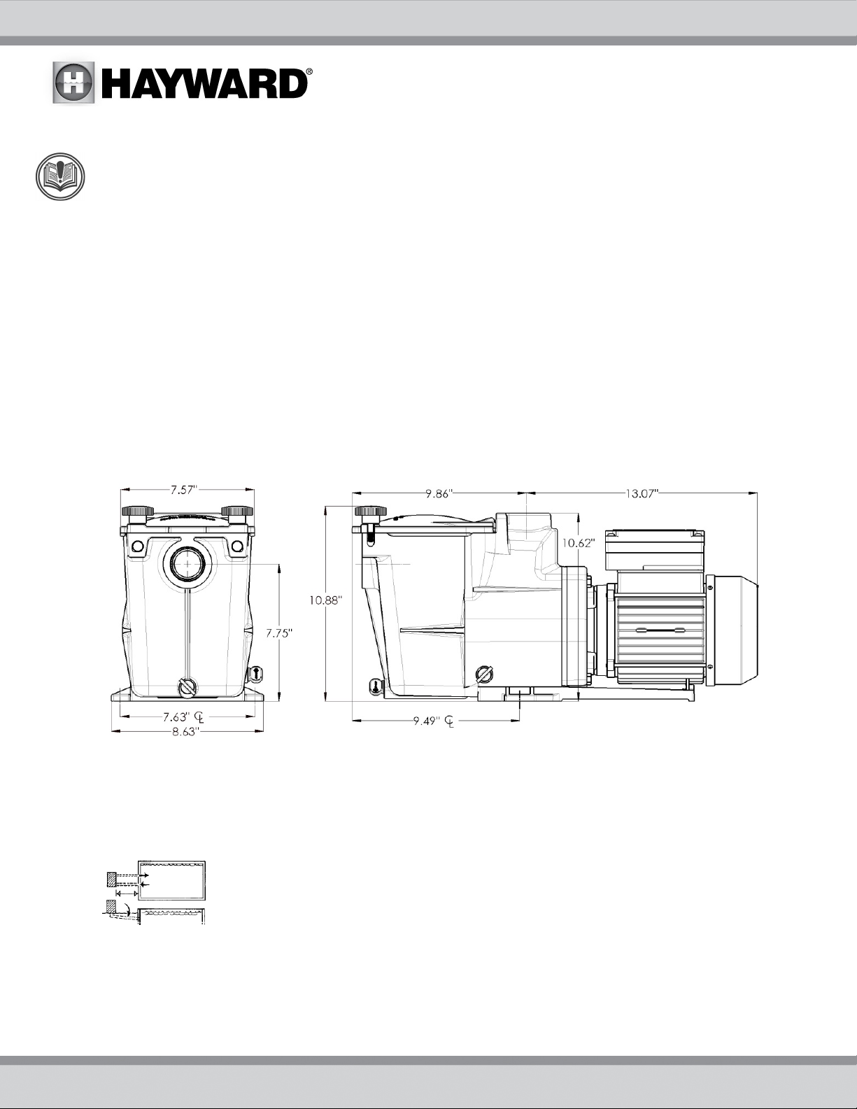
Product Specifications
Installation Instructions
NOTICE
Pump Location
Though the pump is designed for outdoor use, it is strongly advised to protect the electrical components from the
weather. Select a well-drained area, one that will not flood when it rains. Do NOT install pump in a damp or nonventilated location. Keep motor clean. Pump motors require free circulation of air for cooling.
– This product should be installed and serviced only by a qualified professional.
Locate pump as close to pool as practical and run suction lines as direct as possible to reduce
friction loss. Suction lines should have continuous slope upward from lowest point in line.
Joints must be tight (but not over-tightened). Suction line diameter must equal or be larger than
the discharge line diameter.
USE ONLY HAYWARD GENUINE REPLACEMENT PARTS 4
Pump Mounting
Install pump on a firm, level base or pad to meet all local and national codes. Fasten pump to base or pad with
screws or bolts to reduce vibration and stress on pipe or hose joints. The base MUST be solid, level, rigid, and
vibration free.
Pump mount must:
Allow pump inlet height to be as close to water level as possible.
Allow use of short, direct suction pipe (to reduce friction losses).
Allow for ball valves in suction and discharge piping.
Be protected from excess moisture and flooding.
Allow adequate access for servicing pump and piping.
Incorporate a straight portion of pipe prior to pump inlet no less than (5) pipe diameters in length.
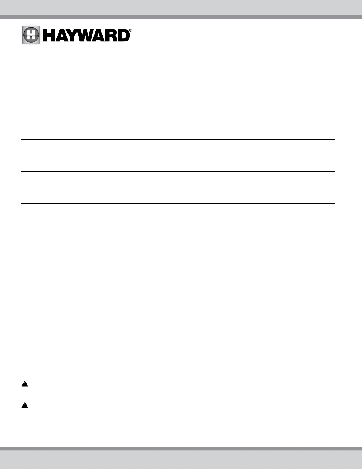
Pipe Sizing Chart
MAXIMUM RECOMMENDED SYSTEM FLOW RATE BY PIPE SIZE
Pipe Size Flow rate Water Velocity Pipe Size Flow rate Water Velocity
inches [mm] GPM [Liter/Min] ft/sec [meters/sec] inches [mm] GPM [Liter/Min] ft/sec [meters/sec]
1 ½” 50.76 8 2 ½” 119 8
[50] [192] [2.44] [75] [452] [2.44]
2” 84 8 3” 184 8
[63] [317] [2.44] [90] [698] [2.44]
NOTE – System design should allow a maximum of 8-ft/sec [2.44 meters/sec] water velocity in residential pool or spa
piping. It is recommended that a minimum length of piping, equivalent to 10 pipe diameters, be used between the
pump suction inlet and any plumbing fittings.
Plumbing
Use PTFE tape to seal threaded connections on molded plastic components. All plastic fittings must be new or
thoroughly cleaned before use. NOTE - Do NOT use Plumber’s Pipe Dope as it may cause cracking of the plastic
components.
When applying PTFE tape to plastic threads, wrap the entire threaded portion of the male fitting with one to two
layers of tape. Wind the tape clockwise as you face the open end of the fitting, beginning at the end of the fitting.
The pump suction and outlet ports have molded-in thread stops. Do NOT attempt to force hose connector fitting
past this stop. It is only necessary to tighten fittings enough to prevent leakage. Tighten fitting by hand and then
use a tool to engage fitting an additional 1 ½ turns. Use care when using PTFE tape as friction is reduced
considerably; do NOT over-tighten fitting or you may cause damage. If leaks occur, remove connector, clean off
old PTFE tape, re-wrap with one to two additional layers of PTFE tape, and re-install connector.
Fittings
Fittings restrict flow. For better efficiency, use the fewest possible fittings. Avoid fittings that could cause an air
trap. Use two or more suction outlets per pump installed in accordance with latest ASME, APSP Standards and CPSC
guidelines, follow all National, State, and Local codes applicable.
Electrical
NOTICE – All wiring must be done by a licensed electrician and must conform to all local and national codes
and regulations.
WARNING – Risk of Electric Shock. Before working on any electrical equipment, turn off power supply to the
equipment.
WARNING – Fire Hazard. Match supply voltage to motor nameplate voltage.
Insure that the electrical supply available agrees with the motor’s voltage, phase, and cycle, and that the wire size is
adequate for the HP (kW) rating and distance from the power source. NOTE - All electrical wiring MUST be
performed by a licensed electrician, and MUST conform to local codes and NEC regulations
.
USE ONLY HAYWARD GENUINE REPLACEMENT PARTS 5
 Loading...