

HAYWARD SUMMIT User Manual
OWNER’S Manual
PRINTED IN CANADA 10/2009


Introduction 2
General Safety Instructions 4
Installation Instructions
Location 6
Water piping 7
Electrical 7
Bonding 8
Bonding and plumbing step-by-step instructions 8
Using an External Controller 10
Electrical Connections 11
Wiring Diagram 12
Service Analyzer Control 13
Operation 14
Caring for your Pool Heater 15
Initial Startup 16
Meaning of Display Codes 17
Troubleshooting 18
Requesting Assistance or Service 20
Maintenance 21
Winterizing 21
Hayward
®
Heat Pump Pool Heater Limited Warranty 22
International Warranty 23
Notes 24
Warranty Card Registration 25
Table of contents
OWNER’S MANUAL

2
OWNER’S MANUAL
Thank you for buying
a SUMMIT pool heat pump.
The SUMMIT pool heat pump is a self-contained unit designed specifi cally for
pool heating. Each component has been selected with care to achieve a highquality product in an effort to exceed all industry standards.
All SUMMIT pool heat pumps have an electronic board with service analyzer,
a titanium heat exchanger tube warranted for 10 years against corrosion and
a UV-resistant plastic cabinet that eliminates all maintenance for life. All components are of superior quality, which presents you with an effective, state-ofthe-art technology heat pump.
Compared to other types of pool heaters, such as gas or oil-fi red, the
SUMMIT pool heat pump has a lower heating capacity on a BTU/hr
basis. Therefore, it needs to operate for a longer time to accomplish the
desired results. Occasionally, it may be necessary to run the heat pump for
up to 24 hours per day. However, this should not be of concern to the owner
because the heater is designed to operate continuously. What’s more, despite
continuous operation, it will still heat the pool far more economically than other
types of heaters.
As with all pool heaters, you are advised to use a pool cover at night and when
the pool is not in use. The pool cover should be used if night temperatures are
15°F less than desired pool temperature. This will keep evaporation, the greatest
source of heat loss, to a minimum, thus greatly reducing the overall pool heating
costs. During warmer weather, the pool cover may not be required.

Please read carefully
Record your model’s information
Please complete and mail in the ownership registration card provided with
this guide. The return address is displayed on the front of your registration
card. Simply mail it as you would a postcard. The card helps us notify you
about any new information about your heater.
Whenever you call to request service for your heater, you must know your
complete model and serial numbers. You can fi nd this information on the
plate located at the base of your heater.
Please also record the purchase date of your device and your dealer’s name,
address, and telephone number.
Model Number ____________________________________________________
Serial Number _____________________________________________________
Purchase Date ____________________________________________________
Dealer Name ______________________________________________________
Dealer Address ____________________________________________________
Dealer Phone _____________________________________________________
Keep this book and the sales slip together in a safe place for future reference.
3
Service can now be obtained by calling
these phone numbers.
CANADA: 1 888 238-7665
USA: 1 908 355-7995
OWNER’S MANUAL
General Safety Instructions
We care for our customers
We have provided important safety messages in this manual and on your
heater. Always read and obey all safety messages.
IMPORTANT
The IMPORTANT sign calls attention to a note that provides important
information or information essential to the completion of a task.
CAUTION
The CAUTION sign denotes a hazard. It calls attention to an operating
procedure, practice, or the like, which, if not correctly performed or
adhered to, could result in material damage, particularly to the product,
up to the destruction of part or all of the product.
WARNING
The WARNING sign denotes a hazard. It calls attention to a procedure,
practice, or the like, which, if not correctly performed or adhered to,
could result in personal injury or injury to a third party. These signs are
rare, but are extremely important.
?
!
4
OWNER’S MANUAL

CAUTION
All electrical connections must be done by a qualifi ed electrician and
according to the local electrical codes. Always cut off the unit’s main
power whenever the access panel is open or removed. Always install the
machine outdoors (unless otherwise approved by the manufacturer),
while respecting the minimal clearances needed for proper operation
and heating.
!
CAUTION
Proper pool chemistry is vital to the life of your heater. Pay particular
attention to the total alkalinity and TDS. It is highly recommended that you
have your pool chemistry checked often by an independent pool store.
!
5
OWNER’S MANUAL
Installation Instructions
Location
The placement of the pool heater is very important in keeping installation
costs to a minimum while providing for maximum effi ciency of operation, as
well as allowing adequate access for service and maintenance.
The pool heat pump is designed for outdoor installation and should
not be installed in a fully enclosed area, such as a shed, garage, etc.
Recirculation of cold discharged air back into the evaporator coil will greatly
reduce unit heating capacity and effi ciency.
The unit should be located as close as practical to the existing pool pump and
fi lter to minimize water piping. However, do not forget to provide a 24”clearance at the very least all around your heat pump. The use of 90 degree bends
and short radius elbows in the water piping should be kept to a minimum.
Mount the unit on a sturdy base, preferably a concrete slab or a set of blocks.
The base should be completely isolated from the building foundation wall to
prevent the possibility of sound or vibration transmission into the building.
The size of the base should not be less than 36” x 36” (92 cm x 92 cm).
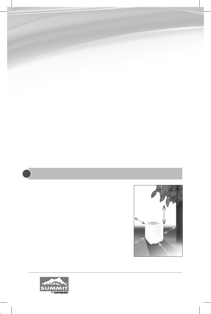
Air is pulled through the evaporator coil and
discharged through the top grille. A minimum
clearance of 72 inches should be allowed above
the unit for unrestricted air discharge. The unit
must not be installed under a porch. Any side of
the unit should be located at least 24 inches from a
wall or from any other obstruction for unrestricted
air intake and service access.
IMPORTANT
?
72”
24”
24”
24”
Service access
24” to 36”
6
OWNER’S MANUAL
Water piping
The piping sequence is as follows: pool > pool pump > fi lter > heater > check
valve > chemical feeder > pool. Automated chlorine distribution systems, if
used, must be placed downstream of the heater to minimize harm to the pool
equipment. Use rigid PVC piping if possible (SCH40 or SCH80). All joints
should be glued with PVC glue. When the piping installation is complete,
operate the pool pump and check the system for leaks. Then, check the fi lter
pressure gauge to verify that there isn’t any indication of excessive pump
head pressure.
You can also make the connections using high-pressure fl exible hose, but
make sure the hose can withstand high pressure. The installation of a heat
pump bypass is not necessary unless the water fl ow exceeds 75 GPM.
Note: Certain installations have valves which isolate the heat pump from the water circuit. If the heat exchanger
is deprived of water circulation for several days, high chlorine gas could cause excessive corrosion. If the disconnect
switch is turned off, be sure that the pool water is allowed to circulate through the unit, or is drained out of it.
Electrical
The wiring of your pool heat pump should be performed by a qualifi ed
electrician in accordance with local requirements.
A properly-sized breaker and copper wire must be used.
Check the heat pump data label for required maximum breaker size.
The unit must always be powered off before opening the access panel.
IMPORTANT
?
CAUTION
!
WARNING
7
OWNER’S MANUAL
 Loading...