

Hayward HP20854T, HP20654TC, HP20854TC, HP20854BT, HP21104TC Troubleshooting Manual
...
Hayward/Summit Heat Pump
Troubleshooting Guide
© 2012 Hayward Industries

Leave Blank- Inside Front Cover

Heat Pumps Covered by This Guide
HeatPro
HP50TA, HP20654T, HP20654BT, HP20654TC, HP20854T, HP20854BT, HP20854TC,
HP21104T, HP21104TC, HP21404T
Note: HP50TA, and HP21404T heat pumps while labeled as HeatPro,
are built on the Summit platform.
Use Summit wiring diagrams, and error codes in your diagnostics
Summit/ HeatMaster/ EnergyTherm/ EasyTemp
SUM25TA, SUM3TA, SUM3TAC, SUM4TA, SUM4TAC, SUM5TA, SUM5TAC
SUM8TA, HML50TA, HML65TA, HML65TAC, HML80TA, HML80TAC, HML110TA
HML110TAC, HML125TA, HET50BTA, HET65BTA, HET110BTA, HET125BTA
HCB50BTA, HCB65BTA, HCB65BTAC, HCB80BTA, HCB80BTAC, HCB110BTA,
HCB110BTAC

Table of Contents
Important Safety Information
1
HeatPro Parts Diagram
18
Basic Operation of Heat Pump
2
HeatPro Parts List
19
Normal Operation of Heat Pump
3-4
Summit/EasyTemp/HeatMaster Parts Diagram
20
Setting Heat Pumps for Remote Operation
5-6
Summit/EasyTemp/HeatMaster Parts List
21
Common Error Codes LP
7
HeatPro Wiring Diagram
22
Common Error Codes HI/HP
8
Summit/EasyTemp/HeatMaster Wiring Diagram
23
Common Error Codes PO/OP
9
Summit/EasyTemp/HeatMaster Setup Menu
24
Common Error Codes Pc/SH
10
Heat Pump Specifications
25
Common Error Codes dPO/cOP
11
Flow Charts PS/Flo
26
Common Error Codes dPc/cSH
12
Flow Charts HI/HP
27
Temperature/Resistance Charts
13
Flow Charts OP/PO- SH/Pc
28
Common Error Codes Flo/PS
14
Flow Charts cOP/dPO - cSH/dPc
29
Common Error Codes Blank Display
15
Flow Charts LP
30
Common Error Codes Fs/dEF
16
Alternative Leak Detection Methods
31
Hot Gas Bypass
17

!
High voltage. Danger! Use
extreme caution. Do not
attempt if you are not a
qualified servicer.
Warning!
The following heat pump Troubleshooting Guide is to be used in diagnosing and repairing Hayward &
Summit branded pool heat pump systems containing R-410A refrigerant . They are not intended for use
with any other manufacturers heat pumps.
Heat Pump pool heaters are similar to the heat pumps for home heating and cooling in that they contain
refrigerant. As such, service personnel should observe EPA regulations for refrigerant handling. Pool heat pumps
operate on 240 volts A/C. There is a risk of electric shock at all terminals and the heat pump should only be
serviced by trained personnel.
To use this guide, determine the model number of the heat pump and the nature of the problem. Refer to
the Table of Contents to find the appropriate page for the problem and follow the flow charts to the solution.
If you have further questions:
Contact Hayward’s Technical Service Department at 908-355-7995
Safety

Heat Pro and Summit heat pumps generally operate in the same fashion. Power is connected to
the contactor per the installation instructions. Ensure the water line ‘in’ and ‘out’ connections are
correct. Set the control for pool or spa operation. Adjust the thermostat setpoint above the water
temperature. In approximately 3 to 5 minutes the heat pump will begin ‘heating’. This 3 to 5 minute
delay is important as it protects the compressor from short cycling. This time delay is part of the
control circuit of the heat pump.
Hayward Heat Pro units have a 5 minute delay during which no operation will occur.
Summit brand units have a 3 minute delay, but the fan will come on immediately once the heat pump
is turned on and the thermostat raised to a setpoint above the pool temp.
The time delay will delay the start of the heat pump any time power is interrupted to the heat pump.
When the heat pump satisfies the thermostat and shuts off, the time delay will not allow
the heat pump to restart for 3-5 minutes.
The thermostat will turn the heat pump on and off
as needed to keep the pool at the desired temperature.
Note: Heat pumps will not operate when the pool pump is off.
Basic Operation of Heat Pump

Normal Operation of Heat Pump
All of the heat pumps covered in this guide are charged with R-410A refrigerant
If you have a system that is charged with R-22 refrigerant, and require assistance
call our Technical Support Department at 908-355-7995
Normal Refrigerant Operating Pressures
Low side 125-135psi
Lower ambient temperatures will result in lower low side (suction) pressures.
High Side 290-400psi
Higher water temperatures will result in higher high side (discharge) pressures.
Normal Air Temperature Differential
This is the difference in the temperature of the air entering the coil (ambient air),
and the air being discharged out the top by the fan.
15-20 degrees Fahrenheit
Low relative humidity and/or lower than normal ambient temperatures can cause
lower than normal temperature differentials.
Note: This is the best way to determine if a heat pump is heating

Normal Operation of Heat Pump
Water In and Around Heat Pump
The heat pump evaporator coil (the surrounding coil) condenses moisture out
out of the surrounding air. As much as 3-5 gallons per hour of run time
is common in higher humidity areas. This is normal and in fact increases the
efficiency of the heat pump. The heat pump base pan design allows for a drain line
to be attached using readily available components to drain this water away if it is
a problem. In most installation situations however, this moisture simply runs off the
pad and is absorbed into the ground.
Best Methods to Determine if Heat Pump is Actually Leaking
1. If the heat pump is leaking, it will continue to leak even when the heat pump is not running.
If the water you are seeing is condensation from the evaporator coil it
will dry up in a few hours.
2. Test the water with a chlorine test strip. If the water shows no or very low levels of chlorine
the water is condensation. If the test strip shows levels of chlorine similar to pool water,
you may have a leak.
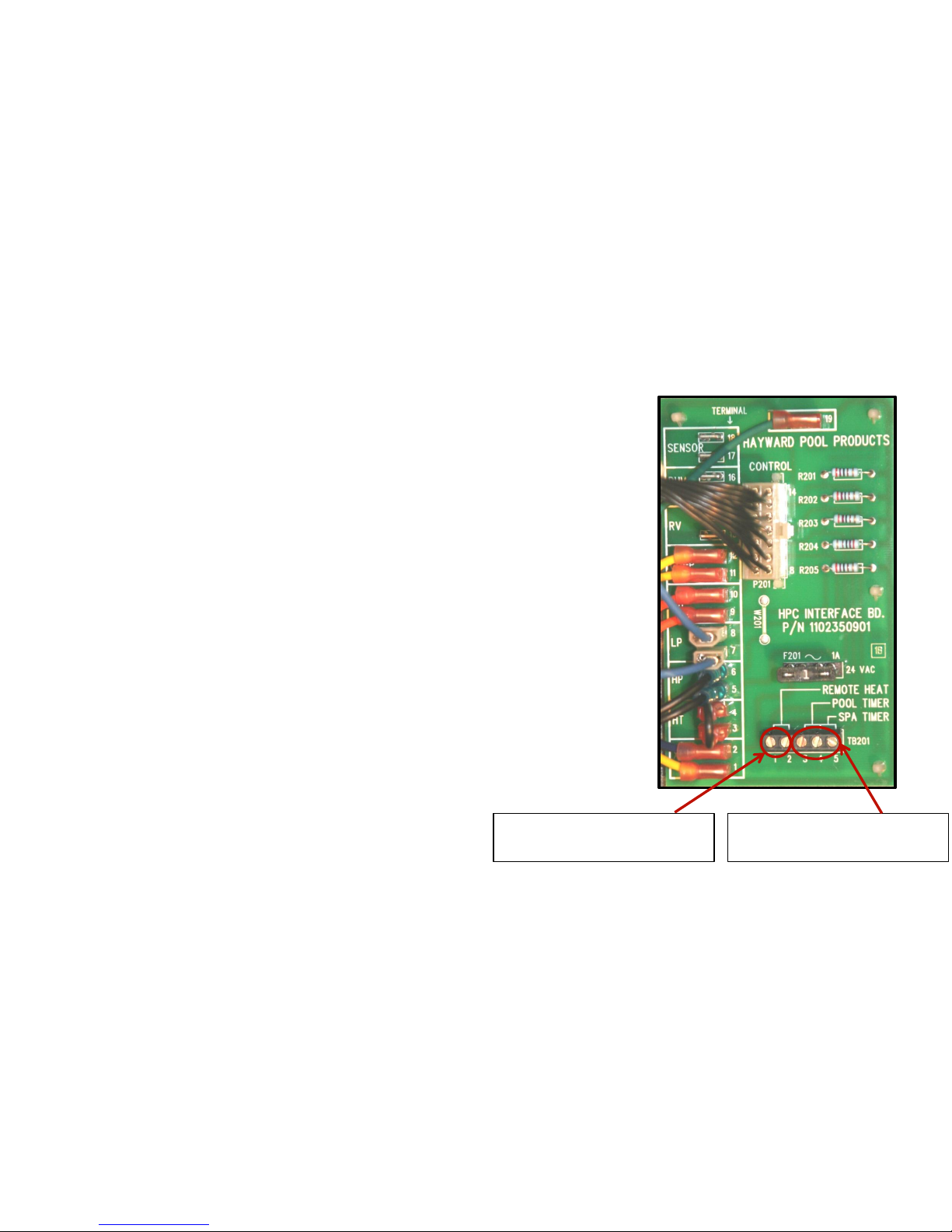
Setting Heat Pumps for Remote Operation
Use Terminals 1 and 2
for 2 wire remote connection
Heat Pro Heat Pumps
For 2 wire remotes such as Hayward’s Pro-Logic, attach the 2 low voltage
wires from remote to terminals 1 and 2 on terminal block TB201. Set heat
pump to standby mode (three red dots scrolling across screen). Heat
pump is now ready for remote operation.
Heat Pro Heat Pumps
For 3 wire remotes where the desired temperature is set on the heat pump,
attach the 3 wires from your remote to the 3, 4 and 5 terminals on terminal
block TB201. Attach the pool wire to terminal 3, the common wire to
terminal 4 and the spa wire to terminal 5. Set both the pool and spa desired
temperature on the heat pump before turning on the remote. Once the
remote is calling for pool or spa you will not be able to change the function
on the heat pump without turning the remote off.
Use Terminals 3,4,& 5
for 3 wire remote connection
Note: Heat Pro HP21404T, and HP50TA
are built on the Summit platform. For remote
connection see next page.
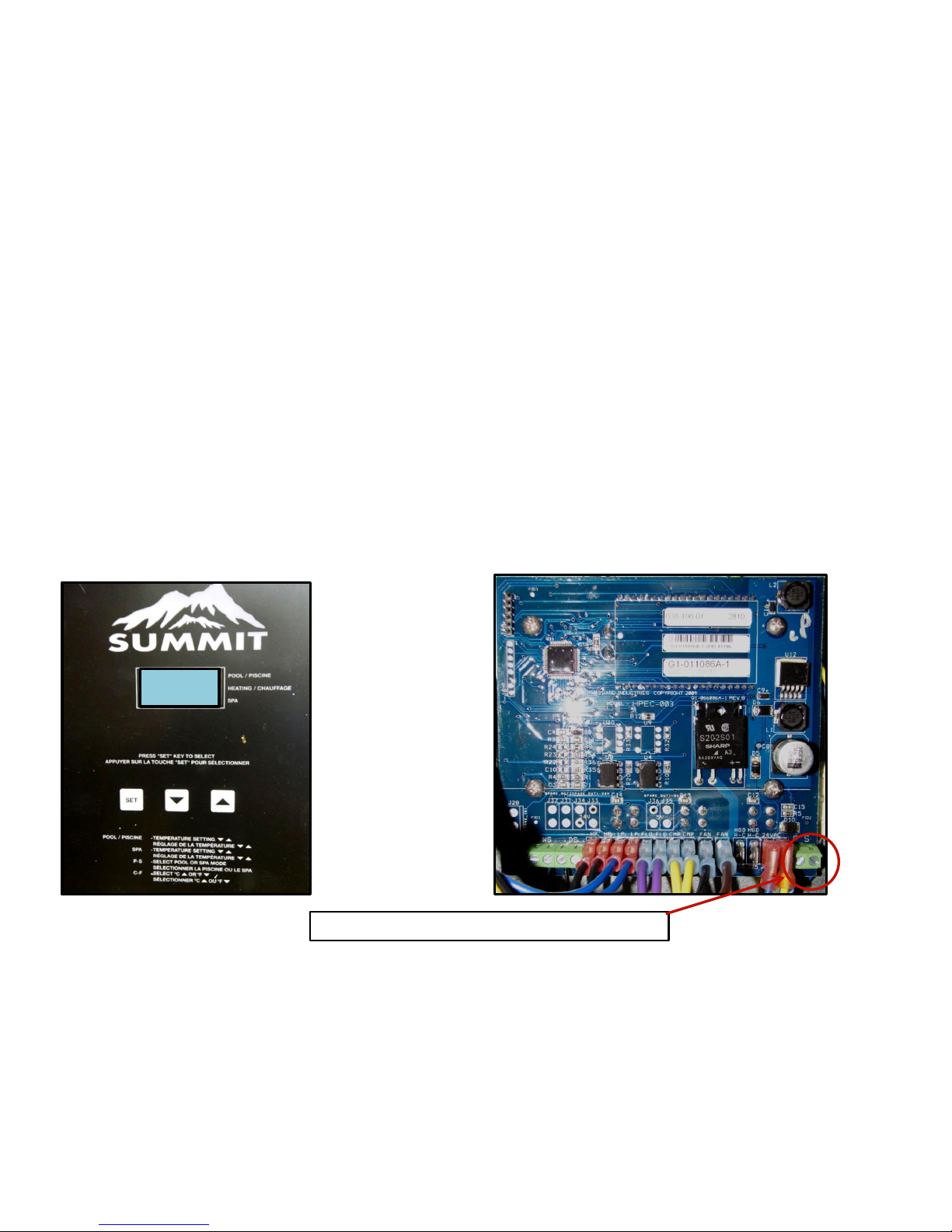
Setting Heat Pumps for Remote Operation
Summit Platform Heat Pumps
Attach 2 wires from remote to terminals marked ‘P’ and ‘S’ on the lower right corner of the control board.
Set Pool temperature to off. Set Spa temperature to ‘104’. Press and hold ‘Set/Select’ button until ‘Loc’
appears. Release the ‘Set/Select’ button. Press up arrow until 50 appears. This unlocks the set up menu.
Release up arrow. Press and release ‘Set/Select’ button 5 times or until ‘P_S’ appears.
Press up or down arrow until ‘E’ appears. Heat pump is now ready for remote operation.
Note: Move quickly between steps, if the temperature shows on display you will have to start over.
Loc
Attach 2 wires from remote to terminals P and S
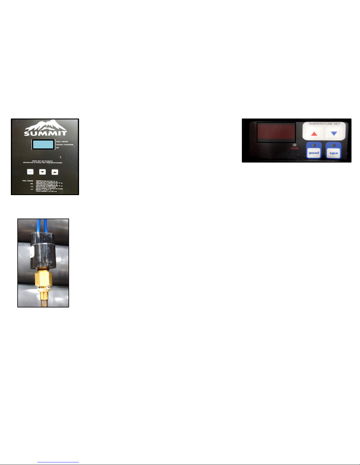
Common Error Codes
LP
LP
HeatPro Display
Summit Display
LP on Display
LP is an indication the low pressure switch is open. The
switch opens when the refrigerant pressure drops below
80PSI, and will automatically reset at 120PSI.
Sustained ambient temperatures below 21⁰F will cause the LP
error, however once the ambient temperature rises above
40⁰F the switch will close automatically.
Troubleshooting LP
The most common cause of LP on display is a loss of refrigerant pressure from a leak in the
refrigeration system. If refrigerant pressure is below 80PSI at your access port there has been a
significant loss of charge. Thoroughly leak check the system with an electronic leak detector, or
alternatively pressurize the system with dry
nitrogen and use a liquid leak detector such as “Big Blue”. If a leak still cannot be located inject UV
dye into the system and recharge to full charge. Allow several days to as long as several leaks
weeks -depending on apparent
severity of leak-, with normal heat pump operation for the dye to leak out with the refrigerant, and
return with UV light to determine leak location.
Once leak is located: Repair leak, evacuate system to a minimum 500 micron vacuum, and
recharge to factory charge (on data plate)
Other causes of LP error code
An intermittent LP code can be caused by a bad fan motor or capacitor. Check capacitor and
motor.
Bad LP switch. Check refrigerant pressure at access port. If pressure is above 120PSI check the
continuity of LP switch. Switch should be closed. If open replace switch. The LP switch is a screw
on style and does not require removing refrigerant charge to change. Be sure to use a thread
sealant when installing new switch. Always use a back up wrench when installing new pressure
switch.
If switch is closed, but LP is displayed check wires to switch for breaks. If no breaks are found
replace control board.
LP Switch
Note blue wires.
LP switch common to all
R-410A heat pumps
 Loading...