

Hayward SP3005X7, SP3005X7AZ, SP3007X10, SP3007X10EE, SP3007X10EEAZ Owner's Manual
...
P/N: IS3000XAZ-05
Rev. C
__________________________________________________________________________________________
OWNER’S MANUAL
INSTALLATION, OPERATION, & PARTS
Super II
The Hayward Super II Pump is specifically engineered for the demanding requirements of today’s in-ground swimming pool/spa that
is equipped with large capacity filters, heaters, and pool cleaning equipment. The Super II is a self-priming pump that incorporates an
improved seal and impeller design that will provide many years of efficient, dependable, corrosion-free service. The advanced design
provides superior performance while reducing maintenance requirements.
To prevent potential injury and to avoid unnecessary service calls, read this manual carefully and completely.
™
Pump Series
*50HZ Models are not UL or CSA Listed.
WARNING – This product should be installed and serviced only by a qualified professional.
CAUTION – A licensed electrician MUST complete, in full, all electrical installations noted in this manual.
SAVE THIS INSTRUCTION MANUAL
Use of non-Hayward replacement parts voids warranty.
ATTENTION
INSTALLATION,
OF THIS PRODUCT. FAILURE TO READ AND FOLLOW ALL INSTRUCTIONS COULD RESULT IN SERIOUS
INJURY.
INSTALLER – THIS MANUAL CONTAINS IMPORTANT INFORMATION ABOUT THE
OPERATION, AND SAFE USE OF THIS PUMP THAT MUST BE FURNISHED TO THE END USER
HAYWARD POOL PRODUCTS, INC.
620 DIVISION STREET ELIZABETH, NJ 07207 (908) 351-5400
WWW.HAYWARDPOOL.COM USE ONLY HAYWARD GENUINE REPLACEMENT PARTS
WWW.HAYWARDPOOL.COM
Super II™ Pump Series ____________________ ___________________________ Page 2 of 14
WARNING – Read and follow all instructions in this
owner’s manual and on the equipment. Failure to follow
instructions can cause severe injury and/or death.
IMPORTANT SAFETY INSTRUCTIONS
Basic safety precautions should always be followed, including the following: Failure to follow instructions may result in injury.
This is the safety-alert symbol. When you see this symbol on your pump or in this manual, look for one of the following
signal words and be alert to the potential for personal injury.
DANGER warns about hazards that will cause serious personal injury, death or major property damage and if
ignored presents an imminent hazard.
WARNING warns about hazards that could cause serious personal injury, death or major property damage and if
ignored presents a potential hazard.
CAUTION warns about hazards that will or can cause minor or moderate personal injury and/or property damage
and if ignored presents a potential hazard. It can also make consumers aware of actions that are unpredictable and unsafe.
The NOTICE label indicates special instructions that are important but not related to hazards.
Before installing or servicing this electrical equipment, turn power supply OFF.
WARNING – To reduce risk of injury, do not permit children to use or climb on this product. Closely supervise children
at all times. Components such as the filtration system, pumps, and heaters must be positioned to prevent children from using them as a
means of access to the pool.
CAUTION – This pump is intended for use on permanently installed swimming pools and may also be used with hot tubs
and spas if so marked. Do NOT use with storable pools. A permanently installed pool is constructed in or on the ground or in a
building such that it cannot be readily disassembled for storage. A storable pool is constructed so that it is capable of being readily
disassembled for storage and reassembled to its original integrity.
Though this product is designed for outdoor use, it is strongly advised to protect the electrical components from the weather. Select a
well-drained area, one that will not flood when it rains. It requires free circulation of air for cooling. Do not install in a damp or nonventilated location. If installed within an outer enclosure or beneath the skirt of a hot tub or spa, adequate ventilation and free circulation
of air must be provided to prevent overheating of the motor.
WARNING – Pool and spa components have a finite life. All components should be inspected frequently and replaced at
least every ten years, or if found to be damaged, broken, cracked, missing, or not securely attached.
WWW.HAYWARDPOOL.COM USE ONLY HAYWARD GENUINE REPLACEMENT PARTS
Super II™ Pump Series __________ _____ __________________________Page 3 of 14
WARNING – Risk of Electric Shock. Hazardous voltage. Can shock, burn, or cause
death. To reduce the risk of electric shock, do NOT use an extension cord to connect unit to electric
supply. Provide a properly located outlet. It is required that licensed electricians do all electrical wiring.
All electrical wiring MUST be in conformance with applicable local and national codes and regulations.
Before working on pump or motor, disconnect motor wiring.
WARNING – To reduce the risk of electric shock replace damaged cord immediately. Do NOT bury cord. Locate cord to
prevent abuse from lawn mowers, hedge trimmers and other equipment.
WARNING – Connect only to a grounding type receptacle protected by a Ground Fault Circuit Interrupter (GFCI).
Contact a licensed electrician if you cannot verify that the receptacle is protected by a GFCI.
WARNING – Failure to bond pump to pool structure will increase risk for electrocution and could result in injury or
death. To reduce the risk of electric shock, see installation instructions and consult a professional electrician on how to bond pump.
Also, contact a licensed electrician for information on local electrical codes for bonding requirements.
Use a solid copper conductor, size 8 or larger. Run a continuous wire from external bonding lug to reinforcing rod or mesh. Connect
a No. 8 AWG (8.4 mm
parts of swimming pool, spa, or hot tub, and to all electrical equipment, metal piping (except gas piping), and conduit within 5 ft. (1.5
m) of inside walls of swimming pool, spa, or hot tub. IMPORTANT - Reference NEC codes for all wiring standards including, but
not limited to, grounding, bonding and other general wiring procedures. NOTE - The National Electrical Code (NEC) permits use of
a cord with a maximum 3 ft. (1 m) length. If your pump is equipped with a cord complying with the NEC, the preceding four (4)
hazards apply.
2
) solid copper bonding wire to the pressure wire connector provided on the motor housing and to all metal
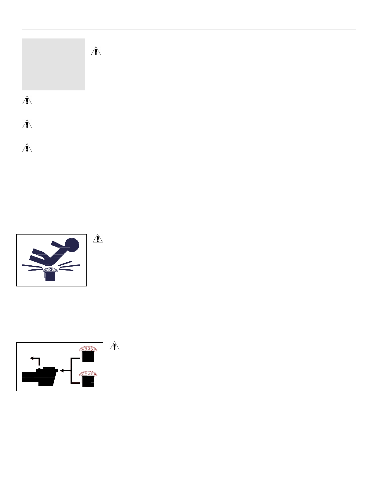
WARNING – Suction Entrapment Hazard.
Suction in suction outlets and/or suction outlet covers, which are damaged, broken, cracked, missing, or
unsecured cause severe injury and/or death due to the following entrapment hazards:
Hair Entrapment- Hair can become entangled in suction outlet cover.
Limb Entrapment- A limb inserted into an opening of a suction outlet sump or suction outlet cover that
is damaged, broken, cracked, missing, or not securely attached can result in a mechanical bind or
swelling of the limb.
Body Suction Entrapment- A pressure applied to a large portion of the body or limbs can result in an entrapment.
Evisceration/ Disembowelment- A negative pressure applied directly to the intestines through an unprotected suction outlet
sump or suction outlet cover which is damaged, broken, cracked, missing, or unsecured can result in
evisceration/disembowelment.
Mechanical Entrapment- There is potential for jewelry, swimsuits, hair decorations, fingers, toes, or knuckles to be caught
in an opening of a suction outlet cover resulting in mechanical entrapment.
WARNING - To Reduce the risk of Entrapment Hazards:
- When outlets are small enough to be blocked by a person, a minimum of two functioning suction
outlets per pump must be installed. Suction outlets in the same plane (i.e. floor or wall), must be
installed a minimum of three feet (3’) [0.91 meter] apart, as measured from near point to near
point.
- Dual suction fittings shall be placed in such locations and distances to avoid “dual blockage” by
a user.
- Dual suction fittings shall not be located on seating areas or on the backrest for such seating areas.
- The maximum system flow rate shall not exceed the values shown in the “Pipe Sizing Chart” found at the bottom of page 5
of this manual.
- Never use pool or spa if any suction outlet component is damaged, broken, cracked, missing, or not securely attached.
- Replace damaged, broken, cracked, missing, or not securely attached suction outlet components immediately.
- In addition to two or more suction outlets per pump installed in accordance with latest IAF (formerly NSPI) standards and
CPSC guidelines, follow all national, state, and local codes applicable.
- Installation of a vacuum release or vent system, which relieves entrapping suction, is recommended.
WWW.HAYWARDPOOL.COM USE ONLY HAYWARD GENUINE REPLACEMENT PARTS

Super II™ Pump Series __________ _____ ________________________ Page 4 of 14
WARNING – Hazardous Pressure. Pool and spa water circulation systems operate under
hazardous pressure during start-up, normal operation, and after pump shut-off. Stand clear of circulation
system equipment during pump start-up. Failure to follow safety and operation instructions could result in
violent separation of the pump housing and cover due to pressure in the system, which could cause property
damage, severe personal injury, or death. Before servicing pool and spa water circulation system, all
system and pump controls must be in off position and filter manual air relief valve must be in open
position. Before starting system pump, all system valves must be set in a position to allow system water to
return back to the pool. Do not change filter control valve position while system pump is running. Before
starting system pump, fully open filter manual air relief valve. Do not close filter manual air relief valve until a steady stream of water
(not air or air and water) is discharged. All suction and discharge valves MUST be OPEN when starting the circulation system.
Failure to do so could result in severe personal injury and/or property damage.
WARNING – Separation Hazard. Failure to follow safety and operation instructions could
result in violent separation of pump components. Strainer cover must be properly secured to pump housing
with strainer cover lock ring. Before servicing pool and spa circulation system, all system and pump
controls must be in off position and filter manual air relief valve must be in open position. Do not operate
pool and spa circulation system if a system component is not assembled properly, damaged, or missing. Do
not operate pool and spa circulation system unless filter air relief valve body is in locked position in filter
upper body. All suction and discharge valves MUST be OPEN when starting the circulation system.
Failure to do so could result in severe personal injury and/or property damage.
WARNING – Never operate or test the circulation system at more than 40 PSI.
WARNING – Fire and burn hazard. Motors operate at high temperatures and if they are not properly isolated from
any flammable structures or foreign debris they can cause fires, which may cause severe personal injury or death. It is also necessary
to allow the motor to cool for at least 20 minutes prior to maintenance to minimize the risk for burns.
WARNING – Failure to install according to defined instructions may result in severe personal injury or death.
General Information
Introduction
This manual contains information for the proper installation and operation of the Hayward Super II Pump Series. The
instructions in this manual MUST be followed precisely. Failure to install according to defined instructions will void
warranty.
Product Benefits
Super-sized 180 cubic-inch basket has extra leaf-holding capacity and extends time between cleanings. Rigid
construction with load extender ribbing assures free flowing operation for heavy debris loads.
Easy-Thread design makes strainer cover removal easy. No tools required, no loose parts, and no clamps.
Lexan see-thru strainer cover lets you see when the basket needs cleaning. Test feature allows line pressure test to 40
PSI MAXIMUM.
All components molded of corrosion-proof glass-filled polypropylene for extra durability and long life.
Heavy-duty, high-performance motor with airflow ventilation for quieter, cooler operation.
Uni-bracket mounting base provides stable, stress-free support, plus versatility for any installation requirement. Adapts
to 48 and 56 frame motors.
Heat resistant, industrial size ceramic seal.
Rugged, one-piece housing, with full-flow ports, assures rapid priming and continuous operation.
Totally balanced, Noryl high-head impeller provides high-volume output to accommodate even the most demanding
installations, including pool/spa combinations and in-floor cleaning systems.
Service-ease design gives simple access to all internal parts. Motor and entire drive group assembly can be removed,
without disturbing pipe or mounting connections, by disengaging just six (6) bolts.
WWW.HAYWARDPOOL.COM USE ONLY HAYWARD GENUINE REPLACEMENT PARTS
Super II™ Pump Series__________ _____ ______________________________Page 5 of 14
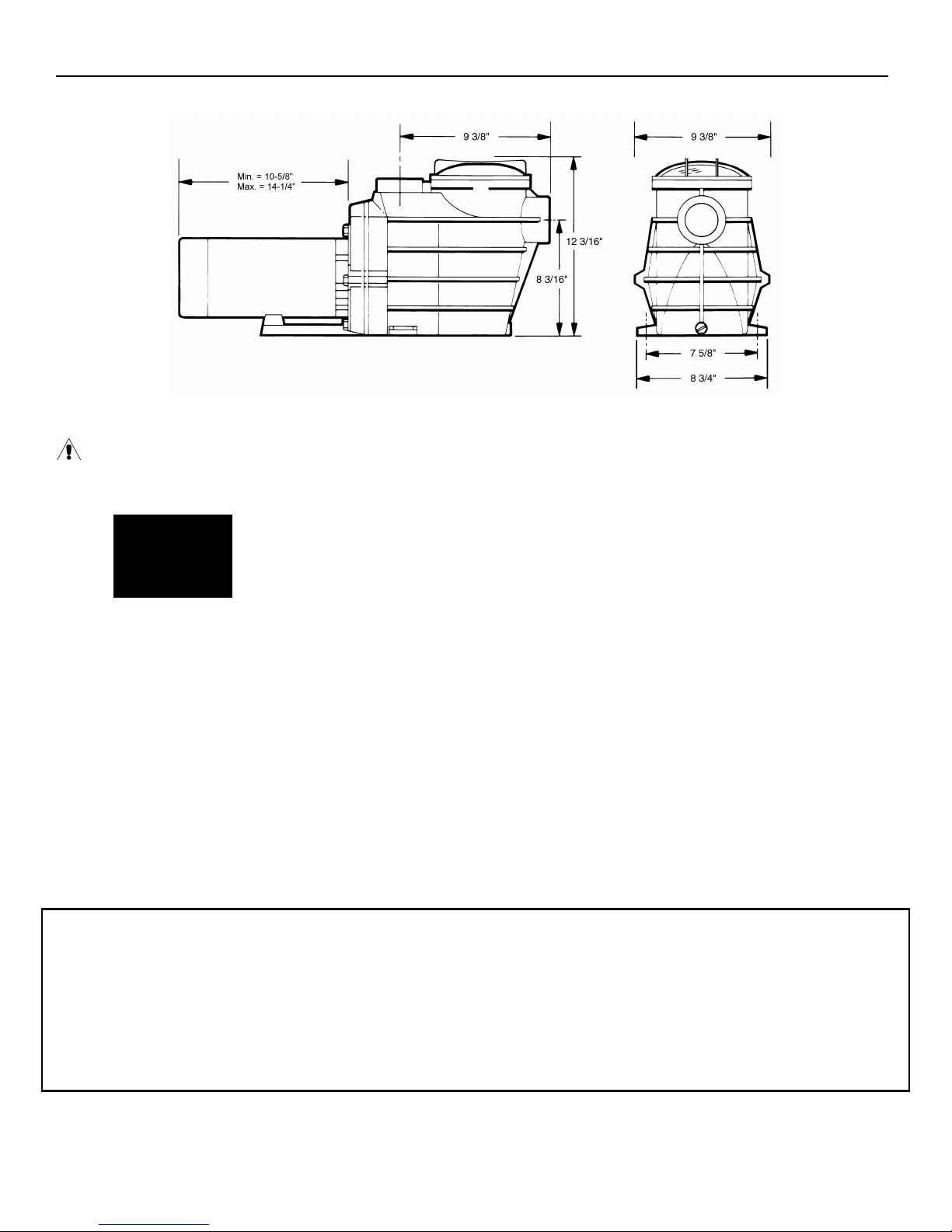
Product Specifications
Installation Instructions
WARNING – This product should be installed and serviced only by a qualified professional.
Pump Location
Locate pump as close to pool as practical and run suction lines as direct as possible to reduce friction
loss. Suction lines should have continuous slope upward from lowest point in line. Joints must be tight
(but not over-tightened). Suction line diameter must equal or be larger than the discharge line diameter.
Though the pump is designed for outdoor use, it is strongly advised to protect the electrical components
from the weather. Select a well-drained area, one that will not flood when it rains. Do NOT install pump in a damp or
non-ventilated location. Keep motor clean. Pump motors require free circulation of air for cooling.
Pump Mounting
Install pump on a firm, level base or pad to meet all local and national codes. Fasten pump to base or pad with screws or
bolts to further reduce vibration and stress on pipe or hose joints. The base MUST be solid, level, rigid, and vibration free.
Pump mount must:
Allow pump inlet height to be as close to water level as possible.
Allow use of short, direct suction pipe (to reduce friction losses).
Allow for gate valves in suction and discharge piping.
Be protected from excess moisture and flooding.
Pipe Sizing Chart
Allow adequate access for servicing pump and piping.
MAXIMUM RECOMMENDED SYSTEM FLOW RATE BY PIPE SIZE
Pipe Size
[mm]
1”
[32]
1 ¼”
[40]
WWW.HAYWARDPOOL.COM USE ONLY HAYWARD GENUINE REPLACEMENT PARTS
Flow rate
GPM [Liter/Min]
20
[75]
30
[110]
NOTE - It is recommended that a minimum length of piping, equivalent to 10 pipe diameters, be used between the
pump suction inlet and any plumbing fittings.
Pipe Size
[mm]
1 ½”
[50]
2”
[63]
Flow rate
GPM [Liter/Min]
45
[170]
80
[300]
Pipe Size
[mm]
2 ½”
[75]
3”
[90]
Flow rate
GPM [Liter/Min]
110
[415]
160
[600]
 Loading...