

Hayward SP2805X7, SP2807X10, SP2810X15, SP2815X20, SP2810X152 Owner's Manual
P/N: IS2800X5
Hayward Pool Products
Rev. C
__________________________________________________________________________________________
OWNER’S MANUAL
INSTALLATION, OPERATION, & PARTS
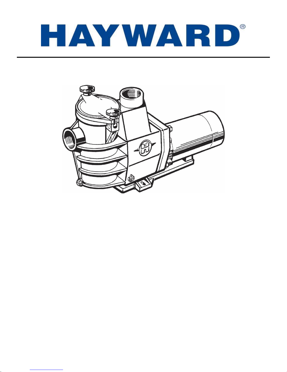
Max-Flo
The Hayward Max-Flo™ is specifically engineered for the demanding requirements of today’s in-ground swimming pool/spa that is
equipped with large capacity filters, heaters, and pool cleaning equipment. The Max-Flo™ is a self-priming pump that incorporates
an improved seal and impeller design that will provide many years of efficient, dependable, corrosion-free service. The advanced
design provides superior performance while reducing maintenance requirements.
™
PUMP Series
620 Division Street, Elizabeth, NJ 07207
Phone: (908) 351.5400
www.haywardnet.com
Basic safety precautions should always be followed, including the following: Failure to follow instructions can cause
IMPORTANT SAFETY INSTRUCTIONS
severe injury and/or death.
This is the safety-alert symbol. When you see this symbol on your equipment or in this manual, look for one of
the following signal words and be alert to the potential for personal injury.
WARNING warns about hazards that could cause serious personal injury, death or major property damage and
if ignored presents a potential hazard.
CAUTION warns about hazards that will or can cause minor or moderate personal injury and/or property
damage and if ignored presents a potential hazard. It can also make consumers aware of actions that are
unpredictable and unsafe.
The NOTICE label indicates special instructions that are important but not related to hazards.
WARNING – READ AND FOLLOW ALL INSTRUCTIONS
in this owner’s manual and on the equipment. Failure to follow instructions can cause severe injury and/or death.
WARNING – Suction Entrapment Hazard.
Suction in suction outlets and/or suction outlet covers which are, damaged, broken, cracked, missing, or unsecured can cause severe injury
and/or death due to the following entrapment hazards:
Hair Entrapment- Hair can become entangled in suction outlet cover.
Limb Entrapment- A limb inserted into an opening of a suction outlet sump or suction outlet cover that is damaged, broken, cracked,
missing, or not securely attached can result in a mechanical bind or swelling of the limb.
Body Suction Entrapment- A negative pressure applied to a large portion of the body or limbs can result in an entrapment.
Evisceration/ Disembowelment - A negative pressure applied directly to the intestines through an unprotected suction outlet sump or
suction outlet cover which is, damaged, broken, cracked, missing, or unsecured can result in evisceration/ disembowelment.
Mechanical Entrapment- There is potential for jewelry, swimsuit, hair decorations, finger, toe or knuckle to be caught in an opening of a
suction outlet cover resulting in mechanical entrapment.
WARNING - To Reduce the risk of Entrapment Hazards:
o When outlets are small enough to be blocked by a person, a minimum of two functioning suction outlets per pump must be
installed. Suction outlets in the same plane (i.e. floor or wall), must be installed a minimum of three feet (3’) [1 meter] apart, as
measured from near point to near point.
o Dual suction fittings shall be placed in such locations and distances to avoid “dual blockage” by a user.
o Dual suction fittings shall not be located on seating areas or on the backrest for such seating areas.
o The maximum system flow rate shall not exceed the flow rating of as listed on Table 1.
o Never use Pool or Spa if any suction outlet component is damaged, broken, cracked, missing, or not securely attached.
o Replace damaged, broken, cracked, missing, or not securely attached suction outlet components immediately.
o In addition two or more suction outlets per pump installed in accordance with latest ASME, APSP Standards and CPSC
guidelines, follow all National, State, and Local codes applicable.
o Installation of a vacuum release or vent system, which relieves entrapping suction, is recommended.
WARNING – Failure to remove pressure test plugs and/or plugs used in winterization of the pool/spa from the
suction outlets can result in an increase potential for suction entrapment as described above.
WARNING – Failure to keep suction outlet components clear of debris, such as leaves, dirt, hair, paper and
other material can result in an increase potential for suction entrapment as described above.
WARNING – Suction outlet components have a finite life, the cover/grate should be inspected frequently and
replaced at least every ten years or if found to be damaged, broken, cracked, missing, or not securely attached.
CAUTION – Components such as the filtration system, pumps and heater must be positioned so as to prevent
their being used as means of access to the pool by young children.
WARNING – Never operate or test the circulation system at more than 50 PSI.
WARNING – Never change the filter control valve position while the pump is running.
WARNING – To reduce risk of injury, do not permit children to use or climb on this product. Closely supervise children at all
times. Components such as the filtration system, pumps, and heaters must be positioned to prevent children from using them as a means of
access to the pool.
USE ONLY HAYWARD GENUINE REPLACEMENT PARTS
Page 2 of 16 Max-Flo™ PUMP Series IS2800X5 Rev. C
WARNING – Hazardous Pressure. Pool and spa water circulation systems operate under hazardous pressure during start up,
normal operation, and after pump shut off. Stand clear of circulation system equipment during pump start up. Failure to follow safety and
operation instructions could result in violent separation of the pump housing and cover, and/or filter housing and clamp due to pressure in
the system, which could cause property damage, severe personal injury, or death. Before servicing pool and spa water circulation system,
all system and pump controls must be in off position and filter manual air relief valve must be in open position. Before starting system
pump, all system valves must be set in a position to allow system water to return back to the pool. Do not change filter control valve
position while system pump is running. Before starting system pump, fully open filter manual air relief valve. Do not close filter manual
air relief valve until a steady stream of water (not air or air and water) is discharged.
WARNING – Separation Hazard. Failure to follow safety and operation instructions could result in violent separation of
pump and/or filter components. Strainer cover must be properly secured to pump housing with strainer cover lock ring. Before servicing
pool and spa circulation system, filters manual air relief valve must be in open position. Do not operate pool and spa circulation system if a
system component is not assembled properly, damaged, or missing. Do not operate pool and spa circulation system unless filter manual air
relief valve body is in locked position in filter upper body.
WARNING – Risk of Electric Shock. All electrical wiring MUST be in conformance with applicable local codes, regulations,
and the National Electric Code (NEC). Hazardous voltage can shock, burn, and cause death or serious property damage. To reduce the
risk of electric shock, do NOT use an extension cord to connect unit to electric supply. Provide a properly located electrical receptacle.
Before working on any electrical equipment, turn off power supply to the equipment.
WARNING – To reduce the risk of electric shock replace damaged wiring immediately. Locate conduit to prevent abuse from
lawn mowers, hedge trimmers and other equipment.
WARNING – Electrical ground all electrical equipment before connecting to electrical power supply. Failure to ground all
electrical equipment can cause serious or fatal electrical shock hazard.
WARNING – Do NOT ground to a gas supply line.
WARNING – To avoid dangerous or fatal electrical shock, turn OFF power to all electrical equipment before working on
electrical connections.
WARNING – Failure to bond all electrical equipment to pool structure will increase risk for electrocution and could result in
injury or death. To reduce the risk of electric shock, see installation instructions and consult a professional electrician on how to bond all
electrical equipment. Also, contact a licensed electrician for information on local electrical codes for bonding requirements.
Notes to electrician: Use a solid copper conductor, size 8 or larger. Run a continuous wire from external bonding lug to reinforcing rod
or mesh. Connect a No. 8 AWG (8.4 mm2) [No. 6 AWG (13.3 mm2) for Canada] solid copper bonding wire to the pressure wire connector
provided on the electrical equipment and to all metal parts of swimming pool, spa, or hot tub, and metal piping (except gas piping), and
conduit within 5 ft. (1.5 m) of inside walls of swimming pool, spa, or hot tub.
IMPORTANT - Reference NEC codes for all wiring standards including, but not limited to, grounding, bonding and other general wiring
procedures.
WARNING – Risk of Electric Shock. Connect only to a branch circuit protected by a ground-fault circuit-interrupter (GFCI).
Contact a qualified electrician if you cannot verify that the circuit is protected by a GFCI.
WARNING – Risk of Electric Shock . The electrical equipment must be connected only to a supply circuit that is protected by a
ground-fault circuit-interrupter (GFCI). Such a GFCI should be provided by the installer and should be tested on a routine basis. To test
the GFCI, push the test button. The GFCI should interrupt power. Push reset button. Power should be restored. If the GFCI fails to
operate in this manner, the GFCI is defective. If the GFCI interrupts power to the electrical equipment without the test button being
pushed, a ground current is flowing, indicating the possibility of an electrical shock. Do not use this electrical equipment. Disconnect the
electrical equipment and have the problem corrected by a qualified service representative before using.
CAUTION – This pump is intended for use with permanently-installed pools and may be used with hot tubs and spas if so
marked. Do not use with storable pools. A permanently-installed pool is constructed in or on the ground or in a building such that it
cannot be readily disassembled for storage. A storable pool is constructed so that it is capable of being readily disassembled for storage
and reassembled to its original integrity.
SAVE THESE INSTRUCTIONS
USE ONLY HAYWARD GENUINE REPLACEMENT PARTS
Page 3 of 16 Max-Flo™ PUMP Series IS2800X5 Rev. C
General Information
Introduction
This manual contains information for the proper installation and operation of the Hayward Max-Flo™ Series. The
instructions in this manual MUST be followed precisely. Failure to install according to defined instructions will void
warranty.
Product Benefits
Exclusive swing-aside knobs make strainer cover removal easy.
See-thru strainer cover lets you see when the basket needs cleaning.
Strainer basket incorporates an integral an integral handle for easy removal. Load extender ribbing ensures free flowing
operations.
Heavy-duty, high performance motor for quieter, cooler operation.
Service-ease design gives simple access to all internal parts.
Self-priming (suction lift up to 8’ above water level)
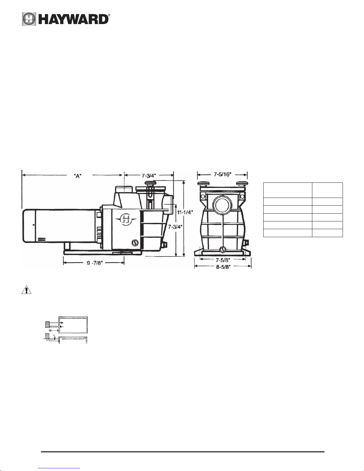
Product Specifications
Installation Instructions
WARNING – This product should be installed and serviced only by a qualified professional.
Pump Location
Locate pump as close to pool as practical and run suction lines as direct as possible to reduce friction
loss. Suction lines should have continuous slope upward from lowest point in line. Joints must be tight
(but not over-tightened). Suction line diameter must equal or be larger than the discharge line diameter.
Though the pump is designed for outdoor use, it is strongly advised to protect the electrical components
from the weather. Select a well-drained area, one that will not flood when it rains. Do NOT install pump in a damp or
non-ventilated location. Keep motor clean. Pump motors require free circulation of air for cooling.
Pump Mounting
Install pump on a firm, level base or pad to meet all local and national codes. Fasten pump to base or pad with screws or
bolts to further reduce vibration and stress on pipe or hose joints. The base MUST be solid, level, rigid, and vibration free.
Pump mount must:
Allow pump inlet height to be as close to water level as possible.
Allow use of short, direct suction pipe (to reduce friction losses).
Allow for gate valves in suction and discharge piping.
Be protected from excess moisture and flooding.
PUMP PART
NUMBER
SP2805X7
SP2807X10
SP2810X15
SP2815X20
SP2810X152
LENGTH
“A”
14"
14-3/8"
15-1/2"
16"
13-7/8"
USE ONLY HAYWARD GENUINE REPLACEMENT PARTS
Page 4 of 16 Max-Flo™ PUMP Series IS2800X5 Rev. C
Allow adequate access for servicing pump and piping.
Incorporate a straight portion of pipe prior to pump inlet no less than (5) pipe diameters in length.
Pipe Sizing Chart
MAXIMUM RECOMMENDED SYSTEM FLOW RATE BY PIPE SIZE
Pipe Size Flow rate Water Velocity Pipe Size Flow rate Water Velocity
inches [mm] GPM [Liter/Min] ft/sec [meters/sec] inches [mm] GPM [Liter/Min] ft/sec [meters/sec]
1 ½” 50.76 8 2 ½” 119.40 8
[50] [192] [2.44] [75] [452] [2.44]
2” 83.65 8 3” 184.32 8
[63] [317] [2.44] [90] [698] [2.44]
NOTE – No system should allow any higher than 8-ft/sec [2.44 meters/sec] water velocity. It is recommended that a minimum
length of piping, equivalent to 10 pipe diameters, be used between the pump suction inlet and any plumbing fittings.
WARNING – Hazardous Pressure. Pumps, filters, and other equipment/ components of a
swimming pool filtration system operate under pressure. Incorrectly installed and/or improperly tested
filtration equipment and/or components may fail resulting in injury and/or property damage.
Plumbing
Use Teflon tape to seal threaded connections on molded plastic components. All plastic fittings must be new or thoroughly
cleaned before use. NOTE - Do NOT use Plumber’s Pipe Dope as it may cause cracking of the plastic components.
When applying Teflon tape to plastic threads, wrap the entire threaded portion of the male fitting with one to two layers of
tape. Wind the tape clockwise as you face the open end of the fitting, beginning at the end of the fitting. The pump suction
and outlet ports have molded-in thread stops. Do NOT attempt to force hose connector fitting past this stop. It is only
necessary to tighten fittings enough to prevent leakage. Tighten fitting by hand and then use a tool to engage fitting an
additional 1 ½ turns. Use care when using Teflon tape as friction is reduced considerably; do NOT over-tighten fitting or
you may cause damage. If leaks occur, remove connector, clean off old Teflon tape, re-wrap with one to two additional
layers of Teflon tape, and re-install connector.
Fittings
Fittings restrict flow. For better efficiency, use the fewest possible fittings (but at least two suction outlets). Avoid fittings
that could cause an air trap. Pool and spa fittings MUST conform to the International Association of Plumbing and
Mechanical Officials (IAPMO) standards. Use a non-entrapping suction fitting in pool (multiple drains) or double suction
(skimmer and main drain).
Electrical
WARNING – All wiring must be done by a licensed electrician and must conform to all
local and national codes and regulations.
WARNING – Ground and bond motor before connecting to electrical power supply. Failure
to ground and bond pump motor can cause serious or fatal electrical shock hazard.
WARNING – Do NOT ground to a gas supply line.
WARNING – To avoid dangerous or fatal electrical shock, turn OFF power to motor before
working on electrical connections.
WARNING – Ground Fault Circuit Interrupter (GFCI) tripping indicates electrical problem. If GFCI trips and
won’t reset, consult electrician to inspect and repair electrical system.
WARNING – Fire Hazard. Match supply voltage to motor nameplate voltage.
USE ONLY HAYWARD GENUINE REPLACEMENT PARTS
Page 5 of 16 Max-Flo™ PUMP Series IS2800X5 Rev. C
 Loading...