

Hayward SP2305X7, SP2305X7EE, SP2305X7EESP, SP2307X10, SP2310X15 Owner's Manual
...
g
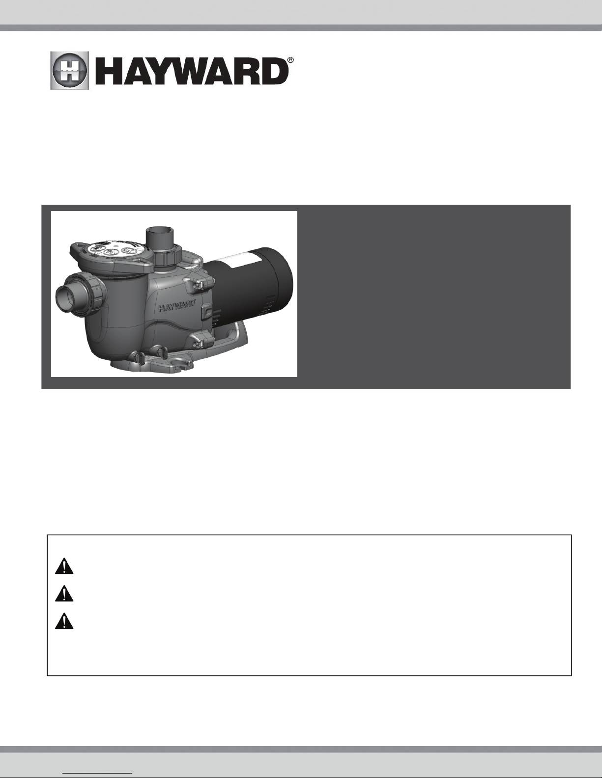
MaxFlo XL
IS2300 Rev D
™
Pump Series
Owner’s Manual
Contents
Full Table of Contents……..…..…2
General Product Warnings…….…3
Installation and Wiring……..….…5
Start up and Operation…………..9
Shaft Seal Replacement………...10
Replacement Parts………..…….…13
Warrantee…………………….…..……15
Re
istration………………….………..16
IMPORTANT SAFETY INSTRUCTIONS
The Hayward MaxFlo XL is a series of high technology self-priming pumps that combine
performance, dependability and value with durable construction. Designed for pools of all types
and sizes, MaxFlo XL features 1 1/2” x 2” union connections to match a variety of plumbing
configurations and a cam and ramp strainer cover that seals with less than a quarter turn. The
MaxFlo XL is an ideal choice for both new construction or as a replacement pump.
Basic safety precautions should always be followed, including the following: Failure to follow
instructions can cause severe injury and/or death.
This is the safety-alert symbol. When you see this symbol on your equipment or in this manual, look for
one of the following signal words and be alert to the potential for personal injury.
WARNING warns about hazards that could cause serious personal injury, death or major property
damage and if ignored presents a potential hazard.
CAUTION warns about hazards that will or can cause minor or moderate personal injury and/or property
damage and if ignored presents a potential hazard. It can also make consumers aware of actions that are
unpredictable and unsafe.
The NOTICE label indicates special instructions that are important but not related to hazards.
USE ONLY HAYWARD GENUINE REPLACEMENT PARTS 1
Hayward Pool Products
620 Division Street, Elizabeth, NJ 07207
Phone: (908) 355-7995
www.hayward.com

Table of Contents
1. IMPORTANT SAFETY INSTRUCTIONS ................................................................................................................. 3
2. General Information ........................................................................................................................................ 5
2.1. Introduction 5
2.2. Primary Features 5
2.3. Product Dimensions 5
3. Installation and Wiring .................................................................................................................................... 5
3.1. Pump Location 5
3.2. Pump Mounting 6
3.3. Pipe Sizing Chart 6
3.4. Plumbing 6
3.5. Electrical 6
3.6. Electrical Specs 7
3.7. Voltage 7
3.8. Grounding and Bonding 7
3.9. Wiring 7
4. Startup & Operation ........................................................................................................................................ 8
4.1. Prior to Start-Up 8
4.2. Starting/Priming the Pump 9
5. Maintenance .................................................................................................................................................. 9
6. Storage / Winterization ................................................................................................................................... 9
6.1. Storing Pump For Winterization 10
7. Shaft Seal Change Instructions ..................................................................................................................... 10
7.1. Removing the Motor Assembly 10
7.2. Removing the Impeller 10
7.3. Removing the Ceramic Seat 10
7.4. Seal Installation 11
7.5. Replacing the Impeller and Diffuser 12
7.6. Replacing the Motor Assembly 12
8. Replacement Parts ........................................................................................................................................ 13
8.1. Parts Diagram 13
8.2. Parts Listing 13
9. Troubleshooting ........................................................................................................................................... 14
9.1. General Problems 14
10. Warranty ....................................................................................................................................................... 15
11. Product Registration ..................................................................................................................................... 15
USE ONLY HAYWARD GENUINE REPLACEMENT PARTS 2
S
A
f
N
e
a
t
u
e
N
Wbeap
h
e
ngu
n
N
u
N
a
N
a
T
d
N
o
p
e
g
N
/
n
m
E
/
a
b
e
w
v
a
e
e
c
r
i
i
y
o
e
o
w
v
e
e
o
o
d
s
d
n
o
e
a
c
e
r
o
o
s
O
T
,
e
e
l
a
a
e
e
a
t
e
n
o
p
c
c
e
r
s
e
p
s
r
g
r
m
t
d
m
n
I
i
e
W
N
y
s
o
a
r
n
y
a
n
o
e
e
m
o
m
a
m
u
o
m
o
a
.
e
p
a
c
p
a
e
a
b
e
r
o
I
h
d
.
t
b
o
c
m
w
s
n
m
a
e
u
a
r
t
e
p
r
s
t
a
c
t
m
m
t
v
d
d
w
t
C
n
k
o
g
u
i
s
o
o
i
s
s
c
s
m
n
o
m
r
p
e
r
o
p
i
e
e
R
o
r
n
a
k
s
a
i
i
E
.
d
p
o
e
h
u
u
t
o
s
r
a
D
o
g
y
a
e
n
n
a
f
u
i
r
f
n
a
o
e
s
f
e
m
o
t
k
p
n
t
e
t
e
o
s
r
d
1. I
MPORT
uction in sucti
njury and/or d
i
WAR
Failure to
WAR
Hair Entra
Limb Entr
cracked, m
Body Suc
Eviscerati
sump or s
disembow
Mechanic
opening of
WAR
o
o D
o D
o T
o N
o R
o I
o I
WAR
suction o
WAR
material c
WAR
replaced
CAU
being use
on this pro
positioned
NT SAF
NING – Read
ollow instruct
ING
– Sucti
on outlets and
ath due to the
pment
- Hair c
pment
- A lim
issing, or not s
ion Entrapm
on/ Disembo
ction outlet co
lment.
l Entrapmen
a suction outl
ING - To Red
hen outlets ar
installed. Su
art, as measu
ual suction fitt
ual suction fitt
e maximum s
ever use Pool
place damag
addition two
idelines, follo
stallation of a
ING –
Failur
tlets can resu
ING –
Failur
n result in an
ING –
Sucti
t least every s
ION –
Comp
as means of
uct. Closely
to prevent chil
TY INS
understand
ions can caus
on Entrapm
or suction out
following entr
n become ent
inserted into
ecurely attach
nt
- A negative
elment
er which is, d
- There is pot
t cover resulti
uce the risk
small enough
tion outlets in
ed from near
ngs shall be pl
ngs shall not b
stem flow rate
r Spa if any su
d, broken, cra
r more suction
all National,
acuum releas
to remove p
lt in an increa
to keep suct
increase pot
n outlet com
even years or
nents such a
access to the
upervise child
dren from usin
- A n
RUCTIO
, and follow
severe injur
nt Hazard.
et covers whic
pment hazard
ngled in sucti
an opening of
d can result in
pressure appli
gative pressu
maged, broke
ntial for jewelr
g in mechanic
f Entrapme
to be blocked
the same plan
oint to near po
aced in such l
e located on s
shall not exce
tion outlet co
ked, missing,
outlets per pu
State, and Loc
or vent syste
essure test pl
e potential f
ion outlet co
ntial for sucti
onents have
if found to be
the filtration
pool by young
en at all times
them as a m
S
ll instructio
and/or deat
h are, damage
:
n outlet cover
suction outle
a mechanical
d to a large p
e applied dire
, cracked, mis
, swimsuit, ha
l entrapment.
t Hazards:
by a person, a
e (i.e. floor or
int.
cations and di
ating areas or
d the flow rati
ponent is da
r not securely
p installed in
l codes applic
, which reliev
gs and/or pl
r suction entr
ponents clea
n entrapmen
finite life, th
damaged, bro
system, pum
children. To
Components
ans of access
ns
in this ow
.
, broken, crac
sump or sucti
ind or swellin
rtion of the bo
tly to the intes
sing, or unsec
ir decorations,
minimum of tw
all), must be i
stances to avo
on the backre
g of as listed
aged, broken,
attached sucti
accordance w
able.
s entrapping
gs used in wi
pment as de
of debris, su
as described
cover/grate
ken, cracked,
s and heater
educe risk of i
such as the filt
o the pool.
er’s manual a
ed, missing,
on outlet cove
of the limb.
dy or limbs ca
tines through
red can result
finger, toe or
o functioning
nstalled a mini
d “dual block
t for such seat
n Table 1.
cracked, miss
n outlet comp
th latest ASM
uction, is reco
nterization of
cribed above
h as leaves,
above.
hould be ins
missing, or n
ust be positi
jury, do not p
ration system,
nd on the equ
r unsecured c
that is damag
result in an e
n unprotected
in evisceratio
nuckle to be c
uction outlets
mum of three
ge” by a user.
ng areas.
ng, or not sec
onents immed
, APSP Standa
mmended.
the pool/spa
irt, hair, pape
ected freque
t securely att
oned so as to
rmit children t
pumps, and h
ipment.
n cause sever
d, broken,
trapment.
suction outlet
/
ught in an
per pump mus
eet (3’) [1 met
rely attached.
ately.
ds and CPSC
rom the
r and other
tly and
ched.
prevent their
use or climb
aters must be
r]
WAR
start up, n
follow safe
and clamp
pool and s
be in open
back to th
open filter
is dischar
WAR
pump and
servicing p
circulation
circulation
circulatio
air can cau
high volu
ING – Hazar
rmal operatio
ty and operati
due to pressur
a water circul
position. Befo
pool. Do not
manual air reli
ed.
ING – Sepa
or filter comp
ool and spa cir
system if a sys
system unless
system at m
se component
e blower when
ous Pressu
, and after pu
n instructions
in the system
tion system, a
re starting sys
hange filter co
f valve. Do no
ation Hazar
nents. Straine
culation syste
tem compone
filter manual a
re than 50 PS
to explode, w
air purging th
could result in
ll system and
em pump, all s
ntrol valve pos
t close filter m
r cover must b
ir relief valve b
USE
e.
Pool and s
p shut off. St
, which could
.
Failure to fol
, filters manu
t is not assem
. Do not purg
th risk of seve
pump, filter,
NLY HAY
a water circul
nd clear of cir
violent separa
ause property
ump controls
ystem valves
ition while sys
nual air relief
low safety and
properly secu
l air relief valv
led properly,
ody is in locke
the system
e injury or dea
r piping.
ARD GENU
tion systems
ulation syste
ion of the pum
damage, seve
ust be in off
ust be set in a
em pump is ru
alve until a st
operation inst
red to pump h
e must be in o
amaged, or m
position in fil
ith compress
h to anyone n
INE REPLA
perate under
equipment d
p housing and
e personal inj
osition and fil
position to all
nning. Before
ady stream of
uctions could
using with str
en position.
ssing. Do not
ter upper body
ed air. Purgin
arby. Use onl
EMENT PA
azardous pres
ring pump sta
cover, and/or
ry, or death. B
er manual air r
w system wat
tarting syste
water (not air
esult in violen
iner cover loc
o not operate
perate pool a
. Never opera
the system wi
a low pressur
TS
ure during
rt up. Failure t
ilter housing
efore servicing
elief valve mu
r to return
pump, fully
r air and wate
separation of
ring. Before
ool and spa
d spa
e or test the
th compresse
e (below 5 PSI)
3
t
)
WARNING – Risk of Electric Shock. All electrical wiring MUST be in conformance with applicable local codes, regulations,
and the National Electric Code (NEC). Hazardous voltage can shock, burn, and cause death or serious property damage. To
reduce the risk of electric shock, do NOT use an extension cord to connect unit to electric supply. Provide a properly located
electrical receptacle. Before working on any electrical equipment, turn off power supply to the equipment. To reduce the risk of
electric shock replace damaged wiring immediately. Locate conduit to prevent abuse from lawn mowers, hedge trimmers and
other equipment. Do NOT ground to a gas supply line.
WARNING – Risk of Electric Shock Failure to ground all electrical equipment can cause serious or fatal electrical shock
hazard. Electrical ground all electrical equipment before connecting to electrical power supply.
WARNING – Risk of Electric Shock Failure to bond all electrical equipment to pool structure will increase risk for
electrocution and could result in injury or death. To reduce the risk of electric shock, see installation instructions and consult a
professional electrician on how to bond all electrical equipment. Also, contact a licensed electrician for information on local
electrical codes for bonding requirements.
Notes to electrician: Use a solid copper conductor, size 8 or larger. Run a continuous wire from external bonding lug to
reinforcing rod or mesh. Connect a No. 8 AWG (8.4 mm
pressure wire connector provided on the electrical equipment and to all metal parts of swimming pool, spa, or hot tub, and metal
piping (except gas piping), and conduit within 5 ft. (1.5 m) of inside walls of swimming pool, spa, or hot tub.
IMPORTANT - Reference NEC codes for all wiring standards including, but not limited to, grounding, bonding and other general
wiring procedures.
2
) [No. 6 AWG (13.3 mm2) for Canada] solid copper bonding wire to the
WARNING – Risk of Electric Shock . The electrical equipment must be connected only to a supply circuit that is protected
by a ground-fault circuit-interrupter (GFCI). Such a GFCI should be provided by the installer and should be tested on a routine
basis. To test the GFCI, push the test button. The GFCI should interrupt power. Push reset button. Power should be restored. If
the GFCI fails to operate in this manner, the GFCI is defective. If the GFCI interrupts power to the electrical equipment without the
test button being pushed, a ground current is flowing, indicating the possibility of an electrical shock. Do not use this electrical
equipment. Disconnect the electrical equipment and have the problem corrected by a qualified service representative before
using.
CAUTION – HAYWARD
spas if so marked. Do not use with storable pools. A permanently-installed pool is constructed in or on the ground or in a
building such that it cannot be readily disassembled for storage. A storable pool is constructed so that it is capable of being
readily disassembled for storage and reassembled to its original integrity.
®
pumps are intended for use with permanently-installed pools and may be used with hot tubs and
WARNING – Risk of Hyperthermia. To avoid hyperthermia the following “Safety Rules for Hot Tubs” are recommended by
the U.S. Consumer Product Safety Commission.
1. Spa or hot tub water temperatures should never exceed 104°F [40°C]. A temperature of 100°F [38°C] is
considered safe for a healthy adult. Special caution is suggested for young children. Prolonged immersion in
hot water can induce hyperthermia.
2. Drinking of alcoholic beverages before or during spa or hot tub use can cause drowsiness, which
could lead to unconsciousness and subsequently result in drowning.
3. Pregnant women beware! Soaking in water above 100°F [38°C] can cause fetal damage during the
first three months of pregnancy (resulting in the birth of a brain-damaged or deformed child). Pregnant women
should adhere to the 100°F [38°C] maximum rule.
4. Before entering the spa or hot tub, users should check the water temperature with an accurate thermometer; spa or hot tub thermostats may err in regulating water temperatures by as much as 4°F (2.2°C).
5. Persons taking medications, which induce drowsiness, such as tranquilizers, antihistamines or anticoagulants, should not use spas or hot tubs.
6. If the pool/spa is used for therapy, it should be done with the advice of a physician. Always stir pool/ spa
water before entering the pool/spa to mix in any hot surface layer of water that might exceed healthful
temperature limits and cause injury. Do not tamper with controls, because scalding can result if safety controls
are not in proper working order.
7. Persons with a medical history of heart disease, circulatory problems, diabetes or blood pressure
problems should obtain a physicians’ advice before using spas or hot tubs.
8. Hyperthermia occurs when the internal temperature of the body reaches a level several degrees above
normal body temperature of 98.6°F [37°C]. The symptoms of Hyperthermia include: drowsiness, lethargy,
dizziness, fainting, and an increase in the internal temperature of the body.
The effects of Hyperthermia include:
1. Unawareness of impending danger.
2. Failure to perceive heat.
3. Failure to recognize the need to leave the spa.
4. Physical inability to exit the spa.
5. Fetal damage in pregnant women.
6. Unconsciousness resulting in danger of drowning.
USE ONLY HAYWARD GENUINE REPLACEMENT PARTS 4
SAVE THESE INSTRUCTIONS
2. General Information
2.1. Introduction
This manual contains information for the proper installation and operation of the Hayward MaxFlo XL Series. The
instructions in this manual MUST be followed precisely. Failure to install according to defined instructions will
void warranty.
2.2. Primary Features
• Aligns with the original MaxFlo pump for seamless retrofit installations.
• Advanced hydraulics for increased efficiency and priming ability.
• All models include 1 1/2” x 2” union connections.
• See-through strainer cover lets you see when the basket needs cleaning and seals with less than a quarter turn.
• Pressure testable to 50 psi maximum.
• Optional riser base available to align with Sta-Rite® Dyna-Pro®.
• Self-priming (suction lift up to 8’ above water level)
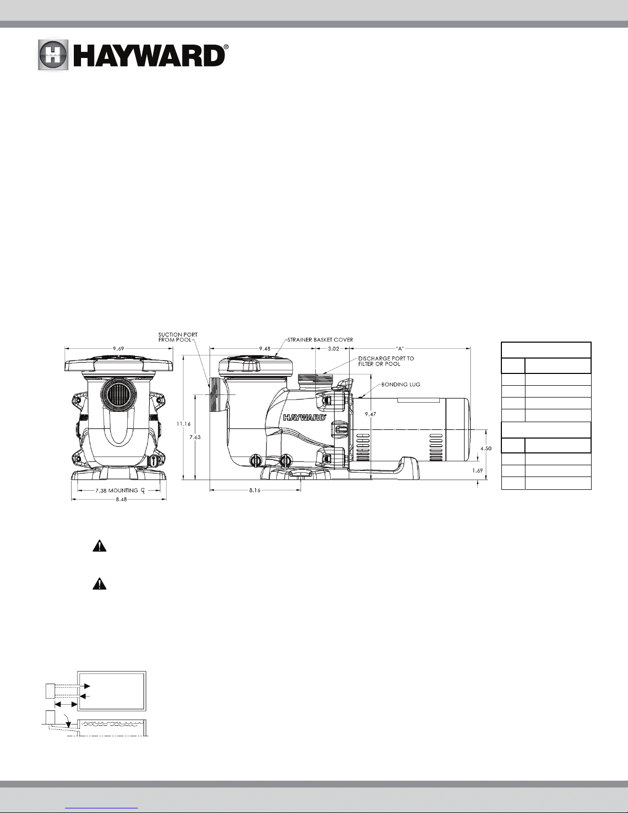
2.3. Product Dimensions
3. Installation and Wiring
WARNING – This product should be installed and serviced only by a qualified professional.
3.1. Pump Location
WARNING – Fire and burn hazard. Motors operate at high temperatures and if they are not
properly isolated from any flammable structures or foreign debris they can cause fires, which may cause
severe personal injury or death. It is also necessary to allow the motor to cool for at least 20 minutes prior
to maintenance to minimize the risk for burns.
Locate pump as close to pool as practical and run suction lines as direct as possible to reduce friction loss. Pump
height location should be as close to pool water level as possible and NOT to exceed 8 feet. Suction lines should
have continuous slope upward from lowest point in line. Joints must be tight (but not over-tightened). Suction line
diameter must equal or be larger than the discharge line diameter.
Though the pump is designed for outdoor use, it is advised to place pump and filter in the shade
to shield them from continuous direct heat. Select a well-drained area that will not flood when it
rains. Do NOT install pump and filter in a damp or non-ventilated location. Keep motor clean.
Pump motors require free circulation of air for cooling.
Single Speed
HP Dim "A"
0.75 10.8"
1 11.3"
1.5 12.4"
2 12.5"
Dual Speed
HP Dim "A"
1 12.0"
1.5 12.5"
2 13.0"
USE ONLY HAYWARD GENUINE REPLACEMENT PARTS 5
 Loading...