

Hayward SP2305X7, SP2307X10, SP2305X7EE, SP2305X7EESP, SP2307X102 Owner's Manual
...
IS2300 Rev-A1
Max-Flo XL™
by
Owner’s Manual
The Hayward Max-Flo XL is a series of high technology self-priming pumps that combine performance, dependability
and value with durable construction. Designed for pools of all types and sizes, Max-Flo XL features 1 1/2” x 2” union
connections to match a variety of plumbing configurations and a cam and ramp strainer cover that seals with less
than a quarter turn. The Max-Flo XL is an ideal choice for both new construction or as a replacement pump.
NOTE - To prevent potential injury and to avoid unnecessary service calls, read this manual carefully and completely.
SAVE THIS INSTRUCTION MANUAL
Max-Flo XL Pump Series
Hayward Pool Products
620 Division St, Elizabeth, NJ 07201
Phone: (908) 351-5400
www.haywardpool.com

Table of Contents
1. IMPORTANT SAFETY INSTRUCTIONS ...............................................................................................................3
2. General Information .................................................................................................................................... 6
2.1. Introduction 6
2.2. Primary Features 6
2.3. Product Dimensions 6
3. Installation and Wiring ................................................................................................................................ 6
3.1. Pump Location 6
3.2. Pump Mounting 7
3.3. Pipe Sizing Chart 7
3.4. Plumbing 7
3.5. Electrical 8
3.6. Electrical Specs 8
3.7. Voltage 8
3.8. Grounding and Bonding 8
3.9. Wiring 9
4. Startup & Operation ................................................................................................................................... 10
4.1. Prior to Start-Up 10
4.2. Starting/Priming the Pump 10
5. Maintenance.............................................................................................................................................. 11
6. Storage / Winterization .............................................................................................................................. 11
6.1. Storing Pump For Winterization 11
7. Shaft Seal Change Instructions ................................................................................................................... 12
7.1. Removing the Motor Assembly 12
7.2. Removing the Impeller 12
7.3. Removing the Ceramic Seat 12
7.4. Seal Installation 13
7.5. Replacing the Impeller and Diffuser 14
7.6. Replacing the Motor Assembly 14
8. Replacement Parts ..................................................................................................................................... 15
8.1. Parts Diagram 15
8.2. Parts Listing 15
9. Troubleshooting ......................................................................................................................................... 16
9.1. General Problems 16
10. Warranty .................................................................................................................................................... 18
11. Product Registration ................................................................................................................................... 19
USE ONLY HAYWARD GENUINE REPLACEMENT PARTS
Page 2 of 20 Max-Flo XL Pump IS2300 Rev-A1
Basic safety precautions should always be followed, including the following: Failure to follow instructions may result in
1. IMPORTANT SAFETY INSTRUCTIONS
Before installing or servicing this electrical equipment, turn power supply OFF.
injury.
This is the safety-alert symbol. When you see this symbol on your pump or in this manual, look for one of the
following signal words, and be alert to the potential for personal injury.
WARNING warns about hazards that could cause serious personal injury, death or major property damage
and if ignored presents a potential hazard.
CAUTION warns about hazards that will or can cause minor or moderate personal injury and/or property
damage and if ignored presents a potential hazard. It can also make consumers aware of actions that are
unpredictable and unsafe.
The NOTICE label indicates special instructions that are important but not related to hazards.
WARNING – Read and follow all instructions in this owner’s manual and on the equipment. Failure to
follow instructions can cause severe injury and/or death.
WARNING – This product should be installed and serviced only by a qualified professional.
CAUTION – All electrical wiring MUST be in conformance with all applicable local codes, regulations, and
the National Electric Code (NEC).
USE OF NON-HAYWARD REPLACEMENT PARTS VOIDS WARRANTY.
ATTENTION INSTALLER - THIS MANUAL CONTAINS IMPORTANT INFORMATION ABOUT THE INSTALLATION,
OPERATION, AND SAFE USE OF THIS PUMP THAT MUST BE FURNISHED TO THE END USER OF THIS PRODUCT.
FAILURE TO READ AND FOLLOW ALL INSTRUCTIONS COULD RESULT IN SERIOUS INJURY.
WARNING – To reduce risk of injury, do not permit children to use or climb on this product. Closely
supervise children at all times. Components such as the filtration system, pumps, and heaters must be positioned
to prevent children from using them as a means of access to the pool.
CAUTION – This pump is intended for use on permanently installed swimming pools and may also be used
with hot tubs and spas if so marked. Do NOT use with storable pools. A permanently installed pool is constructed in
or on the ground or in a building such that it cannot be readily disassembled for storage. A storable pool is
constructed so that it is capable of being readily disassembled for storage and reassembled to its original integrity.
Though this product is designed for outdoor use, it is strongly advised to protect the electrical components from the
weather. Select a well-drained area, one that will not flood when it rains. It requires free circulation of air for
cooling. Do not install in a damp or non-ventilated location. If installed within an outer enclosure or beneath the
skirt of a hot tub or spa, adequate ventilation and free circulation of air must be provided to prevent overheating of
the motor.
USE ONLY HAYWARD GENUINE REPLACEMENT PARTS
Page 3 of 20 Max-Flo XL Pump IS2300 Rev-A1

WARNING – Pool and spa components (seals, gaskets, etc.) have a finite life. All components should be
inspected frequently and replaced at least every ten years, or if found to be damaged, broken, cracked, missing, or
not securely attached.
WARNING – Risk of Electric Shock. All electrical wiring MUST be in conformance with applicable local
codes, regulations, and the National Electric Code (NEC). Hazardous voltage can shock, burn, and cause death or
serious property damage. To reduce the risk of electric shock, do NOT use an extension cord to connect unit to
electric supply. Provide a properly located electrical receptacle. Before working on pump or motor, turn off power
supply to the pump.
WARNING – To reduce the risk of electric shock replace damaged wiring immediately. Locate conduit to
prevent abuse from lawn mowers, hedge trimmers and other equipment.
WARNING – Risk of Electric Shock. In accordance with the National Electric Code (NEC), connect only to a
branch circuit protected by a ground-fault circuit-interrupter (GFCI). Contact a qualified electrician if you cannot
verify that the circuit is protected by a GFCI. The unit must be connected only to a supply circuit that is protected by
a ground-fault circuit-interrupter (GFCI). Such a GFCI should be provided by the installer and should be tested on a
routine basis. To test the GFCI, push the test circuit button. The GFCI should interrupt power. Push the reset button.
Power should be restored. If the GFCI fails to operate in this manner, the GFCI is defective. If the GFCI interrupts
power to the pump without the test button being pushed, a ground current is flowing, indicating the possibility of an
electric shock. Do not use this pump. Disconnect the pump and have the problem corrected by a qualified service
representative before using.
WARNING – Failure to bond pump to pool structure will increase risk for electrocution and could result in
injury or death. To reduce the risk of electric shock, see installation instructions and consult a professional
electrician on how to bond pump. Also, contact a licensed electrician for information on local electrical codes for
bonding requirements.
Notes to electrician: Use a solid copper conductor, size 8 or larger. Run a continuous wire from external bonding
lug to reinforcing rod or mesh. Connect a No. 8 AWG (8.4 mm2) [No. 6 AWG (13.3 mm2) for Canada] solid copper
bonding wire to the pressure wire connector provided on the pump housing and to all metal parts of swimming pool,
spa, or hot tub, and to all electrical equipment, metal piping (except gas piping), and conduit within 5 ft. (1.5 m) of
inside walls of swimming pool, spa, or hot tub. IMPORTANT - Reference NEC codes for all wiring standards including,
but not limited to, grounding, bonding and other general wiring procedures.
WARNING – Suction Entrapment Hazard. Suction in suction outlets and/or suction outlet covers, which
are damaged, broken, cracked, missing, or unsecured cause severe injury and/or death due to the following
entrapment hazards (symbols complements of APSP):
Hair Entrapment - Hair can become entangled in suction outlet cover.
Limb Entrapment - A limb inserted into an opening of a suction outlet sump or suction outlet cover that is damaged,
broken, cracked, missing, or not securely attached can result in a mechanical bind or swelling of the limb.
Body Suction Entrapment - A differential pressure applied to a large portion of the body or limbs can result in an
entrapment.
Evisceration/ Disembowelment - A negative pressure applied directly to the intestines through an unprotected
suction outlet sump or suction outlet cover which is damaged, broken, cracked, missing, or unsecured can result in
evisceration/disembowelment.
Mechanical Entrapment - There is potential for jewelry, swimsuits, hair decorations, fingers, toes, or knuckles to be
caught in an opening of a suction outlet cover resulting in mechanical entrapment.
USE ONLY HAYWARD GENUINE REPLACEMENT PARTS
Page 4 of 20 Max-Flo XL Pump IS2300 Rev-A1
WARNING – To Reduce the risk of Entrapment Hazards:
When outlets are small enough to be blocked by a person, a minimum of two functioning suction outlets per
pump must be installed. Suction outlets in the same plane (i.e. floor or wall), must be installed a minimum of
three feet (3’) [0.91 meter] apart, as measured from near point to near point.
Dual suction fittings shall be placed in such locations and distances to avoid “dual blockage” by a user.
Dual suction fittings shall not be located on seating areas or on the backrest for such seating areas.
The maximum system flow rate shall not exceed the values shown in the “Pipe Sizing Chart” found in section
3.3 below.
Never use pool or spa if any suction outlet component is damaged, broken, cracked, missing, or not securely
attached.
Replace damaged, broken, cracked, missing, or not securely attached suction outlet components
immediately.
In addition to two or more suction outlets per pump installed in accordance with latest APSP standards and
CPSC guidelines, follow all national, state, and local codes applicable.
Installation of a vacuum release or vent system, which relieves entrapping suction, is recommended.
WARNING – Hazardous Pressure. Pool and spa water circulation systems operate under hazardous
pressure during start-up, normal operation, and after pump shut-off. Stand clear of circulation system equipment
during pump start-up. Failure to follow safety and operation instructions could result in violent separation of the
pump housing and cover due to pressure in the system, which could cause property damage, severe personal injury,
or death. Before servicing pool and spa water circulation system, all system and pump controls must be in off
position and filter manual air relief valve must be in open position. Before starting pump, all system valves must be
set in a position to allow system water to return back to the pool. Do not change filter control valve position while
pump is running. Before starting pump, fully open filter manual air relief valve. Do not close filter manual air relief
valve until a steady stream of water (not air or air and water mix) is discharged from the valve. All suction and
discharge valves MUST be OPEN when starting the circulation system. Failure to do so could result in severe
personal injury and/or property damage.
WARNING – Separation Hazard. Failure to follow safety and operation instructions could result in violent
separation of pump components. Strainer cover must be properly secured to pump housing with strainer cover lock
ring. Before servicing pool and spa circulation system, all system and pump controls must be in off position and
filter manual air relief valve must be in open position. Do not operate pool and spa circulation system if a system
component is not assembled properly, damaged, or missing. Do not operate pool and spa circulation system unless
filter manual air relief valve body is in locked position in filter upper body. All suction and discharge valves MUST be
OPEN when starting the circulation system. Failure to do so could result in severe personal injury and/or property
damage.
WARNING – Never operate the circulation system at more than 50 PSI maximum.
WARNING – Fire and burn hazard. Motors operate at high temperatures and if they are not properly
isolated from any flammable structures or foreign debris they can cause fires, which may cause severe personal
injury or death. It is also necessary to allow the motor to cool for at least 20 minutes prior to maintenance to
minimize the risk for burns.
WARNING – Failure to install according to defined instructions may result in severe personal injury or
death.
USE ONLY HAYWARD GENUINE REPLACEMENT PARTS
Page 5 of 20 Max-Flo XL Pump IS2300 Rev-A1
2. General Information
2.1. Introduction
This manual contains information for the proper installation and operation of the Hayward Max-Flo XL Series. The
instructions in this manual MUST be followed precisely. Failure to install according to defined instructions will
void warranty.
2.2. Primary Features
Aligns with the original Max-Flo pump for seamless retrofit installations.
Advanced hydraulics for increased efficiency and priming ability.
All models include 1 1/2” x 2” union connections.
See-through strainer cover lets you see when the basket needs cleaning and seals with less than a quarter turn.
Pressure testable to 50 psi maximum.
Optional riser base available to align with Sta-Rite® Dyna-Pro®.
Self-priming (suction lift up to 8’ above water level)
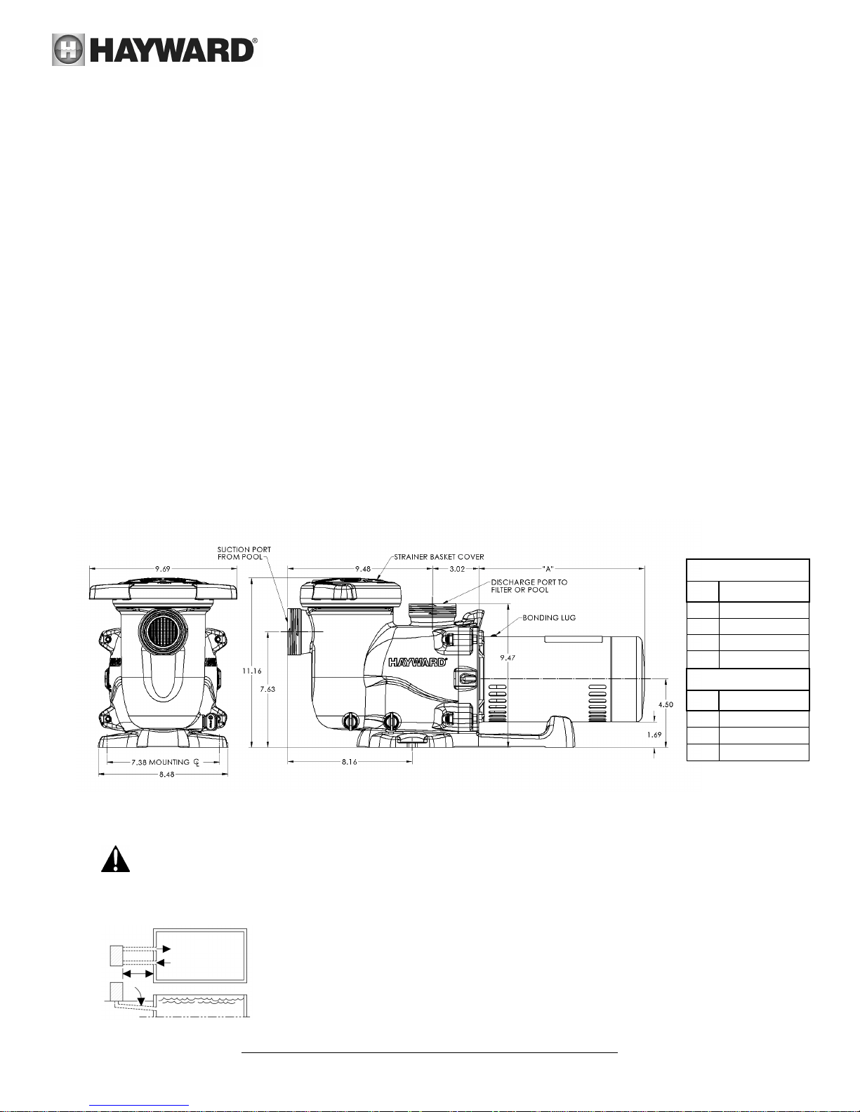
2.3. Product Dimensions
3. Installation and Wiring
WARNING – This product should be installed and serviced only by a qualified professional.
3.1. Pump Location
Single Speed
HP Dim "A"
0.75
1 11.3"
1.5 12.4"
2 12.5"
10.8"
Dual Speed
HP Dim "A"
1 12.0"
1.5 12.5"
2 13.0"
Locate pump as close to pool as practical and run suction lines as direct as possible to
reduce friction loss. Pump height location should be as close to pool water level as
possible and NOT to exceed 8 feet. Suction lines should have continuous slope upward
from lowest point in line. Joints must be tight (but not over-tightened). Suction line
diameter must equal or be larger than the discharge line diameter.
USE ONLY HAYWARD GENUINE REPLACEMENT PARTS
Page 6 of 20 Max-Flo XL Pump IS2300 Rev-A1
 Loading...