

Hayward SP1580, SP1540C, SP1580X15, SW1585X25, EP1550LX Owner's Manual
...
ISPFSERIES Rev G
PowerFlo LX
Pump Series
Owner’s Manual
™
/ PowerFlo II
Contents
Product Warnings……….………2
Installation……….……………..…4
Start-Up & Operation…….…….6
Shaft Seal Replacement……….7
Troubleshooting…………………..8
Replacement Parts………..….…10
Warranty …………………………..…11
Registration………………………….12
™
/ EP
INSTALLATION, OPERATION, & PARTS
IMPORTANT SAFETY INSTRUCTIONS
Basic safety precautions should always be followed, including the following: Failure to follow instructions can
cause severe injury and/or death.
This is the safety-alert symbol. When you see this symbol on your equipment or in this manual, look for
one of the following signal words and be alert to the potential for personal injury.
WARNING warns about hazards that could cause serious personal injury, death or major property
damage and if ignored presents a potential hazard.
CAUTION warns about hazards that will or can cause minor or moderate personal injury and/or property
damage and if ignored presents a potential hazard. It can also make consumers aware of actions that are
unpredictable and unsafe.
The NOTICE label indicates special instructions that are important but not related to hazards.
Hayward Pool Products
620 Division Street, Elizabeth, NJ 07207
Phone: (908) 355-7995
www.haywardnet.com
USE ONLY HAYWARD GENUINE REPLACEMENT PARTS 1
R
R
s
p
a
i
o
u
e
a
R
Wbeap
h
e
ngu
n
R
s
R
r
R
y
a
h
R
R
R
C
s
R
o
p
e
g
a
c
h
n
n
v
e
e
e
c
r
i
i
y
o
e
o
w
v
l
e
n
c
e
m
s
v
v
e
u
h
z
n
o
e
a
c
e
E
o
e
m
n
n
a
e
g
a
n
s
p
c
c
e
v
t
s
c
v
c
s
r
j
t
s
m
t
Y
r
w
m
n
d
n
a
m
o
e
e
m
o
m
a
m
e
e
t
h
s
a
o
c
o
r
u
d
a
c
p
a
N
t
.
m
b
t
y
r
:
m
w
s
n
m
a
e
d
f
t
t
e
t
t
c
c
t
m
m
t
v
A
g
y
y
n
u
i
i
s
o
i
s
s
e
m
e
e
h
o
m
m
r
p
e
A
o
t
r
s
a
i
t
i
E
i
s
s
c
u
c
t
e
e
u
u
t
o
s
e
d
u
n
u
f
u
i
r
e
a
,
c
s
e
v
r
f
e
m
o
e
t
e
t
m
o
s
r
WA
NING
-
Re
to follow
Suction in
severe inju
Hair Entra
Limb Entr
cracked, m
Body Suct
Eviscerati
sump or s
disembow
Mechanic
opening of
WA
WA
o
o D
o D
o T
o N
o R
o I
o I
instructions
NING
– Su
uction outlets
ry and/or deat
ment- Hair ca
pment- A limb
issing, or not s
on Entrapme
n/ Disembow
ction outlet co
lment.
l Entrapment-
a suction outl
NING
- To R
hen outlets ar
installed. Su
art, as measu
ual suction fitt
ual suction fitt
e maximum s
ever use Pool
place damag
addition two
idelines, follo
stallation of a
d and foll
can cause s
tion Entrap
and/or suctio
due to the fol
become enta
inserted into
ecurely attach
t- A negative p
elment - A ne
er which is, d
There is poten
t cover resulti
duce the ri
small enough
tion outlets in
ed from near
ngs shall be pl
ngs shall not b
stem flow rate
r Spa if any su
d, broken, cra
r more suction
all National,
acuum releas
w all inst
vere injury a
ent Hazard.
outlet covers
lowing entrap
gled in suctio
n opening of a
d can result in
ressure applie
ative pressure
maged, broke
tial for jewelry,
g in mechanic
k of Entrap
to be blocked
the same plan
oint to near po
aced in such l
e located on s
shall not exce
tion outlet co
ked, missing,
outlets per pu
State, and Loc
or vent syste
uctions
in
nd/or death
hich are, da
ent hazards:
outlet cover.
suction outlet
a mechanical
to a large por
applied directl
, cracked, mis
swimsuit, hai
l entrapment.
ent Hazards
by a person, a
e (i.e. floor or
int.
cations and di
ating areas or
d the flow rati
ponent is da
r not securely
p installed in
l codes applic
, which reliev
his owner’s
aged, broken,
sump or suctio
ind or swellin
tion of the bod
to the intesti
sing, or unsec
decorations, f
:
minimum of tw
all), must be i
stances to avo
on the backre
g as listed on
aged, broken,
attached sucti
accordance w
able.
s entrapping
manual and
cracked, missi
n outlet cover
of the limb.
y or limbs can
es through an
red can result
nger, toe or kn
o functioning
nstalled a mini
d “dual block
t for such seat
the suction ou
cracked, miss
n outlet comp
th latest ASM
uction, is reco
n the equip
ng, or unsecur
hat is damage
esult in an ent
unprotected s
in evisceratio
uckle to be ca
uction outlets
mum of three
ge” by a user.
ng areas.
let cover.
ng, or not sec
onents immed
, APSP Standa
mmended.
ment. Failur
d can cause
, broken,
rapment.
ction outlet
/
ght in an
per pump mus
eet (3’) [1 met
rely attached.
ately.
ds and CPSC
r]
WA
NING
– Fai
from the
and othe
frequentl
securely
prevent t
all times.
as a mean
start up, n
follow safe
and clamp
pool and s
be in open
back to th
open filter
is dischar
WA
WA
CAU
WA
WA
WA
WA
uction outl
NING
– Fai
material ca
NING
– Su
and replac
ttached.
TION
– Co
eir being u
NING
NING
NING
of access to t
NING
ty and operati
due to pressur
position. Befo
pool. Do not
manual air reli
ed.
– Ne
– Ne
–
omponents s
To r
– Ha
rmal operatio
a water circul
ts can resul
lure to keep
result in an
tion outlet
d at least e
ponents su
ed as mean
er operate o
er change th
duce risk of in
ch as the filtra
e pool.
ardous Pres
, and after pu
n instructions
in the system
tion system, a
re starting sys
hange filter co
f valve. Do no
ure to remo
e pressure t
in an increa
uction outl
increase po
omponents
ery ten year
h as the filtr
of access t
test the cir
e filter contr
ury, do not pe
ion system, p
ure.
Pool an
p shut off. St
could result in
, which could
ll system and
em pump, all s
ntrol valve pos
t close filter m
st plugs an
se potential
t componen
ential for su
ave a finite
or if found
tion system
the pool by
ulation syst
l valve posi
mit children to
mps, and hea
spa water cir
nd clear of cir
violent separa
ause property
ump controls
ystem valves
ition while sys
nual air relief
/or plugs u
for suction e
s clear of d
ction entrap
life, the cov
o be damag
, pumps and
young childr
m at more t
tion while th
use or climb o
ers must be p
ulation syste
ulation syste
ion of the pum
damage, seve
ust be in off
ust be set in a
em pump is ru
alve until a st
ed in winter
ntrapment a
bris, such a
ment as des
r/grate sho
d, broken,
heater mus
en.
an 30 PSI.
e pump is ru
n this product.
sitioned to pr
s operate und
equipment d
p housing and
e personal inj
osition and fil
position to all
nning. Before
ady stream of
zation of th
described
leaves, dirt
ribed above
ld be inspe
racked, mis
be position
nning.
Closely super
vent children f
r hazardous p
ring pump sta
cover, and/or
ry, or death. B
er manual air r
w system wat
tarting syste
water (not air
pool/spa
bove.
hair, paper
.
ted
ing, or not
d so as to
ise children a
rom using the
essure during
rt up. Failure t
ilter housing
efore servicing
elief valve mu
r to return
pump, fully
r air and wate
t
)
US
ONLY HA
WARD GE
UINE REPL
CEMENT P
RTS
2
WARNING – Separation Hazard. Failure to follow safety and operation instructions could result in violent separation
of pump and/or filter components. Strainer cover must be properly secured to pump housing with strainer cover lock ring. Before
servicing pool and spa circulation system, filters manual air relief valve must be in open position. Do not operate pool and spa
circulation system if a system component is not assembled properly, damaged, or missing. Do not operate pool and spa
circulation system unless filter manual air relief valve body is in locked position in filter upper body.
WARNING – Risk of Electric Shock. All electrical wiring MUST be in conformance with applicable local codes,
regulations, and the National Electric Code (NEC). Hazardous voltage can shock, burn, and cause death or serious property
damage. To reduce the risk of electric shock, do NOT use an extension cord to connect unit to electric supply. Provide a properly
located electrical receptacle. Before working on any electrical equipment, turn off power supply to the equipment.
WARNING – To reduce the risk of electric shock replace damaged wiring immediately. Locate conduit to prevent abuse
from lawn mowers, hedge trimmers and other equipment.
WARNING – Electrical ground all electrical equipment before connecting to electrical power supply. Failure to ground all
electrical equipment can cause serious or fatal electrical shock hazard.
WARNING – Do NOT ground to a gas supply line.
WARNING – To avoid dangerous or fatal electrical shock, TURN OFF POWER to all electrical equipment before working on
electrical connections.
WARNING – Failure to bond all electrical equipment to pool structure will increase risk for electrocution and could result
in injury or death. To reduce the risk of electric shock, see installation instructions and consult a professional electrician on how
to bond all electrical equipment. Also, contact a licensed electrician for information on local electrical codes for bonding
requirements.
Notes to electrician: Use a solid copper conductor, size 8 or larger. Run a continuous wire from external bonding lug to
reinforcing rod or mesh. Connect a No. 8 AWG (8.4 mm
pressure wire connector provided on the electrical equipment and to all metal parts of swimming pool, spa, or hot tub, and metal
piping (except gas piping), and conduit within 5 ft. (1.5 m) of inside walls of swimming pool, spa, or hot tub.
IMPORTANT - Reference NEC codes for all wiring standards including, but not limited to, grounding, bonding and other general
wiring procedures.
2
) [No. 6 AWG (13.3 mm2) for Canada] solid copper bonding wire to the
WARNING – Risk of Electric Shock. Connect only to a branch circuit protected by a ground-fault circuit-interrupter (GFCI).
Contact a qualified electrician if you cannot verify that the circuit is protected by a GFCI.
WARNING – Risk of Electric Shock . The electrical equipment must be connected only to a supply circuit that is protected
by a ground-fault circuit-interrupter (GFCI). Such a GFCI should be provided by the installer and should be tested on a routine
basis. To test the GFCI, push the test button. The GFCI should interrupt power. Push reset button. Power should be restored. If
the GFCI fails to operate in this manner, the GFCI is defective. If the GFCI interrupts power to the electrical equipment without the
test button being pushed, a ground current is flowing, indicating the possibility of an electrical shock. Do not use this electrical
equipment. Disconnect the electrical equipment and have the problem corrected by a qualified service representative before
using.
CAUTION – This pump is intended for use with permanently-installed pools and may be used with hot tubs and spas if so
marked. Do not use with storable pools. A permanently-installed pool is constructed in or on the ground or in a building such
that it cannot be readily disassembled for storage. A storable pool is constructed so that it is capable of being readily
disassembled for storage and reassembled to its original integrity.
SAVE THESE INSTRUCTIONS
USE ONLY HAYWARD GENUINE REPLACEMENT PARTS 3
Installation Instructions
Pump Location
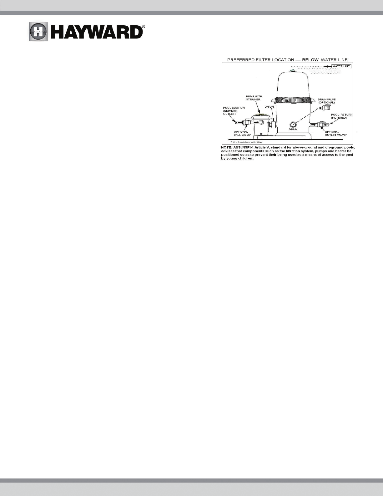
The PowerFlo LX™ and EP series pumps MUST be installed
below the pool water line (see Figure to right).
Self-priming PowerFlo II™ pumps may be installed up to four
(4) feet above the pool water line.
Install pump on a firm, level base or pad to meet all local and
national codes. The field supplied base or pad must be level
and vibration-free.
Pump motors require free circulation of air for cooling.
Do NOT install pump in a damp or non-ventilated location.
Though the pump is designed for outdoor use, it is strongly
advised to protect the electrical components from the
weather. Select a well-drained area, one that will not flood
when it rains.
Pump Mounting
Fasten pump to base or pad with screws or bolts to further reduce vibration and stress on pipe or hose joints. The
base MUST be solid - level - rigid - vibration free.
Pump mount must:
Allow pump inlet height to be as close to water level as possible.
Allow use of short, direct suction pipe (to reduce friction losses).
Allow for ball valves in suction and outlet piping.
Be protected from excess moisture and flooding.
Allow adequate access for servicing pump and piping.
Plumbing
Use TFE tape to seal threaded connections on molded plastic components. All plastic fittings must be new or
thoroughly cleaned before use. NOTE: Do NOT use Plumber’s Pipe Dope as it may cause cracking of the plastic
components.
When applying TFE tape to plastic threads, wrap the entire threaded portion of the male fitting with one to two layers
of tape. Wind the tape clockwise as you face the open end of the fitting, beginning at the end of the fitting.
The pump suction and outlet ports have molded-in thread stops. Do NOT attempt to force hose connector fitting
past this stop. It is only necessary to tighten fittings enough to prevent leakage. Tighten fitting by hand and then
use a tool to engage fitting an additional 1 ½ turns. Use care when using TFE tape as friction is reduced
considerably; do NOT over-tighten fitting or you may cause damage. If leaks occur, remove connector, clean off old
Teflon tape, re-wrap with one to two additional layers of TFE tape, and re-install connector.
Piping - Flexible Hose, PVC, or Reinforced Hose are all acceptable piping methods
For pump outlet use 1-1/2" PVC pipe or reinforced hose. For pump suction on ALL models, use 1-1/2" reinforced
hose. Increase size if a long run is needed. For pipe larger than port, use reducing fitting in strainer port.
To avoid pump strain, support suction and outlet independently. Place supports near pump. To avoid strain left by a
gap at last connection, start all piping at pump and run pipe AWAY from pump.
NEVER use suction pipe SMALLER than pump suction connections. Suction pipe inlet must be lower than pump
inlet port.
USE ONLY HAYWARD GENUINE REPLACEMENT PARTS 4
 Loading...