How it Works
Log In / Sign Up
Buy Points
How it Works
FAQ
Contact Us
Questions and Suggestions
Users
HAYWARD
Loading...
S
S210SLE
S210SLETL
S210SV
S210T
2
S210T2
S210TLE
S220T2
S240SLBTL
S240SLE
S240SLETL
S240TLE
S244SV
2
S244T2
S270T
2
S270T2
S2P213
S2P263
S2P263E
S2P316
S2P453
S301T
S310S
S310SLBTL
S310SLE
S310SLETL
S310T
S310T2
2
S311SX
3
S311SXV
3
S360SLBTL
S360SLE
S360SLETL
S360SX
3
S360T2
2
Saline C®
Saline C HCSC60EU
Salt & Swim
3
Salt & Swim®
3
Salt & Swim™ 3C
3
Salt & Swim 3C Pro
Salt & Swim 3C SAS
Salt Swim 3C SAS-CUL
Salt & Swim CELL
Salt&Swim SAS-AU
SandMaster SM1700T
SandMaster SM1900T
SAS-CELL
SCUBA
2
SCUBA DAVE
SDMAN
2
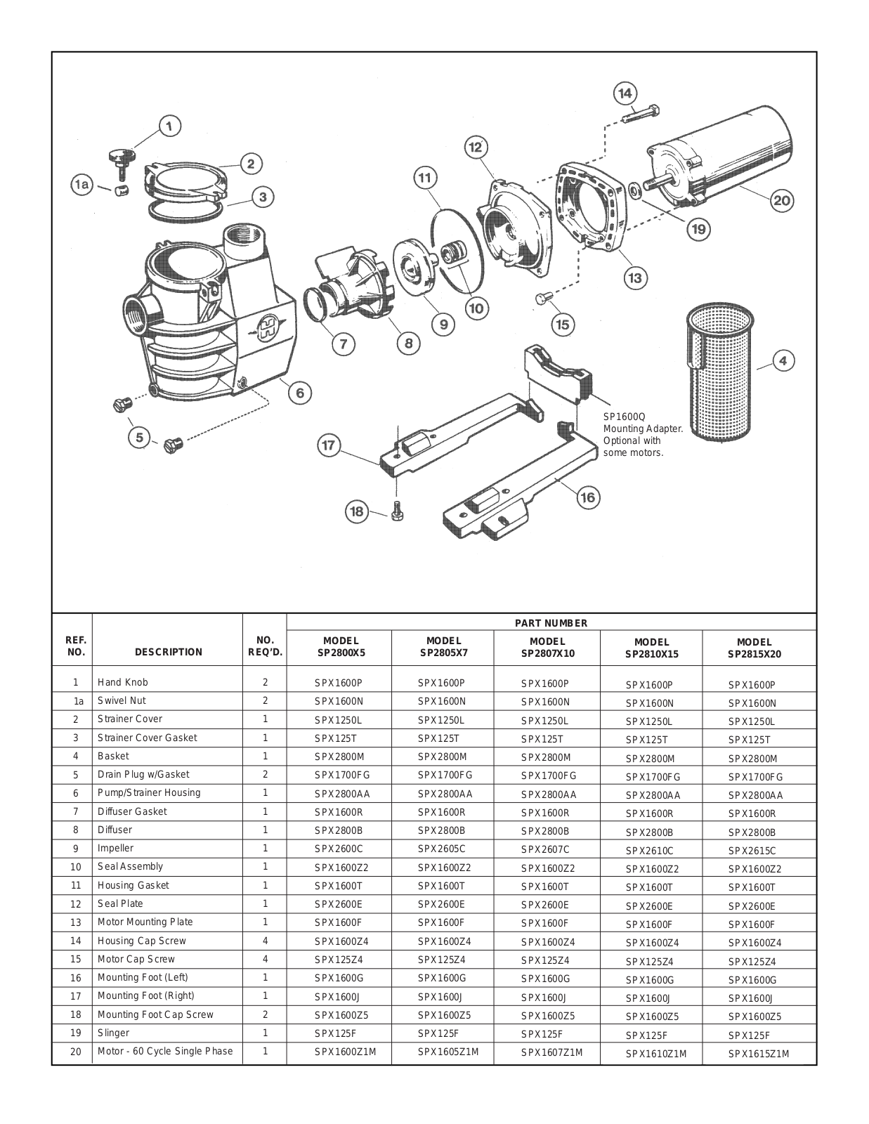
SELF-PRIMING MAX-FLO PUMP
SELF-PRIMING SUPER PUMP
Sense and Dispense
2
SharkVac
4
SharkVAC by ®
SharkVAC XK
SharkVAC XL
4
SharkVAC XL™
SharkVAC XL Pilot
4
Side Mount
SP0522
SP0522S
SP0523
SP0523S
SP0524
SP0530
SP0530S
SP0531
SP0531S
SP0570N
2
SP0571N
SP0572NL
SP0573NL
2
SP0580
SP0580S
SP0581
SP0581S
SP0582L
SP0582LS
SP0583L
SP0583LS
SP0590HSL
SP0590SL
SP0591HSL
SP0591SL
SP0592HSL
SP0600U
SP0604C
SP0606C
SP0609C
SP0610C
SP0710XR50
SP0715XR50
SP0740DE
2
SP1030
SP1048AV
SP1049AV
SP-1575LXTL
SP-1580TL
SP-1580X15TL
Loading...
Loading...
Nothing found
SELF-PRIMING MAX-FLO PUMP
installation Guide
4 pgs
346.3 Kb
0
Table of contents
Loading...
HAYWARD SELF-PRIMING MAX-FLO PUMP installation Guide
...
HAYWARD installation Guide
Download
Specifications and Main Features
Frequently Asked Questions
User Manual
Download
Page 1
Page 2
Page 3
Page 4
Loading...
+
hidden pages
Unhide
You need points to download manuals.
1 point = 1 manual.
You can buy points or you can get point for every manual you upload.
Buy points
Upload your manuals