

Hayward S-210T, S-220T, S-210TR, S-244T Quick Manual
®
Your Hayward Pro Series high rate sand lter is a high performance totally corrosion-proof lter that blends superior ow
characteristics and features with ease of operation. It represents the very latest in high rate sand lter technology. It is
virtually foolproof in design and operation and when
installed, operated and maintained according to instructions, your lter with produce clear, sparkling water with
only the least attention and care.
HOW IT WORKS
Your lter uses a special lter sand to remove dirt particles
from pool water. Filter sand is loaded into the lter tank and
functions as the permanent dirt removing media. The pool
water which contains suspended dirt particles is pumped
through your piping system and is automatically directed by
the patented lter control valve to the top of the lter tank.
As the pool water is pumped though the lter sand, dirt
particles are trapped by the sand bed, and ltered out. The
cleaned pool water is returned from the bottom of the lter
tank, through the control valve and back to the pool through
the piping system. This entire sequence is continuous and
automatic and provides for total recirculation of pool water
through your lter and piping system.
After a period of time the accumulated dirt in the lter
causes a resistance to ow, and the ow diminishes. This
means it is time to clean (backwash) your lter. With the
control valve in the Backwash position, the water ow is
automatically reversed though the lter so that it is directed
to the bottom of the tank, up through the sand, ushing the
previously trapped dirt and debris out of the waste line.
Once the lter is backwashed (cleaned) of dirt, the control
valve is manually re-sequenced to Rinse, and then Filter, to
resume normal ltering.
INSTALLATION
If you own an above ground pool please see note: NSP1-4
Article V, for safe proper installation of the equipment
package.
Only simple tools (screwdriver and wrenches), plus pipe
sealant for plastic adapters, are required to install and/or
service the lter.
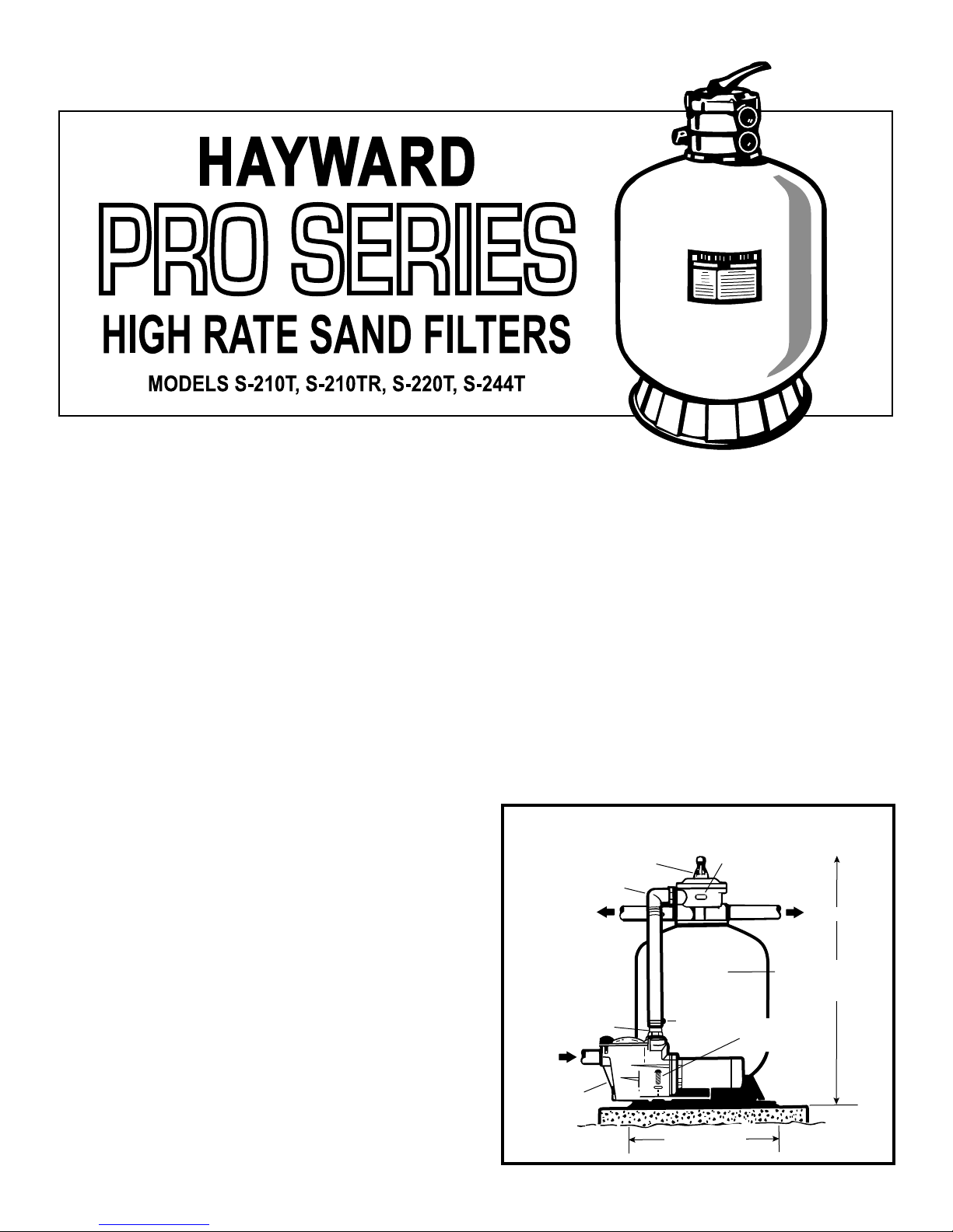
The lter should be placed on a level concrete slab, very
rm ground, or equivalent, as recommended by your
pool dealer. Position the lter so that the piping connections, control valve and winter drain are convenient and
accessible for operation, servicing and winterizing.
Assemble pump and pump mounting base, (if supplied)
to the lter according to instructions packed with the
base.
1.
2.
STRAIGHT ADAPTER
RETURN TO POOL
FROM
POOL
PUMP
ELBOW ADAPTER
VARI-FLO
CONTROL VALVE
SIGHT GLASS
FILTER
CLAMP
PUMP
MOUNTING
SCREW/WASHER
TYPICAL INSTALLATION
24 - 1/2” (63 cm)
WASTE LINE
38” (96 cm) S-210T
38” (96 cm) S-210TR
41” (104 cm) S-220T
42” (106 cm) S-244T
IS 210T HC 13
www.haywardpool.ca
SPECIFICATIONS
MODEL NO.
a S-210T
b S-210TR
c S-220T
d S-244T
EFFECTIVE
FILTRATION AREA
FT2
2.20
2.20
2.64
3.14
M2
0.20
0.20
0.25
0.29
DESIGN FLOW RATE
GPM
44
44
53
63
MAXIMUM WORKING
LPM
166
166
200
238
PSI
50
50
50
50
Note: NSPI-4 Article V, standard for above ground
and on ground pools, advises that components
such as the ltration system, pumps and heater be
positioned so as to prevent their being used as a
means of access to the pool by young children.
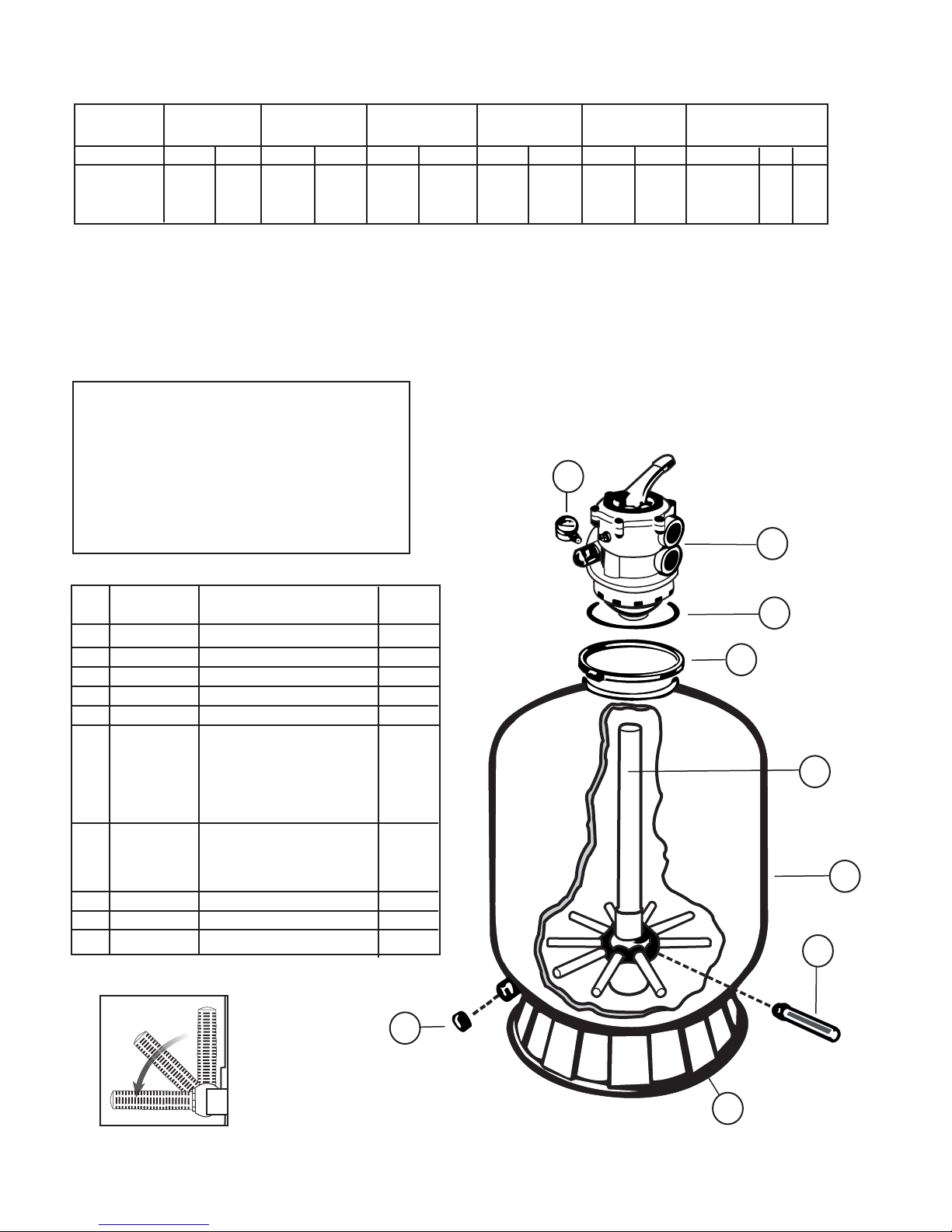
PARTS
Model S-210T, S-210TR, S-220T, S-244T
PRESSURE
BAR
3.45
3.45
3.45
3.45
SIDE CLEARANCE
INCH
18
18
18
18
CM
45
45
45
45
ABOVE CLEARANCE
INCH
18
18
18
18
2
CM
45
45
45
45
MEDIA REQUIRED
TYPE
.45 mm - .55 mm
No 20 or No 1/2
Silica Filter Sand
LBS
225
225
250
300
1
KG
100
100
114
136
REF.
NO.
1
1
2
3
4
5a
5b
5c
5d
5e
6a
6b
6c
6d
7
8
9
PART NO.
SP-0714-TC
SP071620T
EC-2708-61
GM-600-F
GM-600-NM
S-210-DA
S-210-DA
S-220-DA
S-244-DA
S-270-DA2X
S-210-AA-1
S-210-AAB
S-220-AA-1
S-244-AA-1
S-240-D
S-180-LM
S-200-J
DESCRIPTION
1½” Vari-o Control Valve Ass’y
2” Vari-Flo Control Valve
Pressure Gauge
Valve / Tank O-Ring
Flange Clamp (Valve Tank)
Lateral Assembly with Center
Pipe - 1½”
}
Lateral Assembly with Center
Pipe - 2”
Filter Tank with Skirt,
Complete Lateral Assembly
Lateral
Drain Cap & Gasket
Filter Support Stand (Skirt)
NO.
REQ’D.
1
opt.
1
1
1
1
1
10
1
1
8
3
4
a
b
5
c
d
e
a
b
6
c
d
7
Figure A
9
www.haywardpool.ca
 Loading...