

HAYWARD S170TSCPE User Manual
OWNER’S MANUAL
INSTALLATION, OPERATION & PARTS
MODELS:
HIGH-RATE SAND
IS170TSC
Rev. B
S170TSCPE
S190TSCPE
S190TSCPFT
S190TSCPT
FILTER
Basic safety precautions should always be followed, including the following: Failure to follow instructions can cause severe
injury and/or death.
This is the safety-alert symbol. When you see this symbol on your equipment or in this manual, look for one of the
following signal words and be alert to the potential for personal injury.
WARNING warns about hazards that could cause serious personal injury, death or major property damage and if
ignored presents a potential hazard.
CAUTION warns about hazards that will or can cause minor or moderate personal injury and/or property damage
and if ignored presents a potential hazard. It can also make consumers aware of actions that are unpredictable and unsafe.
The NOTICE label indicates special instructions that are important but not related to hazards.
Use only High Rate Sand No. 20 Silica Sand (.45mm - .55mm)
SAVE THIS INSTRUCTION MANUAL
HAYWARD POOL PRODUCTS, INC.
620 Division Street Elizabeth, NJ 07207 Tel: 908-351-5400
WWW.HAYWARDPOOL.COM
Page 2 of 8 IS170TSC Rev B
- WARNING - Read and follow all instructions in this owner’s manual and on the equipment. Failure to
follow instructions can cause severe injury and/or death.
WARNING – Suction Entrapment Hazard.
Suction in suction outlets and/or suction outlet covers which are, damaged, broken, cracked, missing, or unsecured can cause severe injury
and/or death due to the following entrapment hazards:
Hair Entrapment- Hair can become entangled in suction outlet cover.
Limb Entrapment- A limb inserted into an opening of a suction outlet sump or suction outlet cover that is damaged, broken, cracked,
missing, or not securely attached can result in a mechanical bind or swelling of the limb.
Body Suction Entrapment- A negative pressure applied to a large portion of the body or limbs can result in an entrapment.
Evisceration/ Disembowelment - A negative pressure applied directly to the intestines through an unprotected suction outlet sump or
suction outlet cover which is, damaged, broken, cracked, missing, or unsecured can result in evisceration/ disembowelment.
Mechanical Entrapment- There is potential for jewelry, swimsuit, hair decorations, finger, toe or knuckle to be caught in an opening of a
suction outlet cover resulting in mechanical entrapment.
WARNING - To Reduce the risk of Entrapment Hazards:
o When outlets are small enough to be blocked by a person, a minimum of two functioning suction outlets per pump must be
installed. Suction outlets in the same plane (i.e. floor or wall), must be installed a minimum of three feet (3’) [1 meter] apart, as
measured from near point to near point.
o Dual suction fittings shall be placed in such locations and distances to avoid “dual blockage” by a user.
o Dual suction fittings shall not be located on seating areas or on the backrest for such seating areas.
o The maximum system flow rate shall not exceed the flow rating of as listed on Table 2.
o Never use Pool or Spa if any suction outlet component is damaged, broken, cracked, missing, or not securely attached.
o Replace damaged, broken, cracked, missing, or not securely attached suction outlet components immediately.
o In addition two or more suction outlets per pump installed in accordance with latest NSPI, IAF Standards and CPSC guidelines, follow all
National, State, and Local codes applicable.
o Installation of a vacuum release or vent system, which relieves entrapping suction, is recommended.
WARNING – Failure to remove pressure test plugs and/or plugs used in winterization of the pool/spa from the suction
outlets can result in an increase potential for suction entrapment as described above.
WARNING – Failure to keep suction outlet components clear of debris, such as leaves, dirt, hair, paper and other
material can result in an increase potential for suction entrapment as described above.
WARNING – Suction outlet components have a finite life, the cover/grate should be inspected frequently and replaced
at least every ten years or if found to be damaged, broken, cracked, missing, or not securely attached.
CAUTION – Components such as the filtration system, pumps and heater must be positioned so as to prevent their
being used as means of access to the pool by young children.
WARNING – Never operate or test the circulation system at more than 40 PSI.
CAUTION – All electrical wiring MUST be performed by a qualified professional, and MUST conform to local codes
and regulations.
WARNING – Never change the filter control valve position while the pump is running.
spa water circulation system, all system and pump controls must be in off position and filter manual air relief valve must be in open position. Before
starting system pump, all system valves must be set in a position to allow system water to return back to the pool. Do not change filter control valve
position while system pump is running. Before starting system pump, fully open filter manual air relief valve. Do not close filter manual air relief
valve until a steady stream of water (not air or air and water) is discharged.
WWW.HAYWARDPOOL.COM USE ONLY HAYWARD GENUINE REPLACEMENT PARTS
WARNING – Hazardous Pressure. Pool and spa water circulation systems operate under hazardous pressure during
start up, normal operation, and after pump shut off. Stand clear of circulation system equipment during pump start up. Failure to
follow safety and operation instructions could result in violent separation of the pump housing and cover, and/or filter housing and
clamp due to pressure in the system, which could cause property damage, severe personal injury, or death. Before servicing pool and
WARNING – Separation Hazard. Failure to follow safety and operation instructions could result in violent separation of
pump and/or filter components. Strainer cover must be properly secured to pump housing with strainer cover lock ring. Before servicing
pool and spa circulation system, filters manual air relief valve must be in open position. Do not operate pool and spa circulation system
if a system component is not assembled properly, damaged, or missing. Do not operate pool and spa circulation system unless filter
manual air relief valve body is in locked position in filter upper body.
WARNING – Electrical Ground motor before connecting to electrical power supply. Failure to ground pump motor can
cause serious or fatal electrical shock hazard.
WARNING – Do NOT ground to a gas supply line.
Page 3 of 8 IS170TSC Rev B
WARNING – To avoid dangerous or fatal electrical shock, turn OFF power to motor before working on electrical connections.
WARNING – Failure to bond pump to pool structure will increase risk for electrocution and could result in injury or death. To reduce the
risk of electric shock, see installation instructions and consult a professional electrician on how to bond pump. Also, contact a licensed electrician for
information on local electrical codes for bonding requirements.
Your Hayward Pro Series high-rate sand filter is a high
performance, totally corrosion-proof filter that blends superior
flow characteristics and features with ease of operation. It
represents the very latest in high-rate sand filter technology. It
is virtually foolproof in design and operation and when
installed, operated and maintained according to instructions,
your filter will produce clear, sparkling water with only mini mal
attention and care.
HOW IT WORKS
Your filter uses special filter sand to remove dirt particles from
pool water. Filter sand is loaded into the filter tank and
functions as the permanent dirt removing media. The pool
water, which contains suspended dirt particles, is pumped
through your piping system and is automatically directed by the
patented filter control valve to the top of the filter tank. As the
pool water is pumped through the filter sand, dirt particles are
trapped by the sand bed, and filtered out. The cleaned pool
water is returned from the bottom of the filter tank, through the
control valve and back to the pool through the piping system.
This entire sequence is continuous and automatic and provides
total recirculation of pool water through your filter and piping
system.
After a period of time, the accumulated dirt in the filter causes
a resistance to flow, and the flow diminishes. This means it is
time to clean (backwash) your filter. With the control valve in
the backwash position, the water flow is automatically reversed
through the filter so that it is directed to the bottom of the tank,
up through the sand, flushing the previously trapped dirt and
debris out the waste line. Once the filter is backwashed
(cleaned) of dirt, the control valve is manually resequenced to
Rinse, and then Filter, to resume normal filtering.
INSTALLATION
Only simple tools (screwdriver and wrenches), plus pipe
sealant for plastic adapters, are required to install and/or
service the filter.
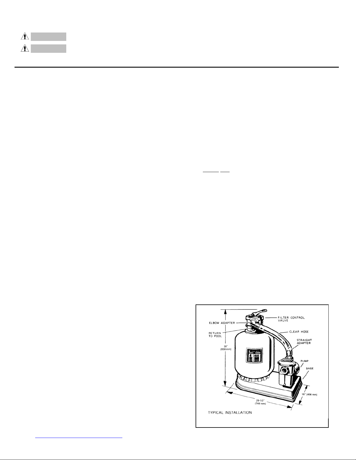
1. The filter system should be installed, not more than 6 feet
above pool water level, on a level concrete slab, very firm
ground, or equivalent, as recommended by your pool
dealer. Position the filter so that the piping connections,
control valve and winter drain are convenient and
accessible for operation, service and winterizing.
2. Assemble pump and pump mounting base, No.
S160TPAK1, or S160TPAK3 (if supplied) to the filter
according to instructions packed with the base.
3. Loading sand media. Filter sand media is loaded through
the top opening of the filter.
a. Loosen flange clamp and remove Filter Control Valve (if
previously installed).
b. Cap internal pipe with sand shield to prevent sand from
entering it. Be sure pipe is securely in place in bottom
underdrain hub.
c. We recommend filling tank appro ximately 1/2 way with
water to provide a cushioning effect when the filter sand
is poured in. This helps protect the underdrain laterals
from excessive shock. (Be sure the winter drain cap is
securely in place on drain pipe).
WWW.HAYWARDPOOL.COM USE ONLY HAYWARD GENUINE REPLACEMENT PARTS
NOTE: Check to confirm all laterals are in the down
position before loading with sand. (See Figure A.)
d. Carefully pour in correct amount and grade of filter
sand, as specified on Table 1. (Be sure center pipe
remains centered in opening). Sand surface should be
leveled and should come to within 6" of the top of the
filter tank. Remove sand shield from internal pipe.
4. Assemble Filter Control Valve to filter tank.
a. Loosely pre-as semble both halves of the clamp with one
screw and one nut, turning the nut 2 or 3 t urns. Do not
tighten. Wipe filter flange clean.
b. Insert Filter Control Valve (with valve/flange 0-ring in
place) into the tank neck, taking care that the center pipe
slips into the hole in the bottom of the valve. Install clamp
tank and valve flange and assemble second screw
around
and nut. Tighten just enough so that the valve may be
rotated on tank for final positioning.
c. Wrap two turns of Teflon pipe sealant tape manufactured
for plastic pipe on the ¼” NPT male end of gauge.
Carefully screw pressure gauge, into 1/4"NPT tapped
hole in valve body. Do not o ve r tighten.
d. Connect pump to control valve opening marked PUMP
according to instructions. After connections are made,
tighten valve flange clamp with screwdriver, tapping
around clamp with screwdriver handle to help seat valve
flange clamp.
5. Make return to pool pipe connection to control valve
opening marked RETURN and complete other necessary
plumbing connections, suction lines to pump, waste, etc.
6. Make electrical connections to pump per pump instructions.
7. To prevent water leakage, be sure winter drain cap is
securely in place and all pipe connections are tight.
 Loading...