

Page 1
Your Hayward S166T high-rate sand filter is a high
performance, totally corrosion-proof filter that blends
superior flow characteristics and features with ease of
operation. It represents the very latest in high-rate sand
filter technology. It is virtually foolproof in design and
operation and when installed, operated and maintained
according to instructions, your filter will produce clear,
sparkling water with only the least attention and care.
HOW IT WORKS
Your filter uses special filter sand to remove dirt particles
from pool water. The sand is loaded into the filter tank
and functions as the permanent dirt removing media.
The pool water, which contains suspended dirt particles,
is pumped through your piping system and is
automatically directed by the patented filter control
valve to the top of the filter tank. As the pool water is
pumped through the filter sand, dirt particles are
trapped by the sand bed, and filtered out. The cleaned
pool water is returned from the bottom of the filter tank,
through the control valve and back to the pool through
the piping system. This entire sequence is continuous
and automatic and provides for total recirculation of pool
water through your filter and piping system.
After a period of time, the accumulated dirt in the filter
causes a resistance to flow, and the flow diminishes. This
means it is time to clean (backwash) your filter. With the
control valve in the backwash position, the water flow is
automatically reversed through the filter so that it is
directed to the bottom of the tank, up through the sand,
flushing the previously trapped dirt and debris out the
waste line. Once the filter is backwashed (cleaned) of
dirt, the control valve is manually resequenced to Rinse,
and then Filter, to resume normal filtering.
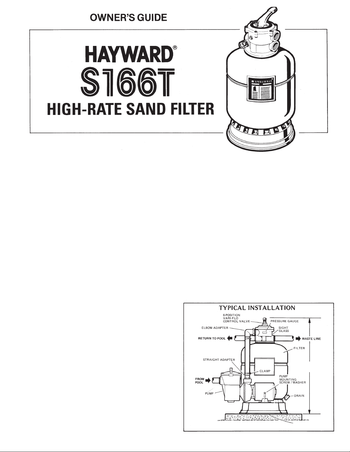
INSTALLATION
Only simple tools (screwdriver and wrenches), plus pipe
sealant for plastic adapters, are required to install and/or
service filter.
The filter should be placed on a level concrete slab,
very firm ground, or equivalent as recommended by
your pool dealer. Position the filter so that the piping
connections, control valve and winter drain are
convenient and accessible for operation, servicing
and winterizing.
Your filter is supplied complete with an optional
pump mounting base which is pre-drilled for use with
Hayward Power-Flo LX series pumps. The pump to
filter connecting hoses supplied will accommodate
Power-Flo LX pumps used with the mounting base,
and Max-Flo or Super Pump installed at surface
level. To connect pump to filter:
Screw straight adapter, using Teflon pipe sealant
tape or Permatex No. 2, securely into pump
discharge. (Do not overtighten.)
Screw elbow adapter, using Teflon pipe sealant
tape or Permatex No. 2, securely into opening in
control valve marked PUMP. (Do not overtighten.)
Elbow should point just over RETURN opening.
1.
2.
a.
b.
IS166TN2-00
PUMP MOUNTING
BASE (S164C)
33”
(84 cm)
Page 2
SPECIFICATIONS
MODEL
NUMBER
EFFECTIVE
FILTRATION AREA
DESIGN
FLOW RATE
MAXIMUM WORKING
PRESSURE
REQUIRED CLEARANCE MEDIA REQUIRED
FT
2
1.4
S166T
M
2
0.13
GPM
35
LPM
133
PSI
50
BAR
3.45
INCH
18
INCH
18
MM
457
MM
457
FILTER SAND*
0.45-0.55
LBS
100
KGS
45
ABOVE
SIDE TYPE AMOUNT
*Also known as No. 20 or No. 1/2 Silica Sand.
NOTE: ANSI/NSPI-4 Article V, standard for above-ground
and on-ground pools, advises that components such
as the filtration system, pumps and heater be
positioned so as to prevent their being used as a
means of access to the pool by young children.
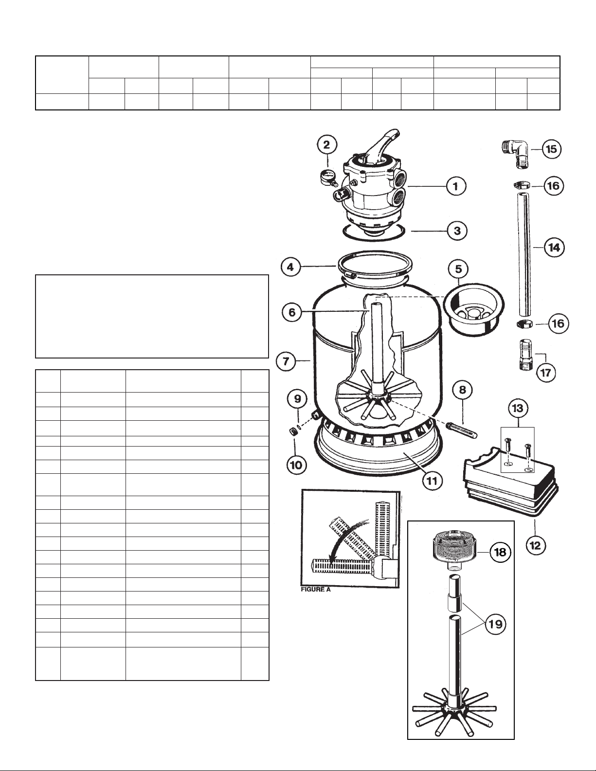
PARTS
Model S166T
S166T1575XS
S166T1575XSN2
REF.
NO.
1
2
3
4
5
6
8
9
10
11
12
13
14*
15*
16*
17*
18**
19**
NO.
REQ’D.
1
1
1
1
1
1
1
10
1
1
1
1
2
1
1
2
1
1
1
PART NO.
SP071113
ECX27081
GMX600F
GMX600NS
SX202S
SX164DA
SX200Q
SX180G
SX180H
SX164B
SX164C
ECX1108A
SX160Z5
SPX1105Z4
ECX18028
SPX1091Z2
N2SABG
SX164DAN2KIT
DESCRIPTION
Vari-Flo Control Valve Assembly
Pressure Gauge
Valve/Tank O-Ring
Flange Clamp (Valve-Tank)
Sand Shield
Lateral Assembly with Center Pipe
Filter Tank with Skirt,
Complete Lateral Assembly
Lateral
Gasket
Drain Cap
Filter Support Stand (Skirt)
Pump Base
5/16” x 3/4” Mounting Screw Kit
1-1/2” Hose
1-1/2” Elbow Adapter
Hose Clamp
1-1/2” Straight Hose Adapter
Nature2Canister
Folding Umbrella Lateral Assembly
w/Center Pipe for Nature
2
Canister
*Furnished with PAK or System only.
**Included only on filters supplied with SwimPure Canister
SX164AA17
SwimPure Option
Page 3

STOP here and load media per instructions (No. 3).
Place hose clamps on clear hose and fit hose over
straight and elbow adapters and secure with clamps. If
it is difficult to fit hose over the adapters, place hose in
hot water for several minutes.
NOTE: To prevent breakage and damage to pump and
control valve, use only pipe sealants specifically formulated
for plastics. Do not overtighten fittings or adapters.
Loading sand media. Filter sand media is loaded through
the top opening of the filter.
Loosen flange clamp and remove Filter Control Valve
(if previously installed).
Cap internal pipe with sand shield to prevent sand
from entering it. Be sure pipe is securely in place in
bottom underdrain hub.
We recommend filling tank approximately 1/2 way with
water to provide a cushioning effect when the filter
sand is poured in. This helps protect the underdrain
laterals from excessive shock. (Be sure the winter
drain cap is securely in place on drain pipe.) Note:
Check to confirm all laterals are in the down
position before loading with sand. (See Figure Aon
Page 2.)
Carefully pour in correct amount and grade of filter
sand, as specified. (Be sure center pipe remains
centered in opening). Sand surface should be leveled
and should come to about the middle of the filter tank.
Remove sand shield from center pipe.
NOTE: If your sand filter is equipped with the SwimPure
system or you are installing the SwimPure Retrofit Kit, then
please follow the steps in the Instruction Sheet included in
the SwimPure carton.
Assemble Filter Control Valve to filter tank.
Wipe filter flange clean.
To install clamp, loosely preassemble both halves of the
clamp with one screw and one nut, turning the nut two
or three times. Place clamp assembly on the filter neck.
Insert filter control valve (with valve/flange O-ring in
place) into the tank neck, taking care that the center
pipe slips into the hole in the bottom of the valve.
Install clamp around tank and valve flange and
assemble second screw and nut. Tighten both sides of
clamp alternately and evenly. Make sure you tighten
just enough so that the valve may be rotated on the
tank for final positioning.
Carefully screw the pressure gauge, with pipe tape,
into 1/4” tapped hole in valve body. Do not overtighten.
Connect pump to control valve opening marked
“PUMP” according to the instructions.
Tighten both sides of clamp alternately and evenly. Use
a correctly sized large screw driver and tighten firmly
to obtain a good seal.
Please be sure to place vinyl protector caps over ends of
screws.
Make return to pool pipe connection to control valve
opening marked RETURN and complete other necessary
plumbing connections, suction lines to pump, waste, etc.
Make electrical connections to pump per pump
instructions. Be sure all circuits are protected by a
properly-sized ground fault circuit interrupter (GFCI).
To prevent water leakage, be sure winter drain cap is
securely in place and all pipe connections are tight.
NOTE: If you have installed a SwimPure system, then
please refer to Step 2 in the SwimPure Instruction Sheet
(“Balance the Pool Water”).
INITIAL START-UP OF FILTER
Be sure correct amount of filter sand media is in tank and
that all connections have been made and are secure.
Depress Vari-Flo control valve handle and rotate to
BACKWASH position. (To prevent damage to control
valve seal, always depress handle before turning.)
Prime and start pump according to pump instructions
allowing the filter tank to fill with water. CAUTION: All
suction and discharge valves must be open when
starting the pump. Failure to do so could cause
severe personal injury and/or property damage.
Once water flow is steady out the waste line, run the
pump for at least 1 minute. The initial backwashing of
the filter is recommended to remove any impurities or fine
sand particles in the sand media.
Turn pump off, set valve to RINSE position. Start pump
and operate until water in sight glass is clear—about 1/2
to 1 minute. Turn pump off, set valve to FILTER position
and restart pump. Your filter is now operating in the
normal filter mode, filtering particles from the pool water.
Adjust pool suction and return valves to achieve desired
flow. Check system and filter for water leaks and tighten
connections, bolts, nuts, as required.
Note the initial pressure gauge reading when the filter is
clean. (It will vary from pool to pool depending upon the
pump and general piping system). As the filter removes
dirt and impurities from the pool water, the accumulation
in the filter will cause the pressure to rise and flow to
diminish. When the pressure gauge reading is 6-8 lbs.
(2.7-3.6 kgs.) higher than the initial “clean” pressure you
noted, it is time to backwash (clean) the filter (see
BACKWASH under Filter Control Valve Functions).
NOTE: During initial clean-up of the pool water, it
may be necessary to backwash frequently due to the
unusually heavy initial dirt load in the water.
CAUTION: To prevent unnecessary strain on piping
system and valving, always shut off pump before
switching Filter Control Valve positions.
To prevent damage to the pump and filter and for proper
operation of the system, clean pump strainer and skimmer
baskets regularly.
FILTER CONTROL VALVE FUNCTIONS
FILTER–Set valve to FILTER for normal filtering. Also use
for regular vacuuming.
BACKWASH–For cleaning filter. When filter pressure
gauge rises 6-8 lbs. (2.7-3.6 kgs.) above start-up (clean
pressure):
Stop the pump, set valve to BACKWASH. Start pump and
backwash, approximately 2 minutes or less, depending on
dirt accumulation, until water in sight glass is clear . Proceed
to RINSE.
3.
a.
b.
c.
d.
4.
a.
b.
c.
d.
e.
f.
g.
h.
5.
6.
1.
7.
2.
3.
c.
4.
5.
6.
Page 4

RINSE—After backwashing, with pump off, set valve to
RINSE. Start pump and operate for about 1/2 to 1 minute. This
ensures that all dirty water from backwashing is rinsed out of
the filter to waste, preventing possible return to the pool. Stop
pump, set valve to FILTER and start pump for normal filtering.
WATER—To bypass filter for draining or lowering water level
and for vacuuming heavy debris directly to waste.
RECIRCULATE—Water is recirculated through the pool
system, bypassing the filter.
CLOSED—Shuts off flow from pump to filter.
VACUUMING—Vacuuming can be performed directly into the
filter. When vacuuming heavy debris loads, set valve to WASTE
position to bypass the filter and vacuum directly out to waste.
WINTERIZING
Completely drain tank by unscrewing drain cap at base of
filter tank. Leave cap off during winter.
Depress Vari-Flo control valve handle and rotate so as to set
pointer on valve top between any two positions. This will
allow water to drain from the valve. Leave valve in this
“inactive” position.
Drain and winterize pump according to pump instructions.
SERVICE & REPAIRS
Consult your local authorized Hayward dealer or service center.
No returns may be made directly to the factory without the
expressed written authorization of Hayward Pool Products, Inc.
PROBLEM SOLVING LIST
LOW WATER FLOW SHORT FILTER CYCLES POOL WATER WON’T CLEAR UP
Check skimmer and pump
strainer baskets for debris.
Check for restrictions in
intake and discharge lines.
Check for air leak in intake
line (indicated by bubbles
returning to pool).
Backwash filter.
Check for algae in pool and
superchlorinate as required.
Be sure chlorine and pH
levels are in proper range
(adjust as required).
Check surface of filter sand
for crusting or caking
(remove 1” of sand if
necessary).
Check chlorine, pH and total
alkalinity levels and adjust
as required.
Be sure flow rate through
filter is sufficient.
Operate filter for longer periods.
Be sure Vari-Flo valve is set
on “Filter” position.
1.
2.
3.
4.
1.
2.
3.
1.
2.
3.
4.
REMEDY
POOL CHEMISTRY GUIDELINES
ACTION REQUIRED TO CORRECT POOL CHEMISTRY
TO RAISE TO LOWER
SUGGESTED POOL CHEMISTRY LEVELS
pH
TOTAL ALKALINITY
CHLORINE (UNSTABILIZED)
CHLORINE (STABILIZED)
CHLORINE STABILIZER
(Cyanuric Acid)
7.2 to 7.6
100 to 130 ppm
0.3 to 1.0 ppm
1.0 to 3.0 ppm
40 to 70 ppm
Add Soda Ash
Add Sodium Bicarbonate
Add Chlorine Chemical
Add Chlorine Chemical
Add Stabilizer
Add Muriatic Acid or Sodium Bisulphate
Add Muriatic Acid
No action - chlorine will naturally dissipate
No action - chlorine will naturally dissipate
Dilution - partially drain & refill pool with water
that has not been treated with Cyanuric Acid.
© 2000 Hayward Printed in U.S.A.
Rev. 11/00
PLEASE REALIZE . . .
Pure, clear swimming pool water is a combination of two
factors–adequate filtration and proper water chemistry balance.
One without the other will not give the clean water you desire.
Your filter system is designed for continuous operation.
However, this is not necessary for most swimming pools. You
can determine your filter operation schedule based on your pool
size and usage. Be sure to operate your filtration system long
enough each day to obtain at least one complete turnover of your
pool water.
To properly sanitize your pool, maintain a free chlorine level of
1 to 3 ppm and a pH range of 7.2 to 7.6. Insufficient chlorine or
an out of balance pH level will permit algae and bacteria to grow
in your pool and make it difficult for your filter to properly clean
the pool water.
1.
2.
3.
 Loading...