

Hayward ProGrid DE2420, ProGrid DE3620, ProGrid DE6020, ProGrid DE4820, ProGrid DE7220 Owner's Manual

ISDE2423 Rev D
ProGrid™ Vertical Grid D.E. Filter
Owner’s Manual
Contents
Product Warnings……………….…2
Introduction……….……..…..…..…4
Installation……….……………..……4
Starting Pump and Filter…………5
Filter Control Valve…………………6
Winterizing…………………………….9
Replacement Parts………..………10
Warranty..………………………..……11
Registration……………….………….12
IMPORTANT SAFETY INSTRUCTIONS
Basic safety precautions should always be followed, including the following: Failure to follow instructions
can cause severe injury and/or death.
This is the safety-alert symbol. When you see this symbol on your equipment or in this manual, look for
one of the following signal words and be alert to the potential for personal injury.
WARNING warns about hazards that could cause serious personal injury, death or major property
damage and if ignored presents a potential hazard.
CAUTION warns about hazards that will or can cause minor or moderate personal injury and/or property
damage and if ignored presents a potential hazard. It can also make consumers aware of actions that are
unpredictable and unsafe.
The NOTICE label indicates special instructions that are important but not related to hazards.
USE ONLY HAYWARD GENUINE REPLACEMENT PARTS 1
Hayward Pool Products
620 Division Street, Elizabeth, NJ 07207
Phone: (908) 355-7995
www.hayward.com
R
t
R
s
a
t
u
e
W
eap
h
e
ngu
n
R
u
R
a
R
a
T
d
o
p
e
g
/
t
e
s
o
a
c
h
a
b
e
w
v
e
e
e
c
r
i
i
y
o
e
o
w
v
u
S
p
s
n
o
e
a
c
e
o
P
w
h
m
n
O
o
n
m
n
a
e
e
a
t
e
n
p
c
c
e
s
e
m
r
r
g
s
m
t
m
n
v
u
e
,
X
e
A
r
w
m
o
a
r
n
y
a
o
e
e
m
o
m
a
m
o
o
o
e
e
o
.
e
d
a
c
p
a
f
e
a
b
c
m
a
m
A
N
t
m
.
t
b
o
c
m
w
s
n
m
a
e
p
a
e
t
t
o
m
r
s
t
c
t
m
m
t
v
n
d
n
e
n
d
l
a
o
g
u
i
s
o
o
i
s
w
s
s
,
n
m
r
p
e
o
p
i
o
g
d
e
R
r
n
a
k
s
a
i
i
E
o
.
n
e
e
u
u
t
o
s
l
a
D
o
D
m
c
C
e
e
n
n
a
f
u
i
r
p
u
t
t
o
e
r
f
e
m
o
e
k
p
n
h
s
a
m
i
t
e
i
o
s
r
i
s
m
y
WA
NING
-
Re
follow ins
Suction in
severe inju
Hair Entra
Limb Entr
cracked, m
Body Suc
Eviscerati
sump or s
disembow
Mechanic
opening of
suction o
material c
replaced
being use
on this pro
positioned
WA
WAR
o
o D
o D
o T
o N
o R
o I
o I
WA
WA
WA
CAU
ructions can
NING
– Suc
uction outlets
ry and/or deat
pment
- Hair c
pment
- A lim
issing, or not s
ion Entrapm
on/ Disembo
ction outlet co
lment.
l Entrapmen
a suction outl
NING
b
ual suction fitt
ual suction fitt
ever use Pool
- To R
hen outlets ar
installed. Su
art, as measu
e maximum s
place damag
addition two
idelines, follo
stallation of a
NING
–
tlets can resu
NING
–
n result in an
NING
t least every
to prevent chil
–
ION
–
as means of
uct. Closely
d and foll
ause severe i
tion Entrap
and/or suctio
due to the fol
n become ent
inserted into
ecurely attach
nt
- A negative
elment
er which is, d
- There is pot
t cover resulti
duce the ris
small enough
tion outlets in
ed from near
ngs shall be pl
ngs shall not b
stem flow rate
r Spa if any su
d, broken, cra
r more suction
all National,
acuum releas
Fail
re to remove
lt in an increa
Fail
ure to keep su
increase pot
Suc
tion outlet co
EVEN years o
Com
onents such
access to the
upervise child
dren from usin
w all inst
jury and/or d
ent Hazard.
outlet covers
lowing entrap
ngled in sucti
an opening of
d can result in
pressure appli
- A n
gative pressu
maged, broke
ntial for jewelr
g in mechanic
k of Entrapm
to be blocked
the same plan
oint to near po
aced in such l
e located on s
shall not exce
tion outlet co
ked, missing,
outlets per pu
State, and Loc
or vent syste
pressure test
e potential f
ction outlet c
ntial for sucti
ponents hav
if found to b
as the filtrati
pool by young
en at all times
them as a m
uctions
eath.
hich are, da
ent hazards:
n outlet cover
suction outle
a mechanical
d to a large p
e applied dire
, cracked, mis
, swimsuit, ha
l entrapment.
in
ent Hazards:
by a person, a
e (i.e. floor or
int.
cations and di
ating areas or
d the flow rati
ponent is da
r not securely
p installed in
l codes applic
, which reliev
plugs and/or
r suction entr
mponents cl
n entrapmen
a finite life,
damaged, br
n system, pu
children. To
Components
ans of access
his owner’s m
aged, broken,
sump or sucti
ind or swellin
rtion of the bo
tly to the intes
sing, or unsec
ir decorations,
minimum of tw
all), must be i
stances to avo
on the backre
g of as listed
aged, broken,
attached sucti
accordance w
able.
s entrapping
lugs used in
pment as de
ar of debris,
as described
he cover/grat
ken, cracked
ps and heate
educe risk of i
such as the filt
o the pool.
anual and on
cracked, missi
on outlet cove
of the limb.
dy or limbs ca
tines through
red can result
finger, toe or
o functioning
nstalled a mini
d “dual block
t for such seat
n Table 1.
cracked, miss
n outlet comp
th latest ASM
uction, is reco
interization
cribed above
uch as leaves
above.
e should be i
missing, or n
r must be pos
jury, do not p
ration system,
the equipmen
ng, or unsecur
that is damag
result in an e
n unprotected
in evisceratio
nuckle to be c
uction outlets
mum of three
ge” by a user.
ng areas.
ng, or not sec
onents immed
, APSP Standa
mmended.
f the pool/sp
, dirt, hair, pa
spected freq
ot securely at
itioned so as
rmit children t
pumps, and h
t. Failure to
d can cause
d, broken,
trapment.
suction outlet
/
ught in an
per pump mus
eet (3’) [1 met
rely attached.
ately.
ds and CPSC
a from the
er and other
ently and
ached.
o prevent the
use or climb
aters must be
r]
r
WAR
start up, n
NING
follow safe
and clamp
pool and s
be in open
back to th
open filter
is dischar
pump and
servicing p
circulation
system unl
system at
componen
blower wh
DEX2421J2
explosive
Never rely
bolt to 150
WAR
ty and operati
due to pressur
manual air reli
ed.
NING
ool and spa cir
ess filter manu
more than 50
inch-lbs. Befo
– Haz
rmal operatio
a water circul
position. Befo
pool. Do not
– Sep
or filter comp
system if a sys
s to explode,
n air purging t
nut/bolt asse
eparation.
n hand tighte
ardous Pres
, and after pu
n instructions
in the system
tion system, a
re starting sys
hange filter co
f valve. Do no
aration Haza
nents. Straine
culation syste
tem compone
al air relief val
SI. Do not p
ith risk of sev
e pump, filter
bly, and a DE
ing the clamp
e starting syst
USE
ure.
Pool an
p shut off. St
could result in
, which could
ll system and
em pump, all s
ntrol valve pos
t close filter m
rd.
Failure to
r cover must b
, filters manu
t is not assem
e body is in lo
rge the syste
re injury or de
or piping. Use
2422Z2 metal
nut to the cla
m pump, insu
NLY HAYW
spa water circ
nd clear of cir
violent separa
ause property
ump controls
ystem valves
ition while sys
nual air relief
ollow safety a
properly secu
l air relief valv
led properly,
ked position i
with compr
th to anyone
ONLY Haywar
reinforced sea
p bolt. Using
re filter manua
RD GENUI
ulation system
ulation syste
ion of the pum
damage, seve
ust be in off
ust be set in a
em pump is ru
alve until a st
d operation in
red to pump h
e must be in o
amaged, or m
filter upper b
ssed air. Pur
earby. Use on
clamp system
. Non-Haywar
¾” socket on
l air relief valv
E REPLAC
s operate und
equipment d
p housing and
e personal inj
osition and fil
position to all
nning. Before
ady stream of
structions cou
using with str
en position.
ssing. Do not
ody. Never op
ing the system
ly a low pressu
components:
components
a torque wren
body is in LO
EMENT PA
r hazardous p
ring pump sta
cover, and/or
ry, or death. B
er manual air r
w system wat
tarting syste
water (not air
d result in viol
iner cover loc
o not operate
perate pool a
erate or test t
with compres
re (below 5 PSI
EX2421JKIT cl
ay fail in use
h, torque cla
K position in f
TS
essure during
rt up. Failure t
ilter housing
efore servicing
elief valve mu
r to return
pump, fully
r air and wate
nt separation
ring. Before
ool and spa
d spa circulat
e circulation
ed air can cau
), high volume
mp assembly,
and cause
p nut and cla
lter upper bod
2
t
)
of
on
e
p
.
WARNING – Risk of Electric Shock. All electrical wiring MUST be in conformance with applicable local codes,
regulations, and the National Electric Code (NEC). Hazardous voltage can shock, burn, and cause death or serious property
damage. To reduce the risk of electric shock, do NOT use an extension cord to connect unit to electric supply. Provide a properly
located electrical receptacle. Before working on any electrical equipment, turn off power supply to the equipment. To reduce
the risk of electric shock replace damaged wiring immediately. Locate conduit to prevent abuse from lawn mowers, hedge
trimmers and other equipment. Do NOT ground to a gas supply line.
WARNING – Risk of Electric Shock Failure to ground all electrical equipment can cause serious or fatal electrical shock
hazard. Electrical ground all electrical equipment before connecting to electrical power supply.
WARNING – Risk of Electric Shock Failure to bond all electrical equipment to pool structure will increase risk for
electrocution and could result in injury or death. To reduce the risk of electric shock, see installation instructions and consult a
professional electrician on how to bond all electrical equipment. Also, contact a licensed electrician for information on local
electrical codes for bonding requirements.
Notes to electrician: Use a solid copper conductor, size 8 or larger. Run a continuous wire from external bonding lug to
reinforcing rod or mesh. Connect a No. 8 AWG (8.4 mm
pressure wire connector provided on the electrical equipment and to all metal parts of swimming pool, spa, or hot tub, and metal
piping (except gas piping), and conduit within 5 ft. (1.5 m) of inside walls of swimming pool, spa, or hot tub.
IMPORTANT - Reference NEC codes for all wiring standards including, but not limited to, grounding, bonding and other general
wiring procedures.
2
) [No. 6 AWG (13.3 mm2) for Canada] solid copper bonding wire to the
WARNING – Risk of Electric Shock . The electrical equipment must be connected only to a supply circuit that is
protected by a ground-fault circuit-interrupter (GFCI). Such a GFCI should be provided by the installer and should be tested on a
routine basis. To test the GFCI, push the test button. The GFCI should interrupt power. Push reset button. Power should be
restored. If the GFCI fails to operate in this manner, the GFCI is defective. If the GFCI interrupts power to the electrical equipment
without the test button being pushed, a ground current is flowing, indicating the possibility of an electrical shock. Do not use this
electrical equipment. Disconnect the electrical equipment and have the problem corrected by a qualified service representative
before using.
CAUTION – HAYWARD
spas if so marked. Do not use with storable pools. A permanently-installed pool is constructed in or on the ground or in a
building such that it cannot be readily disassembled for storage. A storable pool is constructed so that it is capable of being
readily disassembled for storage and reassembled to its original integrity.
®
pumps are intended for use with permanently-installed pools and may be used with hot tubs and
WARNING – Risk of Hyperthermia. To avoid hyperthermia the following “Safety Rules for Hot Tubs” are recommended by
the U.S. Consumer Product Safety Commission.
1. Spa or hot tub water temperatures should never exceed 104°F [40°C]. A temperature of 100°F [38°C] is
considered safe for a healthy adult. Special caution is suggested for young children. Prolonged immersion in
hot water can induce hyperthermia.
2. Drinking of alcoholic beverages before or during spa or hot tub use can cause drowsiness, which
could lead to unconsciousness and subsequently result in drowning.
3. Pregnant women beware! Soaking in water above 100°F [38°C] can cause fetal damage during the
first three months of pregnancy (resulting in the birth of a brain-damaged or deformed child). Pregnant women
should adhere to the 100°F [38°C] maximum rule.
4. Before entering the spa or hot tub, users should check the water temperature with an accurate thermometer; spa or hot tub thermostats may err in regulating water temperatures by as much as 4°F (2.2°C).
5. Persons taking medications, which induce drowsiness, such as tranquilizers, antihistamines or anticoagulants, should not use spas or hot tubs.
6. If the pool/spa is used for therapy, it should be done with the advice of a physician. Always stir pool/ spa
water before entering the pool/spa to mix in any hot surface layer of water that might exceed healthful
temperature limits and cause injury. Do not tamper with controls, because scalding can result if safety controls
are not in proper working order.
7. Persons with a medical history of heart disease, circulatory problems, diabetes or blood pressure
problems should obtain a physicians advice before using spas or hot tubs.
8. Hyperthermia occurs when the internal temperature of the body reaches a level several degrees above
normal body temperature of 98.6°F [37°C]. The symptoms of Hyperthermia include: drowsiness, lethargy,
dizziness, fainting, and an increase in the internal temperature of the body.
The effects of Hyperthermia include:
1. Unawareness of impending danger.
2. Failure to perceive heat.
3. Failure to recognize the need to leave the spa.
4. Physical inability to exit the spa.
5. Fetal damage in pregnant women.
6. Unconsciousness resulting in danger of drowning.
SAVE THESE INSTRUCTIONS
USE ONLY HAYWARD GENUINE REPLACEMENT PARTS 3
T
9
9
GENERAL INFORMATION
Your Hayward ProGridTM Vertical Grid D.E. Filter combines superior water filtration with ease of operation and totally corrosionfree construction. It uses diatomaceous earth (D.E.), which is the most efficient dirt remover and filter medium known.
The D.E., which is usually fed through the skimmer at initial start-up, uniformly coats the curved vertical filter elements that are
covered with a custom fitted monofilament polypropylene filter cloth. As pool water is pumped through the control valve into
the bottom of the filter tank, the D.E. surface, or coating, filters out even the minutest particles resulting in clear, clean, sparkling
water.
After a period of time, the accumulated dirt in the filter causes a resistance to flow, the pressure rises, and flow diminishes. This
means the dirt holding capacity of the D.E. has been reached, and it is time to clean (backwash) your filter. With the control
valve in the back wash position, the water is automatically reversed through the filter, flushing trapped dirt, debris and D.E. out
the waste line. Once the filter is backwashed (cleaned) of D.E. and dirt, the control valve is manually re-sequenced to filter
position and a fresh charge of D.E. is added to resume normal filtering.
DE2420 32.0 81 18 46 15 38
DE3620 34.1 87 18 46 16 41
DE4820 40.1 102 18 46 18 46
DE6020 46.1 107 18 46 22 56
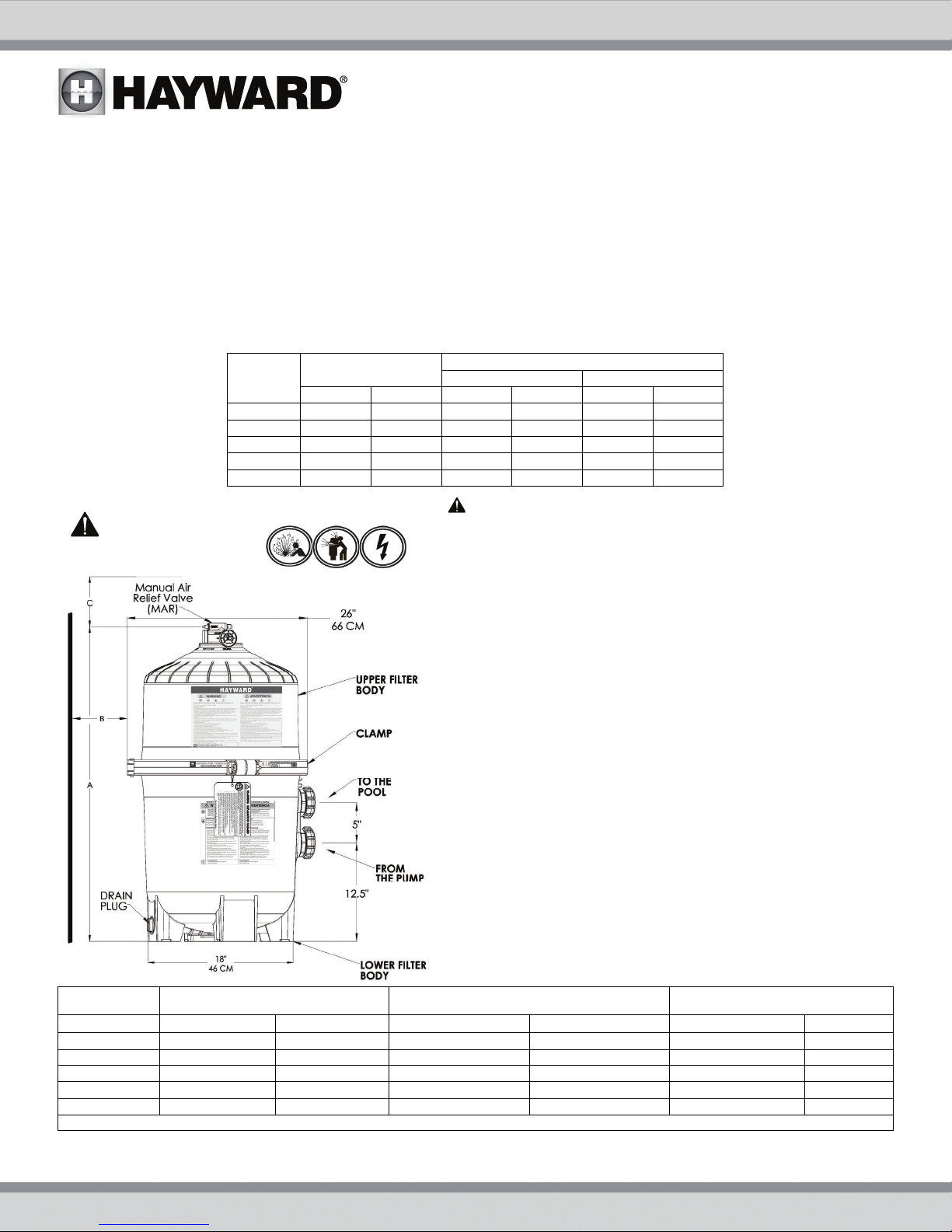
DE7220 52.0 132 18 46 25 63
A
IN CM IN CM IN CM
INSTALLATION
WARNING
Only simple tools (screwdriver and wrenches), plus pipe sealant for
plastic adapters, are required to install and/or service the filter.
1. The filter system should be installed on a
other rigid base. Select a well drained and vented area, one that does
not flood when it rains. Position the filter so that the piping
connections, and winter drain are convenient and accessible for
operation, service, maintenance and winterizing.
2. Position filter so the filter will drain by gravity.
3. If practical, place pump and filter in the shade to shield it from
continuous, direct heat from the sun.
4. Assemble appropriate Filter Control valve (See Page 10 for
selection) to filter. Lubricate the O-ring first (we recommend using
Jack’s 327 Lubricant). Align the two (2) valve pipe connections, with
O-rings in place, with the two openings in the side of the filter tank
and press in firmly. Secure the assembly to the tank connections with
the two bulkhead lock nuts. Do not over-tighten.
5. Connect the pool suction plumbing between the skimmer, pool
outlet and the pump.
6. Install the pool return plumbing.
7. If pressure gauge is not installed, apply Teflon tape to the gauge
threads and carefully screw the gauge into the gauge adapter
assembly.
8. Do not locate pump controls over or near filter.
9. Verify water discharge from the filter manual air relief valve is
directed away from electrical devices
MODEL EFFECTIVE FILTRATION RATE DESIGN FLOW RATE RECOMMENDED AMOUNT OF D.E.
F
DE2420 24 2.2 48 182 3.0 1.4
DE3620 36 3.4 72 273 4.5 2.0
DE4820 48 4.5
DE6020 60 5.6 120 454 7.5 3.4
DE7220 72 6.7 144 545
2
M
MAXIMUM WORKING PRESSURE FOR ALL MODELS 50 PSI (3.45 BAR)
2
GPM LPM LBS KGS
6 363 6.0 2.7
REQUIRED CLEARANCE
“B” SIDE “C” ABOVE
This product should be installed and serviced only by a
qualified professional.
level concrete slab or
.0 4.0
USE ONLY HAYWARD GENUINE REPLACEMENT PARTS 4
 Loading...