

Page 1
ISLS311SX Rev B
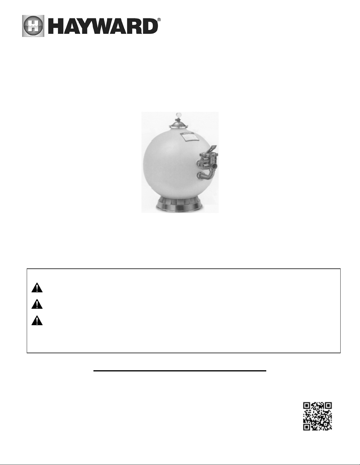
LS Series AQUATIC SAND FILTER
Owner’s Manual
MODELS: LS311SX & LS360SX
IMPORTANT SAFETY INSTRUCTIONS
Basic safety precautions should always be followed, including the following: Failure to follow instructions
can cause severe injury and/or death.
This is the safety-alert symbol. When you see this symbol on your equipment or in this manual, look for
one of the following signal words and be alert to the potential for personal injury.
WARNING warns about hazards that could cause serious personal injury, death or major property
damage and if ignored presents a potential hazard.
CAUTION warns about hazards that will or can cause minor or moderate personal injury and/or property
damage and if ignored presents a potential hazard. It can also make consumers aware of actions that are
unpredictable and unsafe.
The NOTICE label indicates special instructions that are important but not related to hazards.
SAVE THIS INSTRUCTION MANUAL
Hayward Flow Control
One Hayward Industrial Drive
Clemmons, NC 27012-5100
Phone: 1-888-HAY-INDL (1-888-429-4635)
www.haywardflowcontrol.com
Page 2

Table of Contents
1. IMPORTANT SAFETY INSTRUCTIONS ................................................................................................................. 3
2. Introduction .................................................................................................................................................... 4
3. How It Works .................................................................................................................................................. 4
4. Installation ..................................................................................................................................................... 4
5. Initial Start-Up of Filter .................................................................................................................................... 5
6. Filter Control Valve Functions .......................................................................................................................... 6
7. Specifications ................................................................................................................................................. 6
8. Replacement Parts .......................................................................................................................................... 7
USE ONLY HAYWARD GENUINE REPLACEMENT PARTS
Page 2 of 8 LS Series Filter ISLS311SX Rev B
Page 3
1. IMPORTANT SAFETY INSTRUCTIONS
WARNING - Read and follow all instructions in this owner’s manual and on the equipment. Failure to
follow instructions can cause severe injury and/or death.
CAUTION – This FILTER is not intended to be used in swimming pools or spas. It is specifically designed to be
used where bathers are NOT subjected to suction outlets while the pump is in operation.
WARNING – Hazardous Pressure. Water circulation systems operate under hazardous pressure during start up, normal
operation, and after pump shut off. Stand clear of circulation system equipment during pump start up. Failure to follow safety
and operation instructions could result in violent separation of the pump housing and cover, and/or filter housing and clamp due
to pressure in the system, which could cause property damage, severe personal injury, or death. Before water circulation system,
all system and pump controls must be in off position and filter manual air relief valve must be in open position. Before starting
system pump, all system valves must be set in a position to allow system water to return back to the system. Do not change filter
control valve position while system pump is running. Before starting system pump, fully open filter manual air relief valve. Do
not close filter manual air relief valve until a steady stream of water (not air or air and water) is discharged.
WARNING – Separation Hazard. Failure to follow safety and operation instructions could result in violent separation of
pump and/or filter components. Strainer cover must be properly secured to pump housing with strainer cover lock ring. Before
servicing circulation system, filters manual air relief valve must be in open position. Do not operate circulation system if a system
component is not assembled properly, damaged, or missing. Do not operate circulation system unless filter manual air relief is in
fully screwed into filter cap. Never operate or test the circulation system at more than 50 PSI. Do not purge the system with
compressed air. Purging the system with compressed air can cause components to explode, with risk of severe injury or death to
anyone nearby. Use only a low pressure (below 5 PSI), high volume blower when air purging the pump, filter, or piping.
WARNING – Risk of Electric Shock. All electrical wiring MUST be in conformance with applicable local codes, regulations,
and the National Electric Code (NEC). Hazardous voltage can shock, burn, and cause death or serious property damage. To
reduce the risk of electric shock, do NOT use an extension cord to connect unit to electric supply. Provide a properly located
electrical receptacle. Before working on any electrical equipment, turn off power supply to the equipment. To reduce the risk of
electric shock replace damaged wiring immediately. Locate conduit to prevent abuse from lawn mowers, hedge trimmers and
other equipment. Do NOT ground to a gas supply line.
WARNING – Risk of Electric Shock. Failure to ground all electrical equipment can cause serious or fatal electrical shock
hazard. Electrical ground all electrical equipment before connecting to electrical power supply.
WARNING – Risk of Electric Shock. Failure to bond all electrical equipment to system structure will increase risk for
electrocution and could result in injury or death. To reduce the risk of electric shock, see installation instructions and consult a
professional electrician on how to bond all electrical equipment. Also, contact a licensed electrician for information on local
electrical codes for bonding requirements.
WARNING – Risk of Electric Shock . The electrical equipment must be connected only to a supply circuit that is protected by
a ground-fault circuit-interrupter (GFCI). Such a GFCI should be provided by the installer and should be tested on a routine basis.
To test the GFCI, push the test button. The GFCI should interrupt power. Push reset button. Power should be restored. If the GFCI
fails to operate in this manner, the GFCI is defective. If the GFCI interrupts power to the electrical equipment without the test
button being pushed, a ground current is flowing, indicating the possibility of an electrical shock. Do not use this electrical
equipment. Disconnect the electrical equipment and have the problem corrected by a qualified service representative before
using.
USE ONLY HAYWARD GENUINE REPLACEMENT PARTS
Page 3 of 8 LS Series Filter ISLS311SX Rev B
Page 4
2. Introduction
Your Hayward LS Series high-rate sand filter is a high performance, corrosion-proof filter that blends superior
flow characteristics and features with ease of operation. It represents the very latest in high-rate sand filter
technology. It is virtually foolproof in design and operation and when installed, operated and maintained
according to instructions, your filter will produce clear, water with only the least attention and care.
3. How It Works
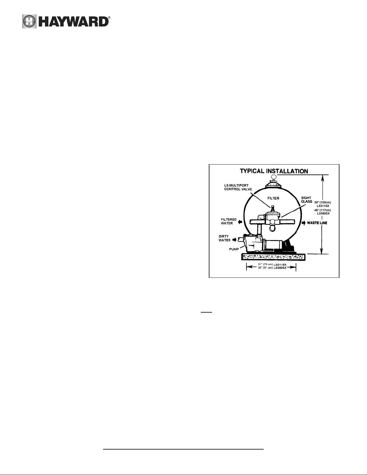
Your filter uses special filter sand to remove dirt particles from the water. Filter sand is loaded into the filter
tank and functions as the permanent dirt removing media. The system water, which contains suspended
dirt particles, is pumped through your piping system and is automatically directed by the patented filter
control valve to the top of the filter tank. As the system water is pumped through the filter sand, dirt particles are trapped by the sand bed, and filtered out. The cleaned system water is returned from the bottom
of the filter tank, through the control valve and back to the system through the piping system. This entire
sequence is continuous and automatic and provides for
total recirculation of system water through your filter and
piping system.
After a period of time, the accumulated dirt in the filter
causes a resistance to flow, and the flow diminishes. This
means it is time to clean (backwash) your filter. With the
control valve in the backwash position, the water flow is
automatically reversed through the filter so that it is
directed to the bottom of the tank, up through the sand,
flushing the previously trapped dirt and debris out the
waste line. Once the filter is backwashed (cleaned) of dirt,
the control valve is manually resequenced to Rinse, and
then Filter, to resume normal filtering.
4. Installation
Only simple tools (screwdriver and wrenches), plus PTFE tape manufactured for plastic adapters, are
required to install and/or service the filter.
1. The filter system should be installed, not more than 6 feet above system water level, on a
slab, very firm ground, or equivalent, as recommended by your dealer. Position the filter so that the
piping connections, control valve, and drain are convenient and accessible for operation, and service.
2. Assemble the filter control valve to filter. Align the two (2) valve pipe connections, with O-rings in place,
with the two openings in the side of the filter tank and press in firmly. Secure the assembly to the tank
connections with the two bulkhead locknuts.
3. Loading sand media. Filter sand media is loaded through the top opening of the filter.
a. Remove the top diffuser from the internal diffuser elbow pipe and place flexible, automatic air relief
tube to the side, out of the way, inside the tank.
b. Cap the internal diffuser elbow pipe with the sand shield provided to prevent sand from entering it.
c. It is good practice to fill tank approximately 1/2 way with water to provide a cushioning effect when
the filter sand is poured in. This helps protect the under-drain laterals from excessive shock. (Be sure
the drain cap is securely in place on drain pipe.)
Note: Confirm all laterals are in the down position before loading with sand. (See Diag A on Page 7.)
d. Carefully pour in correct amount and grade of filter sand, as specified. Sand surface should be leveled
and should come to about 6” from the top of the filter tank. Use no more than the recommended
amount of sand.
Do not overtighten.
level
concrete
USE ONLY HAYWARD GENUINE REPLACEMENT PARTS
Page 4 of 8 LS Series Filter ISLS311SX Rev B
Page 5
e. Remove the sand shield from internal diffuser elbow pipe.
f. Replace diffuser on internal diffuser elbow pipe, positioning automatic air relief tube through the hole
provided in the diffuser.
g. Wipe filter flange clean.
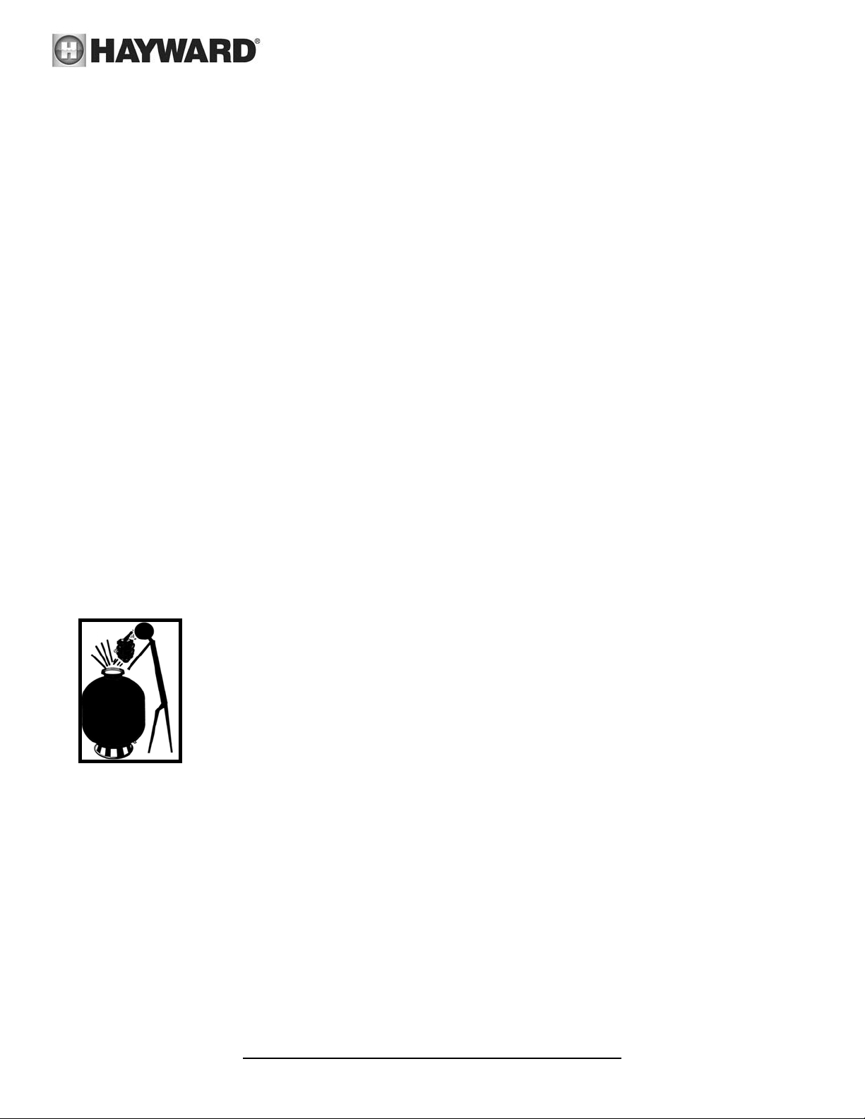
h. Insert top closure dome (with flange O-ring in place) into the tank neck. Place clamp around dome
flange and tank flange and tighten with screwdriver, tapping around clamp with screwdriver handle to
help seat flange clamp.
Do not overtighten
4. Connect pump to control valve opening marked PUMP according to instructions. Make return to system
pipe connection to control valve opening marked RETURN and complete other necessary plumbing
connections, suction lines to pump, waste, etc.
5. Make electrical connections to pump per pump instructions.
6. To prevent water leakage, be sure drain cap is securely in place and all pipe connections are tight.
.
5. Initial Start-Up of Filter
1. Be sure correct amount of filter sand media is in tank and that all connections have been made and are
secure.
IMPORTANT: To prevent unnecessary strain on piping system and valving, always shut off pump before
switching Filter Control Valve positions.
2. Depress LS control valve handle and rotate to BACKWASH* position. (To prevent damage to control valve
seat, always depress handle before turning.)
3. Prime and start pump according to pump instructions. (be sure all suction and return lines are open),
allowing the filter tank to fill with water.
WARNING– All suction and discharge valves must be open when starting the system. Failure
to do so could cause severe personal injury and/or property damage.
4. Once water flow is steady out the waste line, run the pump for at least 2 minutes. This initial backwashing
of the filter is recommended to remove any impurities or fine sand particles in the sand media.
5. Turn pump off and set LS valve to RINSE position. Start pump and operate until water in sight glass is
clear—about 1/2 to 1 minute. Turn pump off, set valve to FILTER position and
restart pump. Your filter is now operating in the normal filter mode, filtering
particles from the system water.
6. Adjust system suction and return valves to achieve desired flow. Check system
and filter for water leaks and tighten connections, bolts, nuts, as required.
7. Note the initial pressure gauge reading when the filter is clean. (It will vary from
system to system depending upon the pump and general piping system.) As the
filter removes dirt and impurities from the system water, the accumulation in the
noted, it is time to backwash (clean) the filter (see BACKWASH under Filter Control Valve Functions).
filter will cause the pressure to rise and flow to diminish. When the pressure gauge
reading is 6-8 PSI (0.41-0.55 BAR) higher than the initial "clean" pressure you
NOTE: During initial clean-up of the system water it may be necessary to backwash
frequently due to the unusually heavy initial dirt load in the water.
To prevent damage to the pump and filter and for proper operation of the system, clean pump strainer
regularly.
USE ONLY HAYWARD GENUINE REPLACEMENT PARTS
Page 5 of 8 LS Series Filter ISLS311SX Rev B
Page 6

2
6. Filter Control Valve Functions
FILTER — Set valve to FILTER for normal filtering. Also use for regular vacuuming.
BACKWASH — For cleaning filter. When filter pressure gauge rises 8-10PSI (0.55-0.69 BAR) above
start-up (clean pressure): Stop the pump, set valve to BACKWASH. Start pump and backwash until
water in sight glass is clear. Proceed to RINSE.
RINSE — After backwashing, with pump off, set valve to RINSE. Start pump and operate for about 1/2 to
1 minute. This ensures that all dirty water from backwashing is rinsed out to the filter to waste,
preventing possible return to the system. Stop pump, set valve to FILTER, and start pump for normal
filtering.
WASTE — To bypass filter for draining or lowering water level and for vacuuming heavy debris directly
to waste.
RECIRCULATE — Water is recirculated through the system, bypassing the filter.
CLOSED — Shuts off flow from pump to filter.
VACUUMING — Vacuuming can be performed directly into the filter. When vacuuming heavy debris
loads, set valve to WASTE position to bypass the filter and vacuum directly out to waste.
WINTERIZING
1. Completely drain tank by unscrewing drain cap at base of filter tank. Leave cap off during winter.
2. Depress the LS control valve handle and rotate so as to set pointer on valve top between any two positions.
This will allow water to drain from the valve. Leave valve in this "inactive" position.
3. Drain and winterize pump according to pump instructions.
7. Specifications
EFFECTIVE
MODEL
NUMBER
LS311SX 5.0 .46 50 3.45 18 460 18 460 0.45-0.55mm 350 160
LS360SX 6.7 .62 50 3.45 18 460 18 460 0.45-0.55mm 700 318
Table 1 **Also known as No. 20 Silica Sand
FILTRATION
AREA
FT2 M
MAXIMUM
WORKING
PRESSURE
PSI BAR INCH MM INCH MM FILTER
REQUIRED CLEARANCE MEDIA REQUIRED
SIDE ABOVE TYPE AMOUNT
SAND**
LBS KG
USE ONLY HAYWARD GENUINE REPLACEMENT PARTS
Page 6 of 8 LS Series Filter ISLS311SX Rev B
Page 7
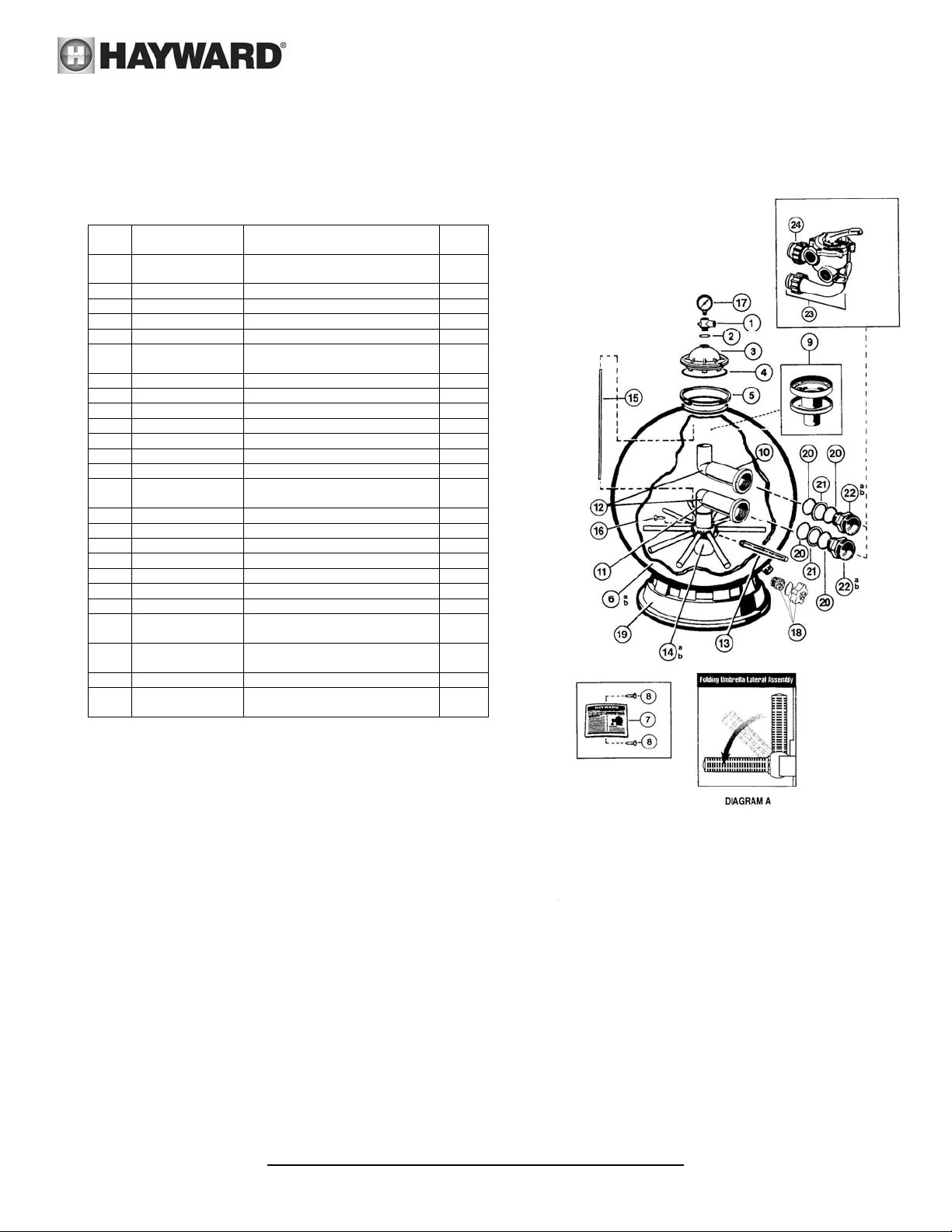
8. Replacement Parts
PARTS LISTING
LS311SX LS360SX
REF
NO
1 DEX2400S Relief Valve/Gauge Adapter
2 SX200Z5 O-Ring, 13/16” O.D. 1
3 SX244K Top Closure Dome 1
4 GMX600F Valve/tank o-ring 1
5 LSX310N Flange Clamp, 316 stainless 1
6a
6b
7 SX311G Label Plate with Label 1
8 LSX311Z1S Label Plate Screws 316 SSTL 1
9 SX244G Top Diffuser 1
10 LSX311CD1FW Top Elbow Assy (LS311SX) 1
11 LSX311CD2FW Bottom Elbow Assy (LS311SX) 1
12 LSX360CDFW Elbow Assy (LS360SX) 2
13 SX310HN Lateral (One piece) 10
14 LSX311DA
15 CX1100Z4 Plastic Air Tube 1
16 LSX200Z2S Air Tube Lock Screw 316 SSTL 1
17 LSXGAUGE Pressure Gauge 2 ½” 316 SSTL 1
18 SX180LA Drain Cap Assy 1
19 SX310J Filter Stand Support 1
20 SX360Z1 O-Ring 4
21 SX360E O-Ring Spacer 2
22 SX244P
23 LSP715X62 2” LS Control Valve Assembly
24 SX200Z4 O-Ring 2
DEX2400Z3A O-Ring for Air Relief valve stem
PART
NO.
SX311A2FW
SX360AA2FW
LSX242MA3
SX311F
DESCRIPTION NO.
Assy
Filter Tank w/Base (LS311SX)
Filter Tank w/Base (LS360SX)
Lateral Holder Assy (LS311SX)
Lateral Holder Assy (LS360SX)
Bulkhead Fitting (S311SX)
Bulkhead Fitting (S360SX)
without Gauge
(Set of 3)
REQ
1
1
1
1
1
2
2
1
USE ONLY HAYWARD GENUINE REPLACEMENT PARTS
Page 7 of 8 LS Series Filter ISLS311SX Rev B
Page 8
ISLS311SX Rev B
is a registered trademark of Hayward Industries, Inc.
2014 Hayward Industries. All rights reserved.
 Loading...