

HAYWARD LPCUS11xxx, LPCUN11xxx User Manual
092467 RevA
Universal
ColorLogic® and CrystaLogic
LED Light Fixtures
Installation and Operation Manual
TM
Contents
Safety Instructions..........2
Introduction....................3
Installation.....................4
Replacement Parts.........11
Operation......................12
Troubleshooting............13
Warranty........................14
Registration Card...........15
LPCUS11xxx, LPCUN11xxx
LSCUS11xxx, LSCUN11xxx
LPLUS11xxx, LSLUS11xxx
LPWUS11xxx
Pour obtenir le manuel de l’usager
en Francais consultez www.hayward-pool.ca.
Hayward Pool Products
620 Division Street, Elizabeth NJ 07207
www.hayward.com
USE ONLY HAYWARD GENUINE REPLACEMENT PARTS

IMPORTANT SAFETY INSTRUCTIONS
SAFETY WARNING: Do not open. Light has no user serviceable parts inside. Im-
proper installation may result in death or serious injury to bathers or service personnel
or others by way of electric shock. Disconnect electrical power before installing or
servicing this equipment. Read and follow all instructions. This product to be installed
by qualied personnel only.
INSTALLATION DEPTH REQUIREMENT: Except when the xture is installed in an
area of the swimming pool that is not used for swimming and the lens is adequately
guarded to keep any person from contacting it, the xture shall be in installed in or on
a wall of the pool, with the top of the lens opening not less than 4 in. and no more than
72 in. below the normal water level of the pool.
IMPORTANT WIRING CHECKLIST
Do not skip any steps in this or any section of the manual.
The above safety warnings and the complete installation instructions in this manual have been read and fol-
lowed.
A SAFETY LISTED POOL/SPA ISOLATION TRANSFORMER HAS BEEN USED TO SUPPLY 14 VOLTS TO
THE FIXTURE.
The transformer output wiring HAS NOT been tied or shorted to ground.
The cord length has not been extended beyond the guidelines in this manual.
The cord jacket is not damaged, cut or spliced except as noted below.
Extensions or splices to the cord are only made in a safety listed Pool / Spa junction box or junction box trans-
former system.
The luminaire is rmly secured to the niche and cannot be removed without the use of a tool.
The niche is properly bonded UNLESS a Hayward Universal ColorLogic Niche is used.
The luminaire has been installed by qualied personnel in compliance with the National Electrical Code (NEC)
or Canadian Electric Code (CE Code) and any applicable local codes and/or regulations.
Installed by: ______________________ of company ____________________________ Date: __________________
LEAVE THESE INSTRUCTIONS WITH PROPERTY OWNER
2
USE ONLY HAYWARD GENUINE REPLACEMENT PARTS

Introduction
Congratulations on your purchase of a Hayward® Universal ColorLogic®/CrystaLogicTM LED Light. Welcome to a more colorful world brought to you by
Hayward that generates colored light and effects using a microprocessor to control red, green, blue, and white LED’s.
Your Hayward Universal ColorLogic/CrystaLogic underwater pool or spa light has these special features:
1. Long-lasting LED’s (light-emitting diodes) which can last up to 10 times longer than current incandescent or halogen pool and spa lights.
2. Multicolor capability without any color wheels or moving parts to wear out.
3. Multi color program capability which allows you to select any one of 17 different programs, 10 fixed colors, and 7 color shows in stand-alone mode.
4. When networked with a Hayward Pro Logic® pool/spa controller, Universal ColorLogic lights (LSCUN11xxx and LPCUN11xxx) are capable of 4 additional shows, 101 fixed light colors and offer custom speed, brightness and motion control.
5. Offers spectacular brilliant light with low power consumption. Uses up to 86% less energy than a typical incandescent pool light.
The 12 volt Hayward Universal ColorLogic and CrystaLogic LED (light-emitting diode) underwater lighting fixtures you have purchased are UL Listed to be
installed in all Hayward or any other manufacturer’s light fixture housing (niche).
Installation of light and niche must be in accordance with Article 680 of the National Electrical Code (NEC) and any applicable local codes. Ensure that your
niche is properly grounded and bonded. NOTE: the Hayward LFGUY1000 low profile, all plastic niche does not require bonding or grounding.
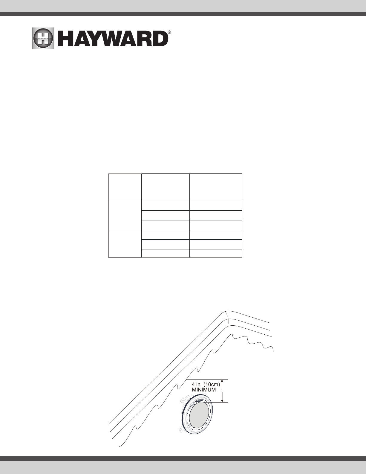
Because of the all plastic design with an impact resistant lens, these lights can be installed as little as 4 inches (10cm) from below the normal water level
of the pool or spa to the top of the lens. It can also be installed upward facing without a rock guard for lighting ponds, fountains, or water falls.
Important Note When Installing LFGUY1000 Niches in Concrete/Gunite Pools:
LFGUY1000 Niche: A gunite/plaster shield is provided to protect the niche and ring during construction. The shield is designed to be installed during the
gunite and plastering process. When finished guniting, pull on the tab and remove the outer ring of the shield. Keep the shield in place while plastering
and until the light is ready to be installed.
GIVE THESE INSTRUCTIONS TO POOL/SPA OWNER AFTER INSTALLATION
USE ONLY HAYWARD GENUINE REPLACEMENT PARTS
3
Installation
Product
Total Cord Length
from Transformer
to Light
12v Universal
ColorLogic
Pool Light
12v Universal
ColorLogic
Spa Light
Minimum Required
Voltage at
Transformer
30 ft
50 ft
100 ft
30 ft
50 ft
100 ft
12 - 14 volts
12 - 14 volts
13 - 14 volts
13 - 14 volts
14 volts
14 volts
If replacing an existing light, remove power to the light at the panel before starting this installation. Installation must be performed in accordance with Local
and NEC codes.
Cord Length and Minimum Required Voltage
When installing Universal ColorLogic/CrystaLogic low voltage lights, the length of the cord has an effect on performance. To prevent performance problems,
verify the transformer is providing the minimum required voltage according to the table below. To check this voltage, measure the voltage at the transformer
while the light is “on” and operating in “white” mode. In some cases, a voltage greater than 12 volts is required due to a long cord run. Some transformers
provide higher voltage taps for this purpose; check your transformer manufacturer’s installation instructions for details. When using Hayward or other transformers that offer a 14v option, we suggest that you always use the 14 volt tap.
4
Install Niche (new installations)
NOTE: For installation of Hayward niches, see installation instructions provided with the unit. The light fixture must be installed in or on a wall of
the pool or spa with the top of the lens not less than 4 inches (10 cm) below the normal water level of the pool except when the fixture is installed in an area
of the swimming pool that is not used for swimming. Select a location for the light fixture(s) that will give optimum light dispersion for the pool or spa design.
Be sure to consider the direction of emitted light and take care not to point lights directly at the house or outdoor living spaces.
USE ONLY HAYWARD GENUINE REPLACEMENT PARTS
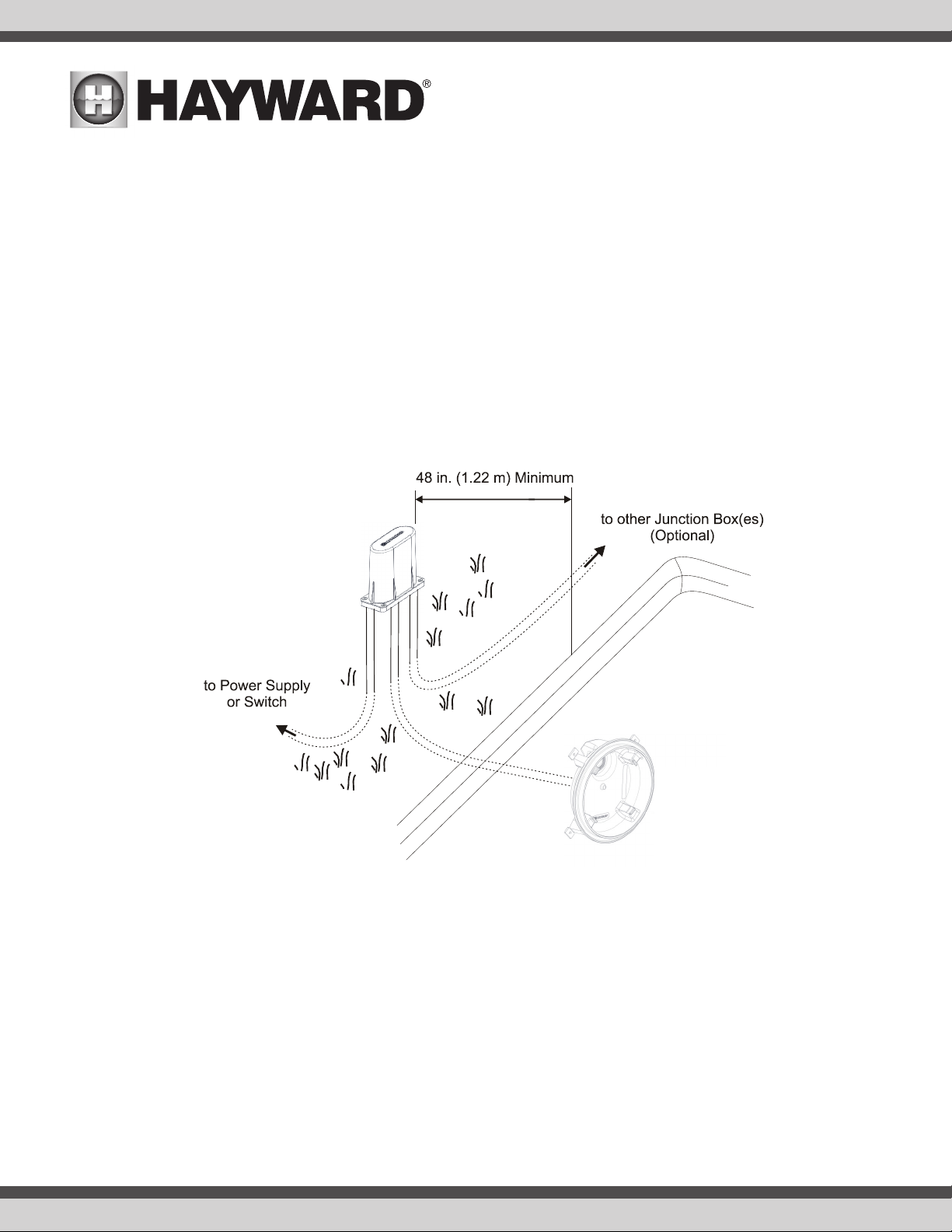
Install Junction Box or Junction Box Transformer
When using a wallmount low voltage transformer, a junction box should be installed to make the connection to the pool/spa light. If using more than
one light, an adequate amount of junction boxes must be installed. Alternatively, Hayward low voltage junction box transformer kits (LTBUY11H65) can
be used when in-line transformers are desired. Refer to page 9 for more information.
Junction boxes must be installed not less than 48 inches (1.22 m) from the edge of the pool or spa. Run conduit from the niche up to the junction box
such that the junction box is not less than 8 inches (20 cm) above the maximum pool or spa water level, or not less than 4 inches (10 cm) above the
ground, whichever is greater. Additional conduit should be run from the junction box to the power supply, switch panel, pool/spa controller, etc.
USE ONLY HAYWARD GENUINE REPLACEMENT PARTS
5
 Loading...