

Hayward LifeStar VS Owner's Manual
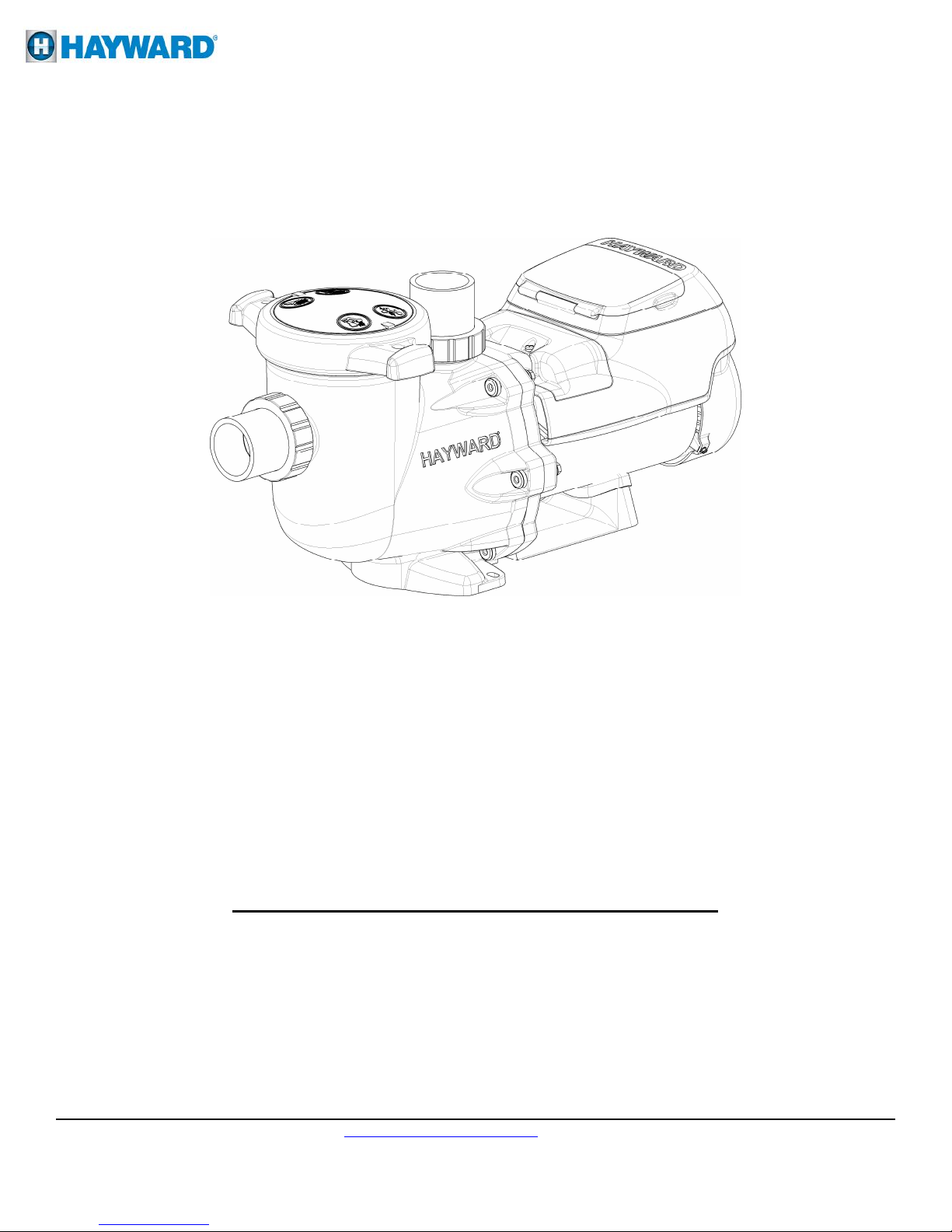
LifeStar
Owner’s Manual
®
VS
Hayward LifeStar® VS is the Aquatic Industry’s most energy efficient variable speed pump. The totally
enclosed, permanent magnet motor combined with its advanced hydraulic design provides unparalleled energy
savings. LifeStar® VS is easily installed either as a programmable stand-alone pump or with a Hayward or
third party controller and features an easy-to-use digital control interface that can be mounted in four different
positions on the pump or removed and mounted on the wall for total user convenience.
NOTE - To prevent potential injury and to avoid unnecessary service calls, read this manual carefully and
completely.
SAVE THIS INSTRUCTION MANUAL
USE ONLY HAYWARD GENUINE REPLACEMENT PARTS
_____________________________________________________________________________________
Hayward Flow Control www.haywardflowcontrol.com 1-888-HAY-INDL (1-888-429-4635)
LSVSIOM Rev A 12/08/14
Pg. 1of 36

Table of Contents
1. IMPORTANT SAFETY INSTRUCTIONS …………………………………………………………. 3
2. General Information ………………………………………………………………………………….. 6
2.1. Introduction 6
2.2. Primary Features 6
2.3. Product Dimensions 6
3. Energy Efficiency Overview ………………………………………………………………………... 7
4. Installation and Wiring ……………………………………………………………………………… 7
4.1. Pump Location 7
4.2. Pump Mounting 8
4.3. Pipe Sizing Chart 8
4.4. Plumbing 8
4.5. Electrical 9
4.6. Electrical Specs 9
4.7. Voltage 9
4.8. Grounding and Bonding 9
4.9. Wiring 10
4.10. Remote Control Wiring / Operation 10
4.11. Digital Control Interface Orientation 11
4.12. Interface Wall Mounting 11
5. Wiring Diagrams …………………………………………………………………………………… 14
5.1. Input Power/Motor Wiring (Required) 14
5.2. Wall Mounted Digital Control Interface Wiring (Optional) 14
5.3. Hayward Control Wiring (For remote control of pump speed) 15
5.4. External Relay Speed Control Wiring (For remote selection of pump speed) 16
5.5. Remote Stop Switch Wiring (Optional) 17
6. Startup & Operation ………………………………………………………………………………… 17
6.1. Prior to Start-Up 17
6.2. Starting/Priming the Pump 17
6.3. User Interface Summary 19
6.4. Menu Outline 20
LifeStar® VS Password Protection 21
6.5. Initial Startup 22
6.6. Configuration Menu 22
6.7. Timer Menu 24
6.8. Preset Speed Setup Menu 25
6.9. Diagnostic Menu 26
6.10. Stop/Resume 27
6.11. Quick Clean 27
6.12. Remote Stop 28
7. Maintenance …………………………………………………………………………………………. 28
8. Storage ………………………………………………………………………………………………. 28
8.1. Storing Pump for Winterization 29
9. Shaft Seal Change Instructions ……………………………………………………………………… 29
9.1. Removing the Motor Assembly 29
9.2. Removing the Impeller 29
9.3. Removing the Ceramic Seat 30
9.4. Seal Installation 30
9.5. Replacing the Impeller and Diffuser 30
9.6. Replacing the Motor Assembly 30
10. Replacement Parts ………………………………………………………………………………….. 31
10.1. Parts Diagram 32
10.2. Parts Listing 32
11. Troubleshooting ……………………………………………………………………………………. 33
11.1. General Problems 34
11.2. Check System Messages 35
12. Warranty …………………………………………………………………………………………… 36
USE ONLY HAYWARD GENUINE REPLACEMENT PARTS
_____________________________________________________________________________________
Hayward Flow Control www.haywardflowcontrol.com 1-888-HAY-INDL (1-888-429-4635)
IS3401VSPFC Rev A 12/08/14
Pg. 2 of 36
1. IMPORTANT SAFETY INSTRUCTIONS
Before installing or servicing this electrical equipment, turn the power supply OFF.
Basic safety precautions should always be followed, including the following: Failure to follow instructions
may result in injury.
This is the safety-alert symbol. When you see this symbol on your pump or in this manual, look for
one of the following signal words, and be alert to the potential for personal injury.
WARNING warns about hazards that could cause serious personal injury, death or major property
damage and if ignored presents a potential hazard.
CAUTION warns about hazards that will or can cause minor or moderate personal injury and/or
property damage and if ignored presents a potential hazard. It can also make consumers aware of actions
that are unpredictable and unsafe.
The NOTICE label indicates special instructions that are important but not related to hazards.
WARNING – Read and follow all instructions in this owner’s manual and on the equipment.
Failure to follow instructions can cause severe injury and/or death.
WARNING – This product should be installed and serviced only by a qualified professional.
CAUTION – All electrical wiring MUST be in conformance with all applicable local codes,
regulations, and the National Electric Code (NEC).
USE OF NON-HAYWARD REPLACEMENT PARTS VOIDS WARRANTY.
ATTENTION INSTALLER - THIS MANUAL CONTAINS IMPORTANT INFORMATION
ABOUT THE INSTALLATION, OPERATION, AND SAFE USE OF THIS VARIABLE SPEED
PUMP THAT MUST BE FURNISHED TO THE END USER OF THIS PRODUCT. FAILURE
TO READ AND FOLLOW ALL INSTRUCTIONS COULD RESULT IN SERIOUS INJURY.
WARNING – To reduce risk of injury, do not permit children to use or climb on this product.
CAUTION – This product is designed for indoor and outdoor use. If used outdoors, it is strongly
advised to protect the electrical components from the weather. Select a well-drained area, one that will
not flood when it rains. It requires free circulation of air for cooling. Do not install in a damp or nonventilated location. If installed within an outer enclosure or beneath, adequate ventilation and free
circulation of air must be provided to prevent overheating of the motor.
USE ONLY HAYWARD GENUINE REPLACEMENT PARTS
_____________________________________________________________________________________
Hayward Flow Control www.haywardflowcontrol.com 1-888-HAY-INDL (1-888-429-4635)
IS3401VSPFC Rev A 12/08/14
Pg. 3 of 36
WARNING – Components (seals, gaskets, etc.) have a finite life. All components should be
inspected frequently and replaced at least every ten years, or if found to be damaged, broken, cracked,
missing, or not securely attached.
WARNING – Risk of Electric Shock. All electrical wiring MUST be in conformance with
applicable local codes, regulations, and the National Electric Code (NEC). Hazardous voltage can
shock, burn, and cause death or serious property damage. To reduce the risk of electric shock, do NOT
use an extension cord to connect unit to electric supply. Provide a properly located electrical receptacle.
Before working on pump or motor, turn off power supply to the pump.
WARNING – To reduce the risk of electric shock replace damaged wiring immediately.
WARNING – Risk of Electric Shock. In accordance with the National Electric Code (NEC),
connect only to a branch circuit protected by a ground-fault circuit-interrupter (GFCI). Contact a
qualified electrician if you cannot verify that the circuit is protected by a GFCI. The unit must be
connected only to a supply circuit that is protected by a ground-fault circuit-interrupter (GFCI). Such a
GFCI should be provided by the installer and should be tested on a routine basis. To test the GFCI, push
the test circuit button. The GFCI should interrupt power. Push the reset button. Power should be
restored. If the GFCI fails to operate in this manner, the GFCI is defective. If the GFCI interrupts
power to the pump without the test button being pushed, a ground current is flowing, indicating the
possibility of an electric shock. Do not use this pump. Disconnect the pump and have the problem
corrected by a qualified service representative before using.
WARNING – Failure to bond pump to the structure will increase risk for electrocution and could
result in injury or death. To reduce the risk of electric shock, see installation instructions and consult a
professional electrician on how to bond pump. Also, contact a licensed electrician for information on
local electrical codes for bonding requirements.
Notes to electrician: Use a solid copper conductor, size 8 or larger. Run a continuous wire from
external bonding lug to reinforcing rod or mesh. Connect a No. 8 AWG (8.4 mm2) [No. 6 AWG (13.3
mm2) for Canada] solid copper bonding wire to the pressure wire connector provided on the pump
housing and to all metal parts of the structure, and to all electrical equipment, metal piping (except gas
piping), and conduit within 5 ft. (1.5 m) of inside walls of the structure(s). IMPORTANT - Reference
NEC codes for all wiring standards including, but not limited to, grounding, bonding and other general
wiring procedures.
WARNING – Suction Entrapment Hazard. Suction in suction outlets and/or suction outlet
covers, which are damaged, broken, cracked, missing, or unsecured cause severe injury and/or death due
to the following entrapment hazards.
USE ONLY HAYWARD GENUINE REPLACEMENT PARTS
_____________________________________________________________________________________
Hayward Flow Control www.haywardflowcontrol.com 1-888-HAY-INDL (1-888-429-4635)
IS3401VSPFC Rev A 12/08/14
Pg. 4 of 36
WARNING – Hazardous Pressure. Water circulation systems operate under hazardous pressure
during start-up, normal operation, and after pump shut-off. Stand clear of circulation system equipment
during pump start-up. Failure to follow safety and operation instructions could result in violent
separation of the pump housing and cover due to pressure in the system, which could cause property
damage, severe personal injury, or death. Before servicing the water circulation system, all system and
pump controls must be in off position and filter manual air relief valve must be in open position. Before
starting pump, all system valves must be set in a position to allow system water to return back to the
water source. Do not change filter control valve position while pump is running. Before starting pump,
fully open filter manual air relief valve. Do not close filter manual air relief valve until a steady stream
of water (not air or air and water mix) is discharged from the valve. All suction and discharge valves
MUST be OPEN when starting the circulation system. Failure to do so could result in severe personal
injury and/or property damage.
WARNING – Separation Hazard. Failure to follow safety and operation instructions could result in
violent separation of pump components. Strainer cover must be properly secured to pump housing with
strainer cover lock ring. Before servicing the circulation system, all system and pump controls must be
in off position and filter manual air relief valve must be in open position. Do not operate the circulation
system if a system component is not assembled properly, damaged, or missing. Do not operate the
circulation system unless filter manual air relief valve body is in locked position in filter upper body.
All suction and discharge valves MUST be OPEN when starting the circulation system. Failure to do so
could result in severe personal injury and/or property damage.
WARNING – Never operate the circulation system at more than 50 PSI maximum.
WARNING – Fire and burn hazard. Motors operate at high temperatures and if they are not
properly isolated from any flammable structures or foreign debris they can cause fires, which may cause
severe personal injury or death. It is also necessary to allow the motor to cool for at least 20 minutes
prior to maintenance to minimize the risk for burns.
WARNING – Failure to install according to defined instructions may result in severe personal
injury or death.
USE ONLY HAYWARD GENUINE REPLACEMENT PARTS
_____________________________________________________________________________________
Hayward Flow Control www.haywardflowcontrol.com 1-888-HAY-INDL (1-888-429-4635)
IS3401VSPFC Rev A 12/08/14
Pg. 5 of 36
2. General Information
2.1. Introduction
This manual contains information for the proper installation and operation of the Hayward LifeStar®
Variable Speed Pump. The instructions in this manual MUST be followed precisely.
2.2. Primary Features
Totally enclosed, permanent magnet motor
Advanced hydraulic design
Fully programmable with a self-contained 24-hour clock and up to 8 custom speed and timer
functions
For enhanced management, the LifeStar® VS can be controlled by Hayward or third party control
platforms without the need for additional accessories
Digital control interface that can be mounted in four different positions on the pump or removed and
mounted on the wall
No-rib, extra-large basket design ensures easy debris removal and extends time between cleanings
Motor drive includes built-in protection for high temperatures and voltage fluctuations. Drive is also
designed to withstand temperatures below freezing without issue
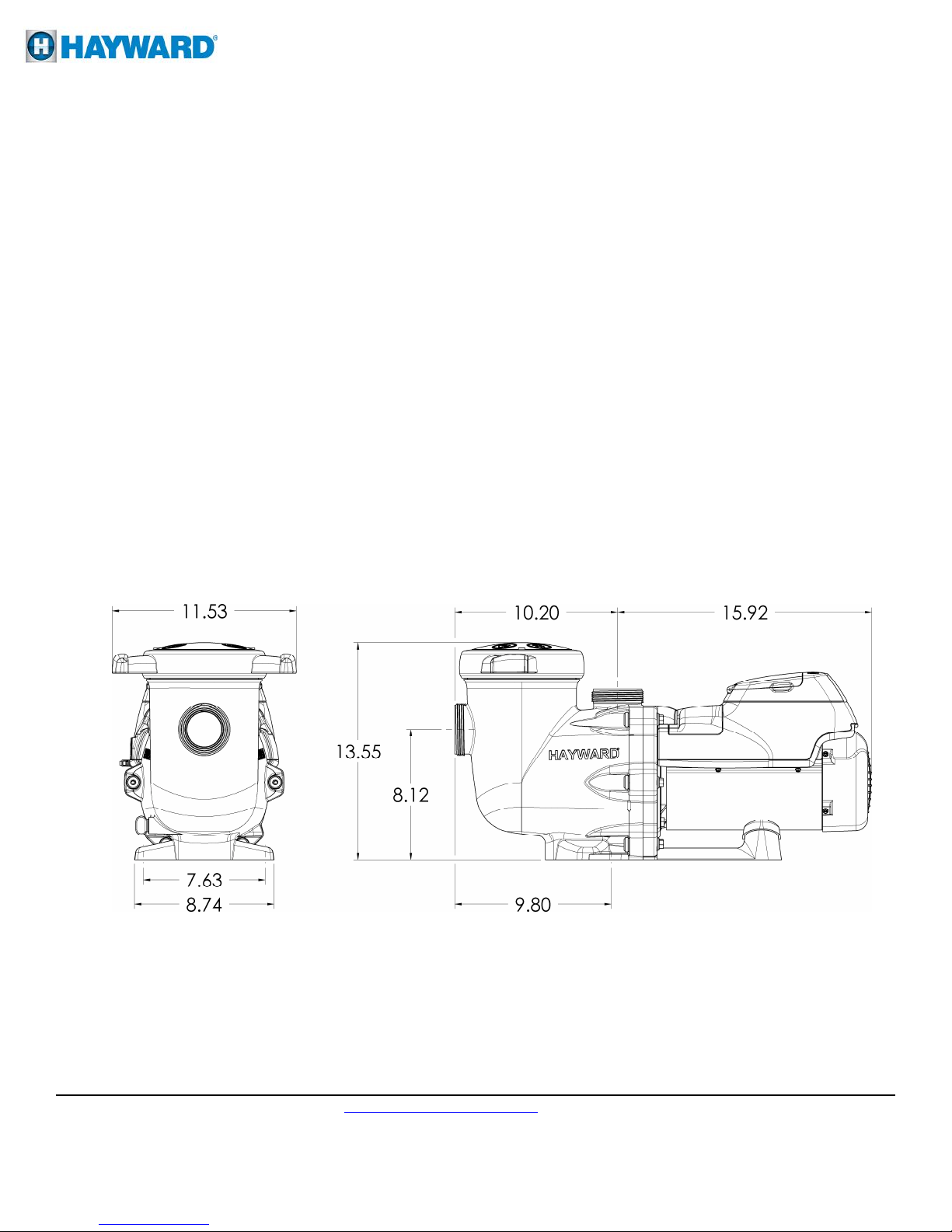
2.3. Product Dimensions
USE ONLY HAYWARD GENUINE REPLACEMENT PARTS
_____________________________________________________________________________________
Hayward Flow Control www.haywardflowcontrol.com 1-888-HAY-INDL (1-888-429-4635)
IS3401VSPFC Rev A 12/08/14
Pg. 6 of 36
3. Energy Efficiency Overview
The energy consumed by a pump is measured in terms of Watts (W) or Kilowatts (kW). The LifeStar®
Variable Speed Pump displays power consumption in Watts. Given this information, you can determine the
cost of operating the pump:
Power consumption of pump X Cost of electricity = Cost of Pump Operation per Hour
Example: LifeStar® Variable Speed Pump operating at 300 W. Cost of electricity = $0.10 per kWh
Convert Watts to Kilowatts: 300 W = 0.3 kW
0.3 kW X $0.10/kWh = $0.03 per hour
Note the power consumption is greatly affected by the speed of the pump. Lowering the speed of the pump
can drastically reduce the power that is consumed. Below are some of the major benefits of running the
pump at lower speeds.
Benefits of running at low speeds
Save electricity and money
Improved filtration – the filter can often remove smaller particles when the water moves slower
Quiet operation
Reduced Total Dynamic Head – less stress on equipment (e.g. filter) which can lengthen equipment life
When determining the speed(s) to operate your pump, you must also take into account the minimum
requirements for proper sanitation and equipment/water feature functionality.
It is recommended you filter (“turnover”) all the water according to the schedule set by the Life Support
Manager. Running the pump at a lower speed may require running the pump for a longer period of time in
order to meet the turnover requirements for proper sanitation.
After setting the pump speed(s), it is recommended you check that all other equipment/water features are
functioning as intended. For example, when running at a low speed for daily filtration, verify water is
adequately flowing. Operate the pump at higher speeds for the shorter periods of time needed to operate a
heater, water feature, etc.
4. Installation and Wiring
WARNING – This product should be installed and serviced only by a qualified professional.
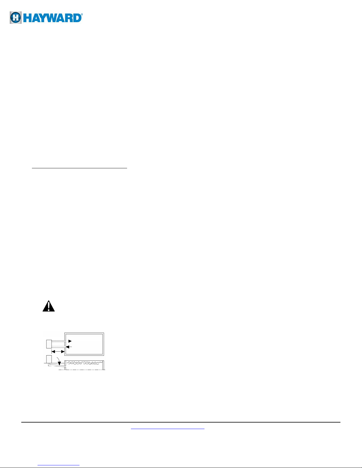
4.1. Pump Location
Locate pump as close to the water source as practical and run suction lines as
direct as possible to reduce friction loss. Suction lines should have continuous
slope upward from lowest point in line. Joints must be tight (but not overtightened). Suction line diameter must equal or be larger than the discharge line
diameter. Though the pump is designed for indoor or outdoor use, it is advised
to place pump in an outdoor application in the shade to shield them from
continuous direct heat. Select a well-drained area that will not flood when it rains. Do NOT install
pump and filter in a damp or non-ventilated location. Keep motor clean. Pump motors require free
circulation of air for cooling.
USE ONLY HAYWARD GENUINE REPLACEMENT PARTS
_____________________________________________________________________________________
Hayward Flow Control www.haywardflowcontrol.com 1-888-HAY-INDL (1-888-429-4635)
IS3401VSPFC Rev A 12/08/14
Pg. 7 of 36
MAXIMUM RECOMMENDED SYSTEM FLOW RATE BY
Minimum Straight
Pipe Length “L” in.
4.2. Pump Mounting
Install pump on a level concrete slab or other rigid base to meet all local and national codes. Secure
pump to base with screws or bolts to further reduce vibration and stress on pipe or hose joints. The base
must be level, rigid, and vibration free.
Pump mount must:
Allow pump inlet height to be as close to water level as possible.
Allow use of short, direct suction pipe (to reduce friction losses).
Allow for valves in suction and discharge piping.
Be protected from excess moisture and flooding.
Allow adequate access for servicing pump and piping.
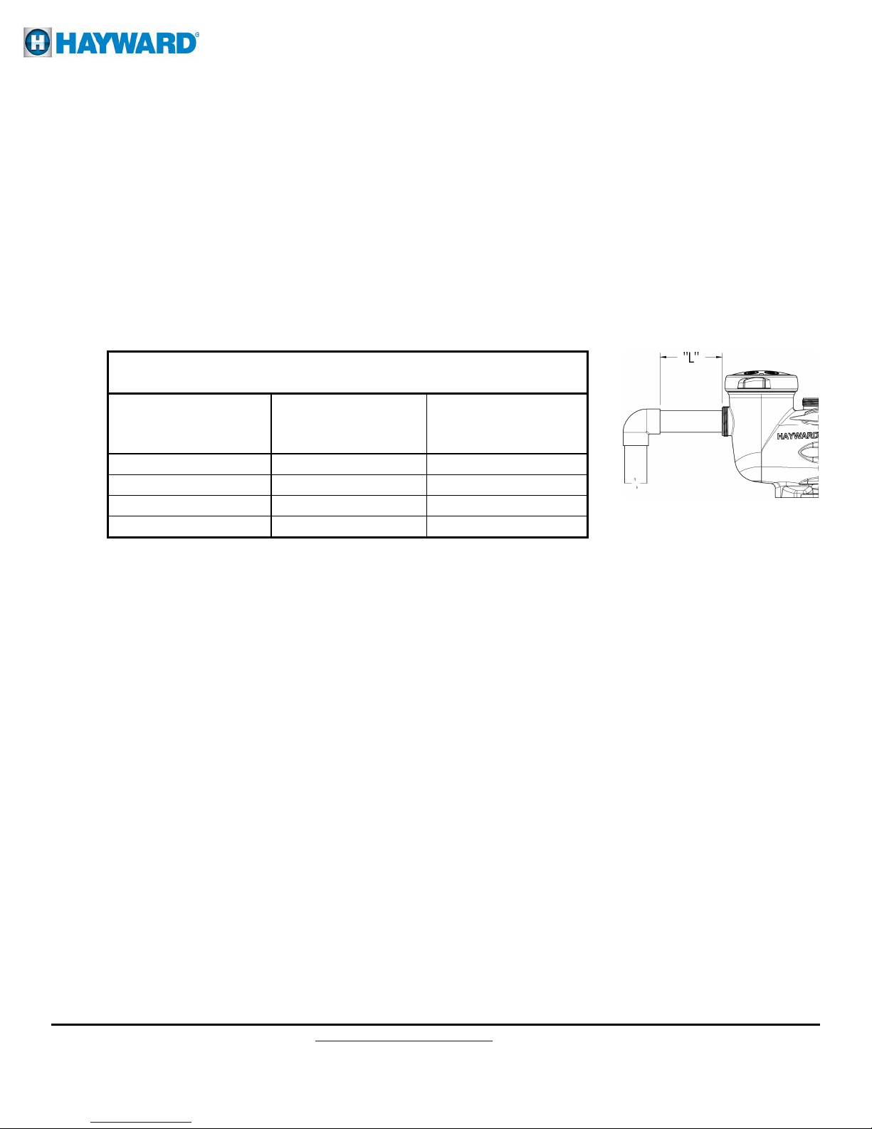
4.3. Pipe Sizing Chart
PIPE SIZE
Pipe Size
in. [mm]
Maximum Flow Rate
GPM [LPM]
[mm] *
1 ½” [50] 45 [170] 7 ½” [190]
2” [63] 80 [300] 10” [254]
2 ½” [75] 110 [415] 12 ½” [317]
3” [90] 160 [600] 15” [381]
* Note: It is recommended that a minimum length of straight piping (shown as “L” in above diagram),
equivalent to 5 pipe size diameters, be used between the pump suction inlet and any plumbing fittings
(elbows, valves, etc.).
When installing the LifeStar® VS, care should be taken to ensure proper pipe and equipment
sizing to handle the maximum flow required. It is recommended to set the maximum speed in
order to not exceed the maximum flow rate. See section 6.6 item #7.
4.4. Plumbing
1. Use PTFE tape to seal threaded connections on molded plastic components. All plastic fittings must
be new or thoroughly cleaned before use. NOTE - Do NOT use Plumber’s Pipe Dope as it may
cause cracking of the plastic components. When applying PTFE tape to plastic threads, wrap the
entire threaded portion of the male fitting with one to two layers of tape. Wind the tape clockwise as
you face the open end of the fitting, beginning at the end of the fitting. The pump suction and outlet
ports have molded-in thread stops. Do NOT attempt to force hose connector fitting past this stop. It
is only necessary to tighten fittings enough to prevent leakage. Tighten fitting by hand and then use
a tool to engage fitting an additional 1 ½ turns. Use care when using PTFE tape as friction is
reduced considerably; do NOT over-tighten fitting or you may cause damage. If leaks occur,
remove connector, clean off old PTFE tape, re-wrap with one to two additional layers of PTFE tape,
and re-install connector.
2. Fittings (elbows, tees, valves, etc.) restrict flow. For better efficiency, use the fewest possible
fittings. Avoid fittings that could cause an air trap.
USE ONLY HAYWARD GENUINE REPLACEMENT PARTS
_____________________________________________________________________________________
Hayward Flow Control www.haywardflowcontrol.com 1-888-HAY-INDL (1-888-429-4635)
IS3401VSPFC Rev A 12/08/14
Pg. 8 of 36

4.5. Electrical
WARNING – All electrical wiring MUST conform to local codes, regulations, and the National
Electric Code (NEC).
WARNING – Ground and bond pump before connecting to electrical power supply. Failure to
ground and bond pump can cause serious or fatal electrical shock hazard. Do NOT ground to a gas
supply line. To avoid dangerous or fatal electrical shock, turn OFF power to pump before working on
electrical connections. Fire Hazard - match supply voltage to pump nameplate voltage. Insure that the
electrical supply available agrees with the pump’s voltage, phase, and cycle, and that the wire size is
adequate for the amps rating and distance from the power source. Use copper conductors only.
4.6. Electrical Specs
1. Voltage: 230VAC, 60Hz, Single Phase
2. Amps: 10.9
3. Speed Range: 600-3450 rpm
Use copper conductors only. For indoor & outdoor use, connect the pump to a 15 amp branch circuit in
accordance with local codes, regulations, and the National Electric Code (NEC). A disconnecting
means located at least 5 ft. from the inside wall of the water vessel must be provided.
4.7. Voltage
Voltage at pump MUST NOT be more than 10% above or below nameplate rated voltage, or
components may overheat, causing overload tripping and reduced component life. If voltage is less than
90% (207 VAC) or more than 110% (253 VAC) of rated voltage (203) when pump is running at full
load, consult the power company.
4.8. Grounding and Bonding
1. Install, ground, bond, and wire pump in accordance with local or national electrical code
requirements.
2. Permanently ground pump. Use green ground terminal provided under access plate; use size and
type wire required by code. Connect ground terminal to electrical service ground.
3. Bond pump to water structure. Bonding will connect all metal parts within and around the water
structure with a continuous wire. Bonding reduces the risk of a current passing between bonded
metal objects, which could potentially cause electrical shock if grounded or shorted. Reference NEC
codes for all wiring standards including, but not limited to, grounding, bonding and general wiring
procedures.
4. Use a solid copper conductor, size 8 or larger. Run wire from external bonding lug to reinforcing
rod or mesh. Connect a No. 8 AWG (8.4 mm2) [No. 6 AWG (13.3 mm2) for Canada] solid copper
bonding wire to the pressure wire connector provided on the motor housing and to all metal parts of
the water structure and to all electrical equipment, metal piping (except gas piping), and conduit
within 5 ft. (1.5 m) of inside walls of the water structure.
_____________________________________________________________________________________
Hayward Flow Control www.haywardflowcontrol.com 1-888-HAY-INDL (1-888-429-4635)
IS3401VSPFC Rev A 12/08/14
Pg. 9 of 36
USE ONLY HAYWARD GENUINE REPLACEMENT PARTS

4.9. Wiring
WARNING – All electrical wiring MUST conform to local codes, regulations, and the National
Electric Code (NEC).
1. Pump MUST be permanently connected to circuit. If other lights or appliances are also on the same
circuit, be sure to add their amp loads before calculating wire and circuit breaker sizes. Use the
circuit breaker as the master On-Off switch.
2. If the LifeStar® VS pump is being used to replace an existing pump that was controlled by a
separate mechanical time clock, the LifeStar® VS pump should be connected directly to the line
power supply, bypassing the time clock. The time clock can then be used to power other equipment
that requires the filter pump to be operating when used. If the time clock is used in this manner, it
should be set to power the equipment during a time cycle when the LifeStar® VS pump is operating
at an appropriate flow rate to operate the other equipment, as defined by the timers set in the Timer
Menu. See section 6.7
4.10. Remote Control Wiring/Operation
The LifeStar® VS pump can be controlled in a wide variety of ways as described below:
1. LifeStar® VS pumps can operate by itself in Stand-Alone Mode using its built-in programmable
timers.
2. LifeStar® VS pumps can communicate and be controlled by a variety of Hayward controls. See
Section 5.3 for more information regarding connecting the LifeStar® VS pump and Hayward
controls.
3. LifeStar® VS pumps can also be controlled from third party controls (i.e. another manufacturer's
control) using relay contacts. See Section 5.4 for more information regarding connections with the
_____________________________________________________________________________________
Hayward Flow Control www.haywardflowcontrol.com 1-888-HAY-INDL (1-888-429-4635)
IS3401VSPFC Rev A 12/08/14
Pg. 10 of 36
LifeStar® VS pump and third party controls.
USE ONLY HAYWARD GENUINE REPLACEMENT PARTS
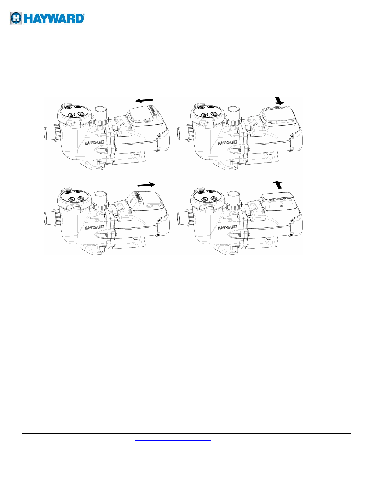
4.11. Digital Control Interface Orientation
The Digital Control Interface can be rotated to any of four desired positions after installation by
removing the two screws securing the interface to the motor drive, lifting the interface and rotating it to
the desired position, and replacing the two screws in the new position. (Figure )
Figure 4.11.-1
4.12. Interface Wall Mounting
The interface can also be wall mounted using the parts supplied in the wall mount kit using the
following procedure.
1. TURN OFF THE ELECTRICAL POWER AT THE CIRCUIT BREAKER.
2. Loosen the two screws securing the user interface to the motor drive. (Figure 4.12-1)
3. Disconnect the short cable that extends out from the motor drive. (Figure 4.12-1)
4. Install the blank cover on the motor drive in the desired orientation. This cover is important to
protect internal electronics. (Figure 4. 13-2)
5. Mount the wall mount plate in the desired location. (Figure 4.12-3)
6. Connect the interface cable as shown in the Wall Mounted Digital Control Interface Wiring Diagram
shown in section 5.2 to the motor drive and user interface PCB. Use the multi-conductor, jacketed
cable suitable for the installation location. The cable must be routed through the “DATA” conduit
opening on the motor drive and through the slot provided on the backside of the wall mount plate,
SP3200DR10. Use a liquid tight cord grip that is appropriately sized for the cable being used to seal
the conduit opening. The cable being used may be up to 500 feet in length.
7. Mount the user interface to the wall mount plate using the two screws. (Figure 4.12-3)
8. Apply power to the system and resume normal operation.
USE ONLY HAYWARD GENUINE REPLACEMENT PARTS
_____________________________________________________________________________________
Hayward Flow Control www.haywardflowcontrol.com 1-888-HAY-INDL (1-888-429-4635)
IS3401VSPFC Rev A 12/08/14
Pg. 11 of 36
 Loading...