

Hayward LifeStar Installation & Operation Manual
1-888-HAY-INDL (1-888-429-4635)
IS3200FC Rev A 5/13/2013
Pg. 1 of 14
www.haywardflowcontrol.com
Hayward Flow Control
HAYWARD FLOW CONTROL
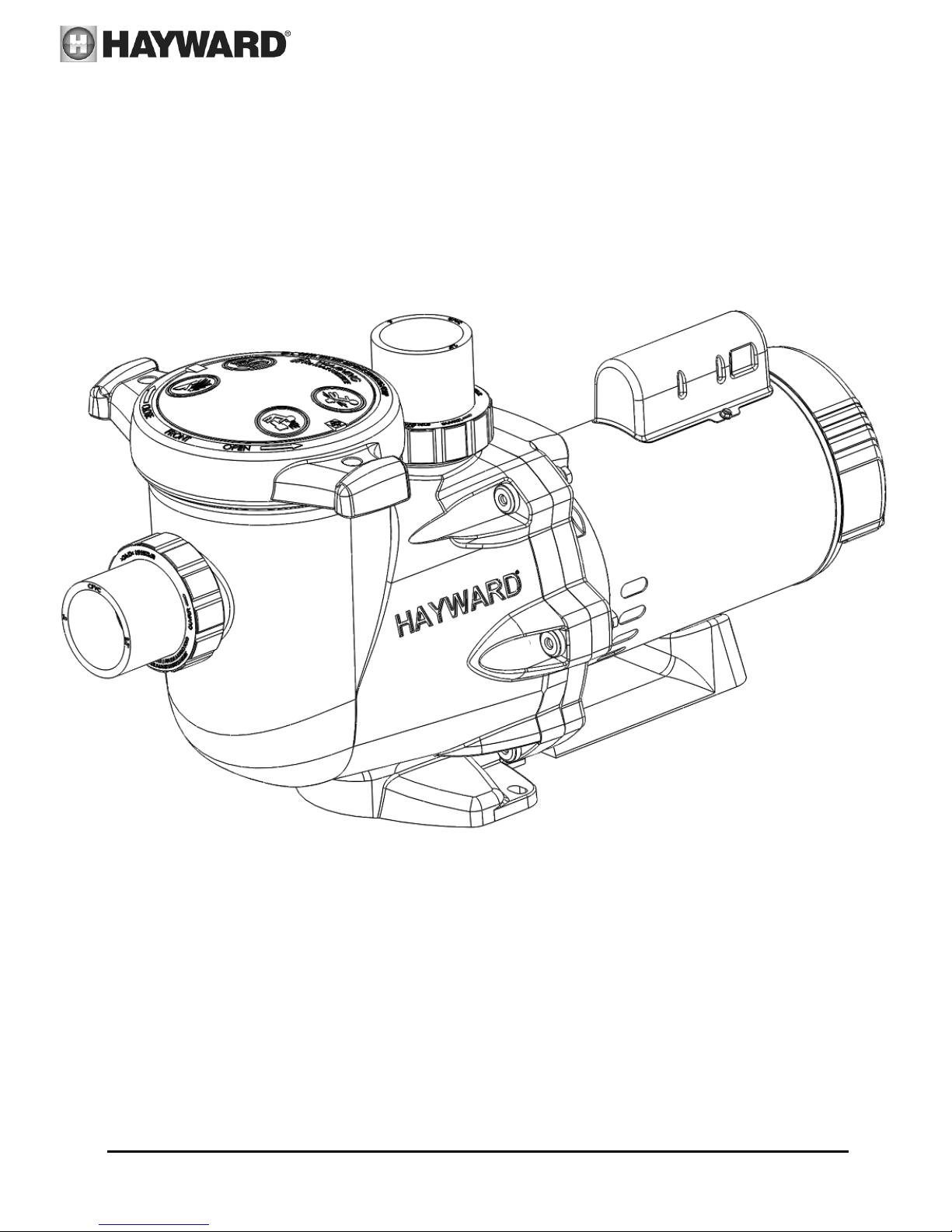
LifeStarTM SERIES AQUATIC PUMP
INSTALLATION, OPERATION AND MAINTENANCE INSTRUCTIONS
TO PREVENT POTENTIAL INJURY, READ THIS MANUAL CAREFULLY AND COMPLETELY.
USE ONLY HAYWARD GENUINE REPLACEMENT PARTS
1-888-HAY-INDL (1-888-429-4635)
IS3200FC Rev A 5/13/2013
Pg. 2 of 14
www.haywardflowcontrol.com
Hayward Flow Control
PLEASE READ THE FOLLOWING INFORMATION PRIOR TO INSTALLING AND USING
HAYWARD LifeStarTM SERIES AQUATIC PUMP. FAILURE TO FOLLOW THESE INSTRUCTIONS
MAY RESULT IN PRODUCT DAMAGE, PROPERTY DAMAGE, PERSONAL INJURY, OR EVEN
DEATH.
1. Hayward Flow Control (Hayward), a division of Hayward Industries, guarantees its products against defective material and
workmanship only. Hayward assumes no responsibility for property damage or personal injury resulting from improper
installation, misapplication, or abuse of any product.
2. Hayward assumes no responsibility for property damage or personal injury resulting from chemical incompatibility between its
products and the process fluids to which they are exposed. Determining whether a particular PVC, CPVC, or PP product is
suitable for an application is the responsibility of the user. Chemical compatibility charts provided in Hayward literature are
based on ambient temperatures of 70°F and are for reference only.
3. Hayward products are designed for use with non-compressible liquids.
4. The maximum recommended fluid velocity through any Hayward product is eight feet per second (8 ft/s). Higher fluid velocity
can result in damage due to the water hammer effect.
5. Piping systems must be designed and supported to prevent excess mechanical loading on Hayward products due to system
misalignment, weight, shock, vibration, and the effects of thermal expansion and contraction.
6. The effect of temperature on plastic piping systems must be considered when the systems are initially designed. The pressure
rating of plastic systems must be reduced with increasing temperature. Maximum operating pressure is dependent upon material
selection as well as operating temperature. Before installing any Hayward product, consult Hayward product literature for
pressure vs. temperature curves to determine any operating pressure or temperature limitations.
7. PVC and CPVC plastic products become brittle below 40°F. Use caution in their installation and operation below this temperature.
8. Due to differential thermal expansion rates between metal and plastic, transmittal of pipe vibration and pipe loading
forces, DIRECT INSTALLATION INTO METAL PIPING SYSTEMS IS NOT RECOMMENDED. Wherever installation
of plastic equipment into metal piping systems is necessary, it is recommended that at least 10 pipe diameters in length of
plastic pipe be installed upstream and downstream of the plastic equipment to compensate for the factors mentioned above.
9. Published operating requirements are based on testing of new pumps using clean water at 70°F. Pump performance is affected
by many factors including fluid chemistry, viscosity, specific gravity, flow rate, and temperature. These should be considered
when sizing Hayward products.
10. Systems should always be depressurized and drained prior to installing or maintaining any Hayward product.
WARNING
Hayward PVC and CPVC products should NEVER be used or tested with compressible fluids such as
compressed air or nitrogen. Use of PVC and CPVC products in compressible fluid applications may result in
product damage, property damage, personal injury, or even death.
WARNING
Hayward PVC and CPVC products should not be used in services with operating temperature below 34°F.
WARNING
Failure to depressurize and drain system prior to installing or maintaining filter vessel may result in product damage,
property damage, personal injury, or even death.
USE ONLY HAYWARD GENUINE REPLACEMENT PARTS
1-888-HAY-INDL (1-888-429-4635)
IS3200FC Rev A 5/13/2013
Pg. 3 of 14
www.haywardflowcontrol.com
Hayward Flow Control
Basic safety precautions should always be followed, including the following: Failure to follow instructions can cause
severe injury and/or death.
This is the safety-alert symbol. When you see this symbol on your equipment or in this manual, look for one of
the following signal words and be alert to the potential for personal injury.
WARNING warns about hazards that could cause serious personal injury, death or major property damage and
if ignored presents a potential hazard.
CAUTION warns about hazards that will or can cause minor or moderate personal injury and/or property
damage and if ignored presents a potential hazard. It can also make consumers aware of actions that are
unpredictable and unsafe.
The NOTICE label indicates special instructions that are important but not related to hazards.
IMPORTANT SAFETY INSTRUCTIONS
WARNING - Read and follow all instructions in this IOM manual and on the equipment. Failure to follow
instructions can cause severe injury and/or death.
WARNING – Suction Entrapment Hazard.
Suction in suction outlets and/or suction outlet covers which are, damaged, broken, cracked, missing, or unsecured can cause severe injury
and/or death due to the following entrapment hazards:
Hair Entrapment- Hair can become entangled in suction outlet cover.
Limb Entrapment- A limb inserted into an opening of a suction outlet sump or suction outlet cover that is damaged, broken, cracked,
missing, or not securely attached can result in a mechanical bind or swelling of the limb.
Body Suction Entrapment- A negative pressure applied to a large portion of the body or limbs can result in an entrapment.
Evisceration/ Disembowelment - A negative pressure applied directly to the intestines through an unprotected suction outlet sump or
suction outlet cover which is, damaged, broken, cracked, missing, or unsecured can result in evisceration/ disembowelment.
Mechanical Entrapment- There is potential for jewelry, swimsuit, hair decorations, finger, toe or knuckle to be caught in an opening of a
suction outlet cover resulting in mechanical entrapment.
WARNING - To Reduce the risk of Entrapment Hazards:
o When outlets are small enough to be blocked by a person, a minimum of two functioning suction outlets per pump must be
installed. Suction outlets in the same plane (i.e. floor or wall), must be installed a minimum of three feet (3’) [1 meter] apart, as
measured from near point to near point.
o Dual suction fittings shall be placed in such locations and distances to avoid “dual blockage” by a user.
o Dual suction fittings shall not be located on seating areas or on the backrest for such seating areas.
o The maximum system flow rate shall not exceed the flow rating of as listed on Table 1.
o Never use system if any suction outlet component is damaged, broken, cracked, missing, or not securely attached.
o Replace damaged, broken, cracked, missing, or not securely attached suction outlet components immediately.
o In addition two or more suction outlets per pump installed in accordance with latest ASME, APSP Standards and CPSC
guidelines, follow all National, State, and Local codes applicable.
o Installation of a vacuum release or vent system, which relieves entrapping suction, is recommended.
WARNING – Failure to remove pressure test plugs and/or plugs used in winterization of the system from the
suction outlets can result in an increase potential for suction entrapment as described above.
WARNING – Failure to keep suction outlet components clear of debris, such as leaves, dirt, hair, paper and
other material can result in an increase potential for suction entrapment as described above.
WARNING – Suction outlet components have a finite life, the cover/grate should be inspected frequently and
replaced at least every ten years or if found to be damaged, broken, cracked, missing, or not securely attached.
CAUTION – Components such as the filtration system, pumps and heater must be positioned so as to prevent
their being used as means of access to the system by unauthorized or unqualified individuals.
WARNING – Never operate or test the circulation system at more than 50 PSI.
WARNING – Never change the filter control valve position while the pump is running.
USE ONLY HAYWARD GENUINE REPLACEMENT PARTS
1-888-HAY-INDL (1-888-429-4635)
IS3200FC Rev A 5/13/2013
Pg. 4 of 14
www.haywardflowcontrol.com
Hayward Flow Control
WARNING – Hazardous Pressure. Circulation systems operate under hazardous pressure during start up, normal operation,
and after pump shut off. Stand clear of circulation system equipment during pump start up. Failure to follow safety and operation
instructions could result in violent separation of the pump housing and cover, and/or filter housing and clamp due to pressure in the system,
which could cause property damage, severe personal injury, or death. Before servicing circulation system, all system and pump controls
must be in off position and filter manual air relief valve must be in open position. Before starting system pump, all system valves must be
set in a position to allow system water to return back to the system. Do not change filter control valve position while system pump is
running. Before starting system pump, fully open filter manual air relief valve. Do not close filter manual air relief valve until a steady
stream of water (not air or air and water) is discharged.
WARNING – Separation Hazard. Failure to follow safety and operation instructions could result in violent separation of
pump and/or filter components. Strainer cover must be properly secured to pump housing with strainer cover lock ring. Before servicing
circulation system, filters manual air relief valve must be in open position. Do not operate circulation system if a system component is not
assembled properly, damaged, or missing. Do not operate circulation system unless filter manual air relief valve body is in locked position
in filter upper body.
WARNING – Risk of Electric Shock. All electrical wiring MUST be in conformance with applicable local codes, regulations,
and the National Electric Code (NEC). Hazardous voltage can shock, burn, and cause death or serious property damage. To reduce the
risk of electric shock, do NOT use an extension cord to connect unit to electric supply. Provide a properly located electrical receptacle.
Before working on any electrical equipment, turn off power supply to the equipment.
WARNING – To reduce the risk of electric shock replace damaged wiring immediately.
WARNING – Ground all electrical equipment before connecting to electrical power supply. Failure to ground all electrical
equipment can cause serious or fatal electrical shock hazard.
WARNING – Do NOT ground to a gas supply line.
WARNING – To avoid dangerous or fatal electrical shock, turn OFF power to all electrical equipment before working on
electrical connections.
WARNING – Failure to bond all electrical equipment to system structure will increase risk for electrocution and could result in
injury or death. To reduce the risk of electric shock, see installation instructions and consult a professional electrician on how to bond all
electrical equipment. Also, contact a licensed electrician for information on local electrical codes for bonding requirements.
WARNING – Risk of Electric Shock. Connect only to a branch circuit protected by a ground-fault circuit-interrupter (GFCI).
Contact a qualified electrician if you cannot verify that the circuit is protected by a GFCI.
WARNING – Risk of Electric Shock . The electrical equipment must be connected only to a supply circuit that is protected by a
ground-fault circuit-interrupter (GFCI). Such a GFCI should be provided by the installer and should be tested on a routine basis. To test
the GFCI, push the test button. The GFCI should interrupt power. Push reset button. Power should be restored. If the GFCI fails to
operate in this manner, the GFCI is defective. If the GFCI interrupts power to the electrical equipment without the test button being
pushed, a ground current is flowing, indicating the possibility of an electrical shock. Do not use this electrical equipment. Disconnect the
electrical equipment and have the problem corrected by a qualified service representative before using.
SAVE THESE INSTRUCTIONS
USE ONLY HAYWARD GENUINE REPLACEMENT PARTS
1-888-HAY-INDL (1-888-429-4635)
IS3200FC Rev A 5/13/2013
Pg. 5 of 14
www.haywardflowcontrol.com
Hayward Flow Control
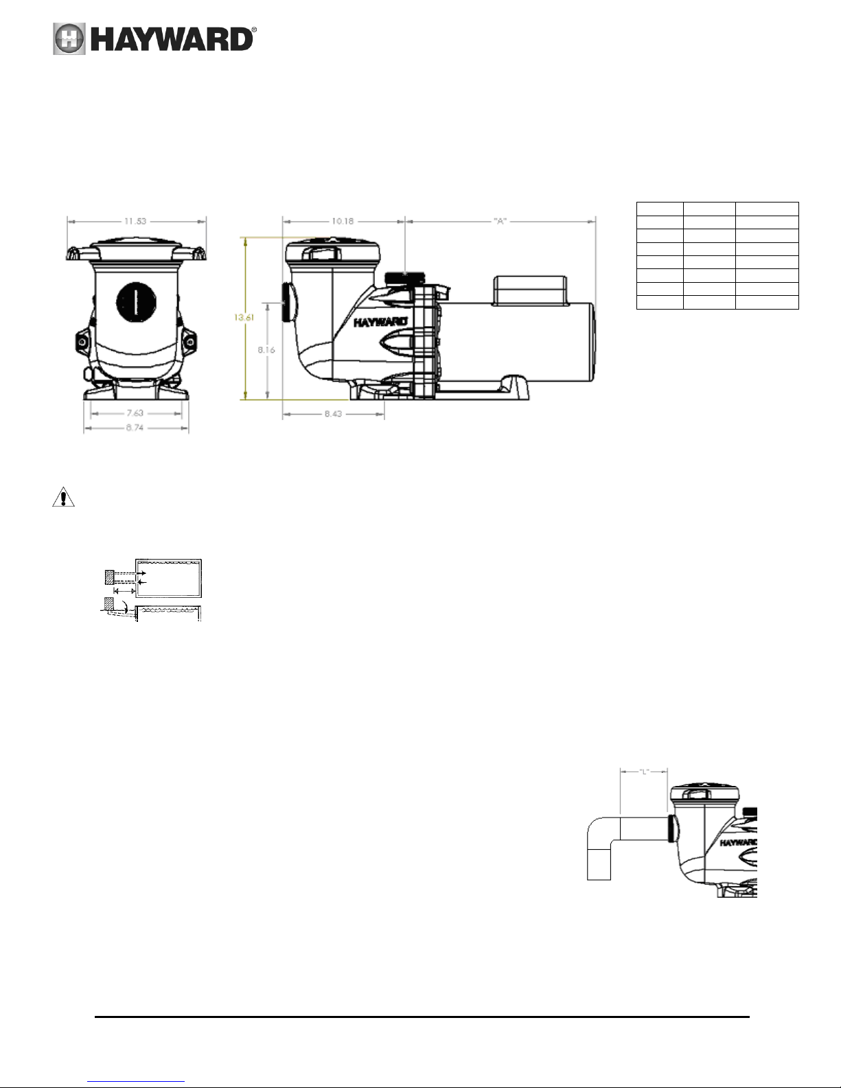
HP
1 ph
3 ph
½
13 5/8”
13 13/16”
¾
13 7/8”
14 3/16”
1
14 3/8”
14 11/16”
1 ½
14 7/8”
15 5/16”
2
14 7/8”
15 5/8”
3
17 1/8”
--
5
17 1/8”
--
General Information
Introduction
This manual contains information for the proper installation and operation of the Hayward LifeStarTM Series Aquatic Pump.
The instructions in this manual MUST be followed precisely. Failure to install according to defined instructions will void
warranty.
Product Specifications
Installation Instructions
WARNING – This product should be installed and serviced only by a qualified professional.
Pump Location
Locate pump as close to system as practical and run suction lines as direct as possible to reduce friction
loss. Suction lines should have continuous slope upward from lowest point in line. Joints must be tight
(but not over-tightened). Suction line diameter must equal or be larger than the discharge line diameter.
Though the pump is designed for outdoor use, it is strongly advised to place pump indoors, or in the
shade to shield them from continuous direct heat. Select a well-drained area that will not flood when it rains. Do NOT
install pump and filter in a damp or non-ventilated location. Keep motor clean. Pump motors require free circulation of
air for cooling.
Pump Mounting
Install pump on a level concrete slab or other rigid base to meet all local and national codes. Secure pump to base with
screws or bolts to further reduce vibration and stress on pipe or hose joints. The base must be level, rigid, and vibration free.
Pump mount must:
Allow pump inlet height to be as close to water level as possible.
Allow use of short, direct suction pipe (to reduce friction losses).
Allow for valves in suction and discharge piping.
Be protected from excess moisture and flooding.
Allow adequate access for servicing pump and piping.
USE ONLY HAYWARD GENUINE REPLACEMENT PARTS
 Loading...