

Page 1
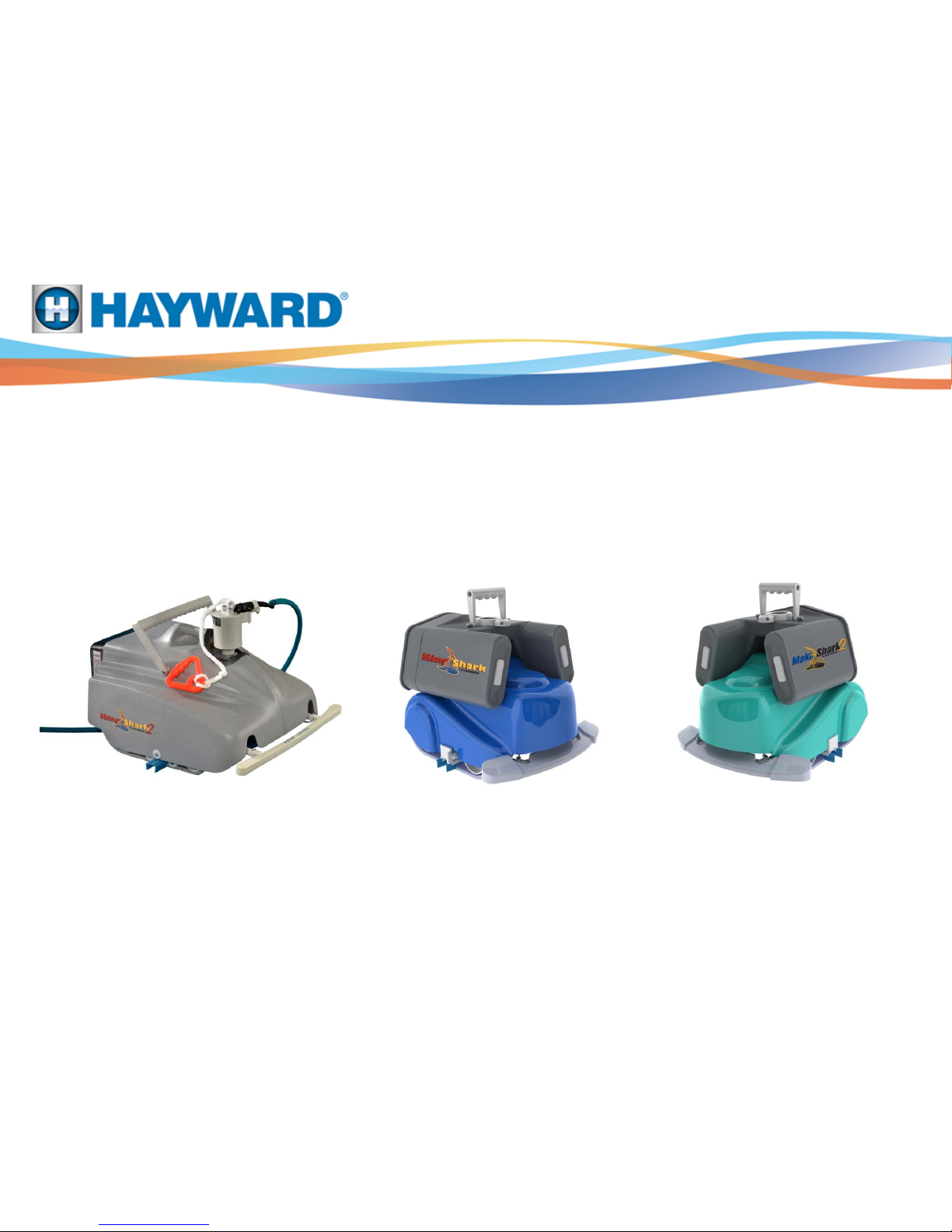
Commercial Cleaner
Troubleshooting Guide
© 2012 Hayward Industries Inc.
Page 2

TABLE OF CONTENTS
Safety Precautions Page 1
Service Tools Page 2
Special Notes Pages 3-4
Removal of Hood Pages 5-6
Filter Removal Pages 7-8
Power Cord Removal Page 9
Swivel Removal Page 10
Accessing the Impeller Page 11
Drive Belt Removal Page 12
Intake Removal Page 13
Drive Wheel Pages 14-17
Motor Removal Page 18
Pump Housing / Gear Box Disassembly Page 19
Solenoid Disassembly Page 20
Bumper / Cable Assembly Removal Page 21
Cable Assembly Components Page 22
Control Panel Components Pages 23-25
Control Panel Troubleshooting Pages 26-28
Control Panel Timer / Relay PCB Testing Pages 29-31
Swivel Voltage Testing Page 32
Motor / Power Cord Voltage Testing Pages 33-35
KingShark 2 / KingShark 2 Plus Tips Page 36
Serial number locator Page 37-38
KingShark 2 and KingShark 2 Plus
Mako Shark 2 and KingShark Troubleshooting
begins on Page 39
Page 3

Disconnecting and removing the unit from the pool immediately after each use will
enhance the cleaner’s life. 150 minutes of operation in a 30’ x 60’ pool should be sufficient
with no more than a few twists in the cord which should be straightened out after each use.
Safety
Page 1
Page 4
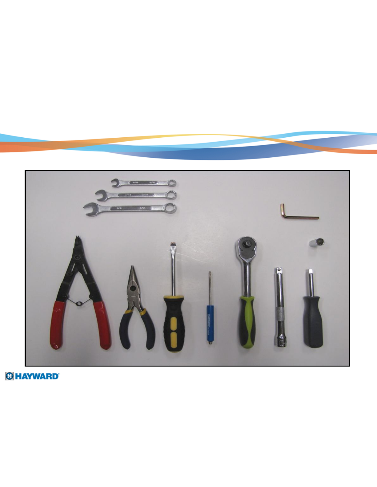
Service Tools
Page 2
3/8“, 5/16“, 7/16“, 1/2"
Wrench
Snap Ring Pliers
Needle Nose Pliers
Flat Tip and Phillips
Screwdriver
Small Flat Tip
Screwdriver
3/8“ Ratchet
3/8“ Socket
Extension
1/4“ Socket
Driver
3/8“, 7/16“, 1/2“
Socket
5/32“, 1/4“ Allen Wrench
Page 5

Special Notes
When disassembling the KingShark 2 and the KingShark 2 Plus,
the ONLY DIFFERENCES between the two cleaners are as follows:
KingShark 2 KingShark 2 Plus
1. Standard 3 prong electrical cord
2. RCX400388 3/4 h.p. w/o swivel.
3. RCX4011 3/4 h.p. w/ swivel.
Page 3
The remote has a maximum communication line to the antenna of 150’.
1. Different pigtail connections.
2. KingShark 2 Plus has a remote.
3. KingShark 2 Plus has a cannon
plug for the control panel.
4. KingShark 2 Plus has solenoids
which control left and right
movement from the remote.
5. RCX4020 3/4 h.p.
Page 6
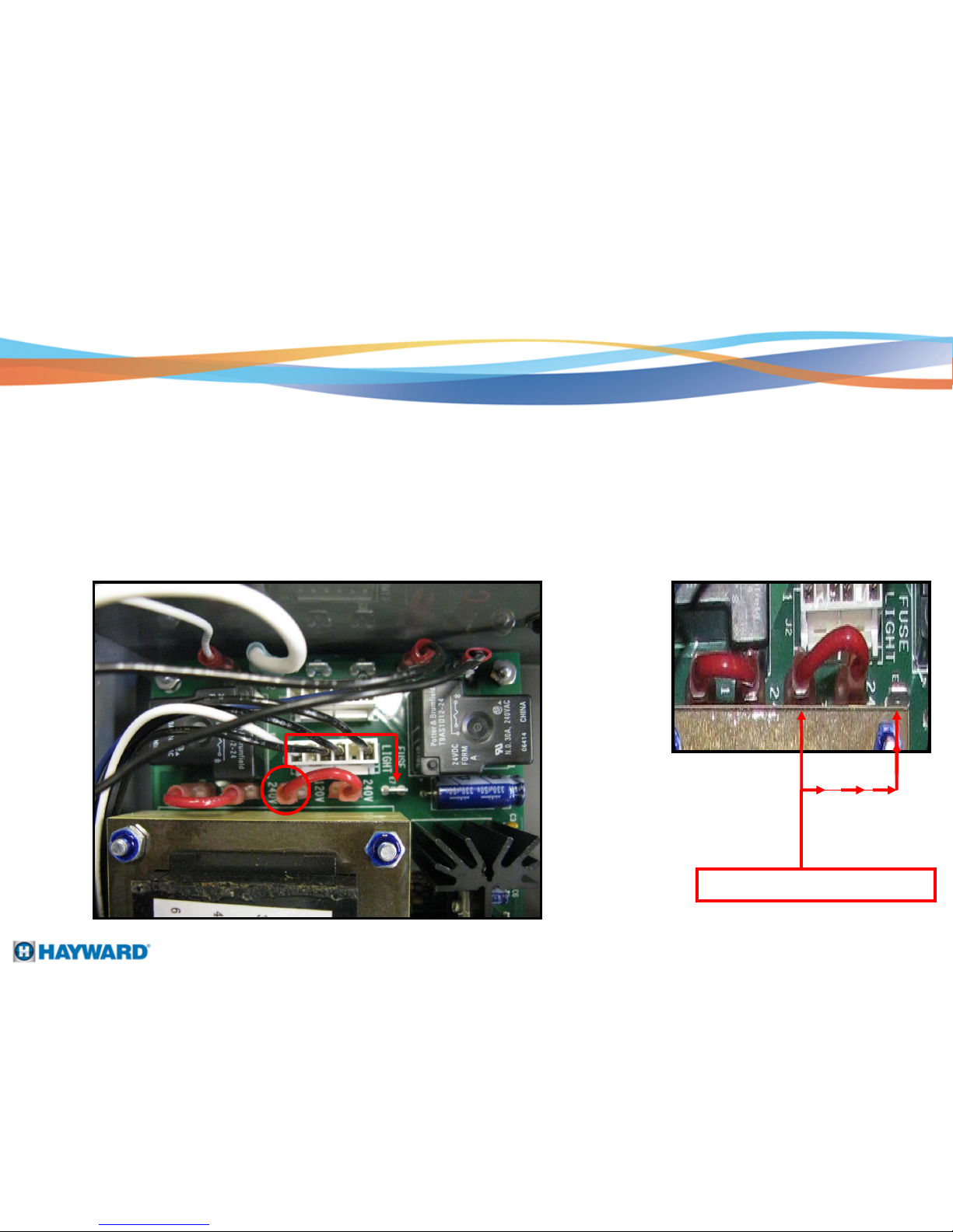
230 VAC Supply to Master Control Panel
ONLY move the E9 connection
E9
When supplying 230 VAC instead of 115 VAC to the Master control panel, the following
jumper cable switch must be moved.
1. Move the jumper wire connection E9 to E7 230 VAC connection on the RELAY
BOARD just above the transformer.
2. Hard wire the power cord to a dedicated 10-15 amp breaker. The master
control panel draws roughly 3 amps.
Page 4
Jumper configured for 240 VAC
Page 7
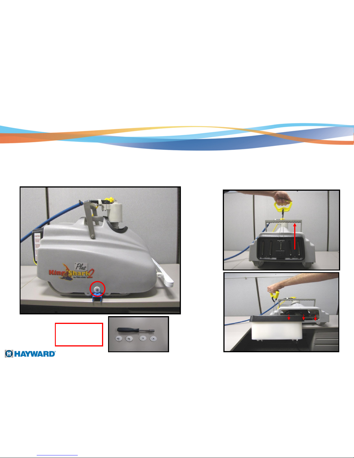
Removal of Hood
Step 1: Step 2:
Remove the two 1/4" – 20 X 3/4" SS bolts from both
sides of the cleaner using a 7/16” socket.
Pull the cartridge handle quick release
UP and then pull the cartridge assembly
back and away from the cleaner.
Note: 1 bolt and 2
plastic washers
per side
Page 5
Page 8
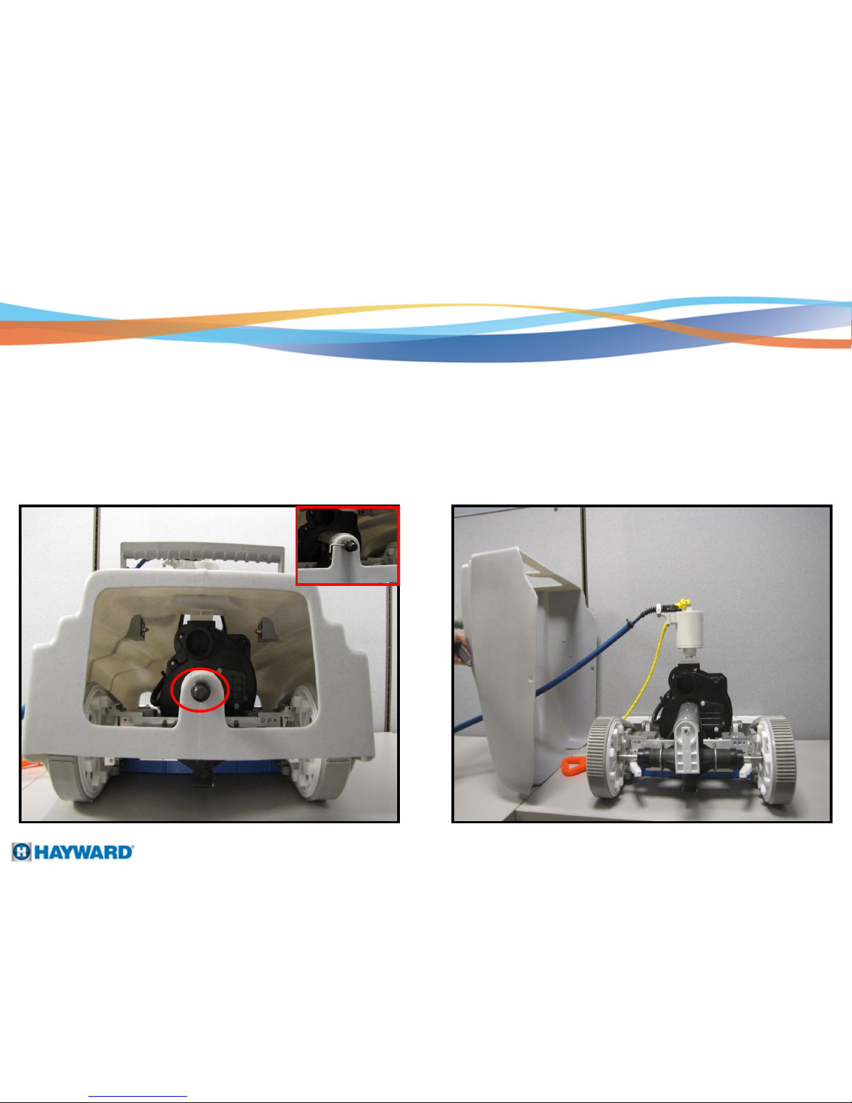
Step 3:
Unscrew the filter retainer knob using a
5/32” Allen Wrench.
Step 4:
Slide the hood cover over the swivel assembly.
Removal of Hood
Page 6
Page 9
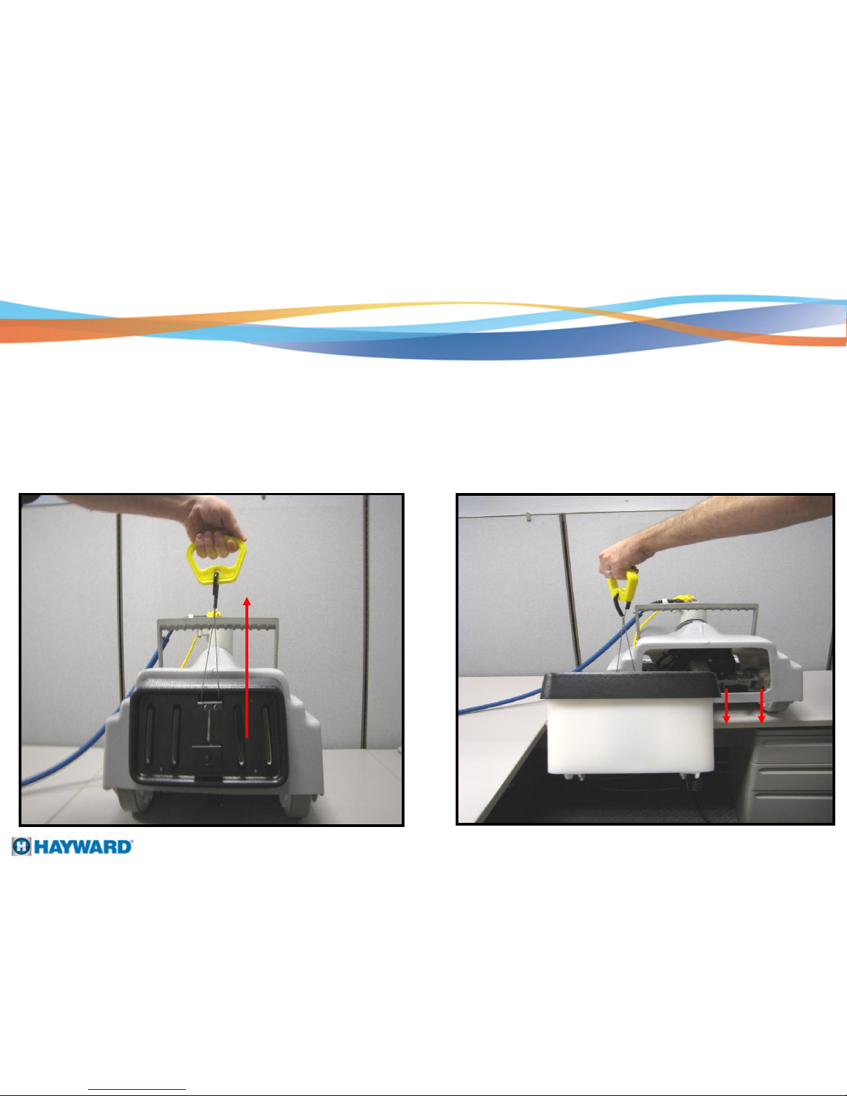
Filter Removal
Step 5:
Pull up on the yellow quick release handle assembly.
Step 6:
Page 7
Pull and slide the filter assembly backwards and
away from the cleaner.
Page 10

Filter Removal
Step 7:
Remove the push style clips
Back Plate
Note : Never remove or adjust the 4 nuts
To clean the filters, spray with
clean water.
Page 8
Lift the housing assembly off the tie rods
/ back plate.
Lift the cartridges up and off the
back plate.
Page 11
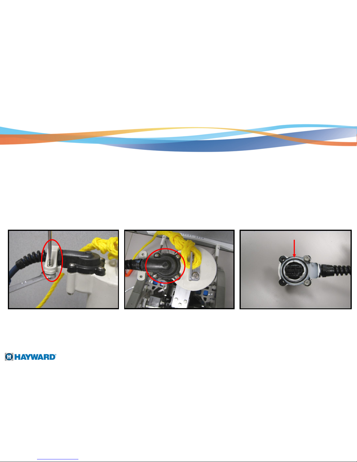
Power Cord Removal
1. Using a flat tip screwdriver and 3/8” wrench, remove the swivel cord clamp.
2. Using a Phillips screwdriver, remove the four screws connecting the power end to the swivel.
3. When reconnecting the power end to the swivel or motor, make sure to use RTV # 162 silicone
rubber sealant and replace the o-ring.
Step 8:
1. 2. 3.
Page 9
o-ring
Page 12
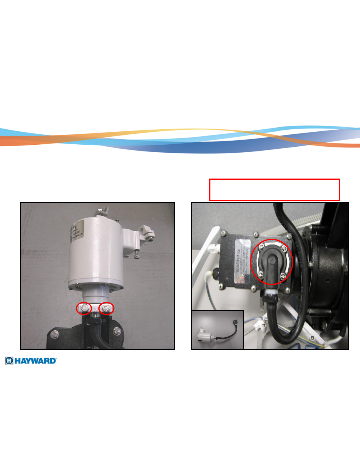
Swivel Removal
Using a 7/16” socket, remove the two 1/4" –
20 X 1-1/4" hex head bolts from the swivel
mounting bracket.
Remove the four screws connecting the power
cord to the motor end.
Note: Make sure to use RTV # 162 Silicone Rubber
Sealant when reconnecting the power cord and replace
the o-ring.
Step 9:
Page 10
Page 13
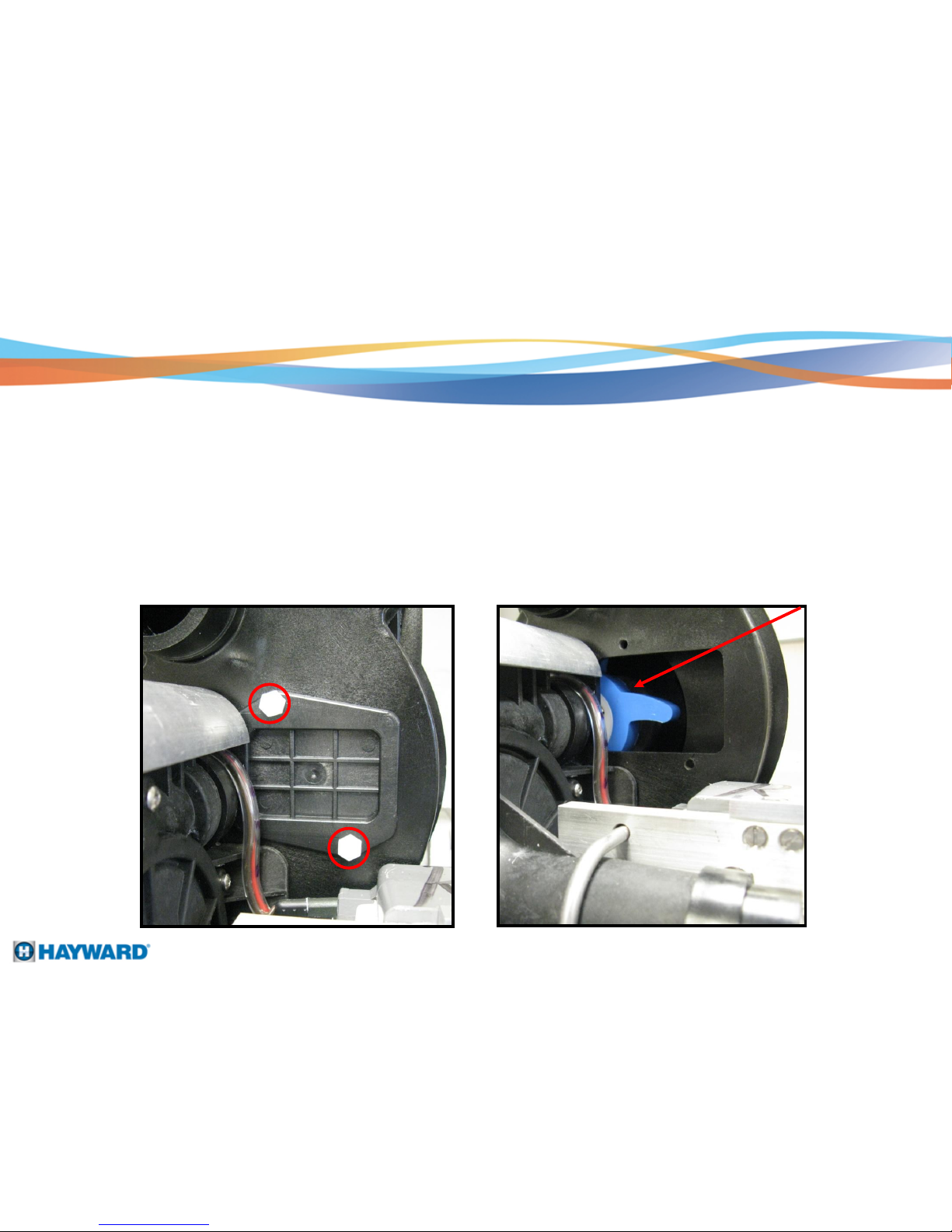
Accessing the Impeller
1. Use a 7/16" socket to remove the two plastic bolts and impeller access plate from the pump housing.
Step 10:
1.
2. After removing the impeller access plate, this will allow you to inspect the impeller and check for
debris or damage inside the impeller area.
2.
Page 11
Page 14
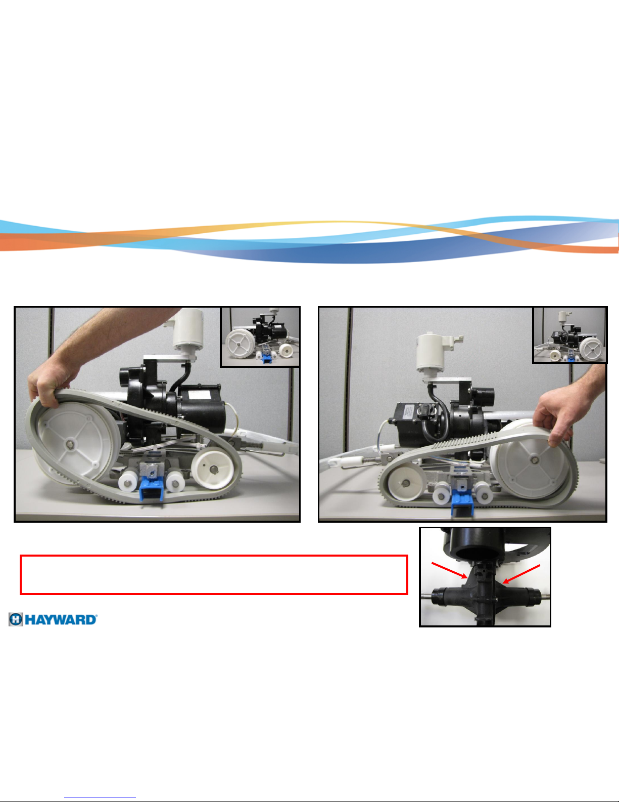
Drive Belt Removal
1. Remove right side drive belt.
Note : When putting the drive belts back on, put the LEFT side on first, then the RIGHT side. This
will prevent possible torque damage where the gear box assembly meets the front housing bell,
since the larger support bracket is on the left side of the gearbox assembly.
2. Remove left side drive belt.
Step 11:
Page 12
Page 15
Intake Removal
Step 12:
1.
NOTE : When removing and reinstalling the Intake, be aware of the 2
plastic washers that seat between the Intake and the base plate.
2.
Page 13
1. Unscrew the 4 screws holding the intake to the base plate, also remove the SS wire baffle.
2. Remove the intake stabilizer from the intake. The stabilizer prevents large debris from entering the cleaner.
Page 16
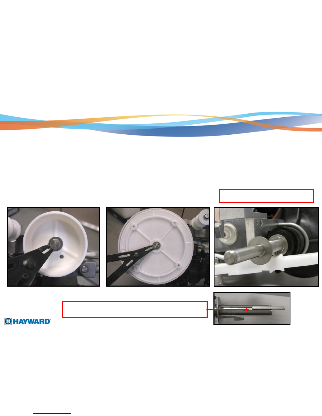
Drive Wheel Disassembly
Step 13:
1. Using the snap ring pliers, remove the snap ring from the front wheels and the rear drive wheels.
2. After removing the snap rings from the wheels, pull the front wheels from the base plate and
remove the drive wheels from the gear box assembly.
Note : There is one SS washer on each
side of the gear arm.
1. Front Wheels 2. Drive Wheels
Page 14
Note: There is one 1/8" SS Key on each rear drive wheel It is
important the key is installed into the wheel prior to inserting the shaft.
Page 17
Drive Wheel Disassembly
1. Use the snap ring pliers to remove the 4 E-Clips from the L & R drive wheels. Remove the 4
plastic washers / spacers.
2. Remove the 2 indicator screws from the drive wheels – Each set of screws indicate LEFT
drive wheel specific or RIGHT drive wheel specific. Below the 2 indicator screws, the letter
L or R will be molded into the wheel.
1.
2.
Step 14:
Page 15
Page 18

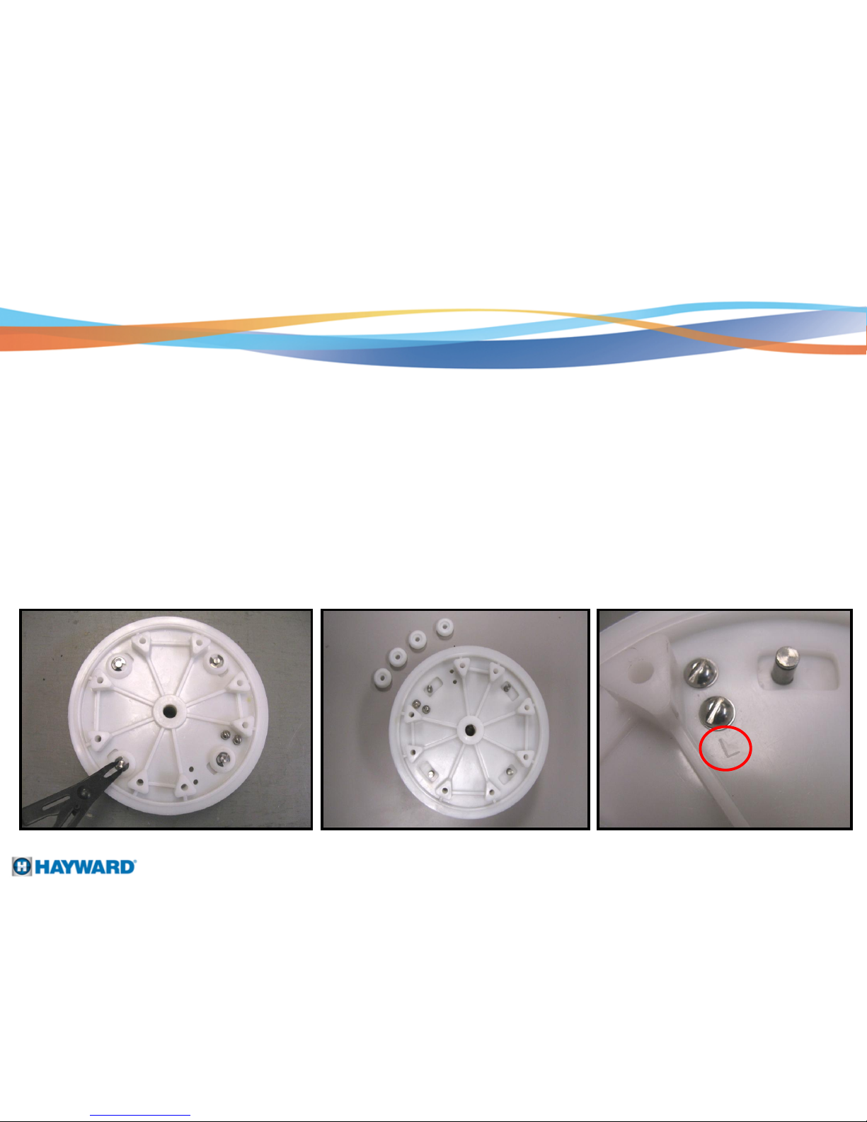
Drive Wheel Disassembly
2. Remove the Gear Ring
3. Remove the Sun Gear
1. Remove the 4 Button Washers
Step 15:
4. Remove the 4 Planetary Gears 5. Remove the Wheel Lock
Page 16
Page 19

Drive Wheel Reassembly
1. When reinstalling the drive wheels, make sure the Wheel Locks are installed in the correct direction and
position. The photo’s below indicate the correct position and direction.
LEFT DRIVE WHEEL RIGHT DRIVE WHEEL
2. The outside wheel plate screws must match the L or R indicator markings on the outside wheel plates.
2.
L
Page 17
1.
R
Page 20

Motor Separation
Step 16:
1. Use a 1/4" allen wrench to remove the 2 bolts and washers. Once these are removed, lift the motor from
the base plate.
2. Use a 1/2" socket to remove the 5 bolts and washers that hold the motor to the pump housing.
1. 2.
3. Use a flat tip screw driver to remove the 4 impeller screws.
4. Unscrew the 2 screws and 1 - 7/16” bolt to separate the motor from the housing bell.
3.
Page 18
4.
Left View Right View
Page 21

Pump Housing / Gear Box Disassembly
Gear Box Assembly
Pump Housing
1. Use a 7/16" socket to remove the 3 bolts from the pump housing. Pull the pump housing from the
gear box assembly.
2. After removing the 3 - 7/16" bolts, note the length and location of each bolt for reinstallation.
1. 2.
Step 17:
Page 19
Page 22

Solenoid Disassembly
1. Use a 7/16" wrench to remove the 4 retention nuts from the U bolts.
2. Once the 4 retention nuts are removed, the solenoids can be set aside. To separate the solenoids
from the motor, pull and separate at the quick connection at the solenoid.
Note: Solenoids are marked left (L) and right (R) . The power cord that has the black lines
indicates the right solenoid connection. (see insert picture, photo #2)
Step 18:
Page 20
1. 2.
Page 23

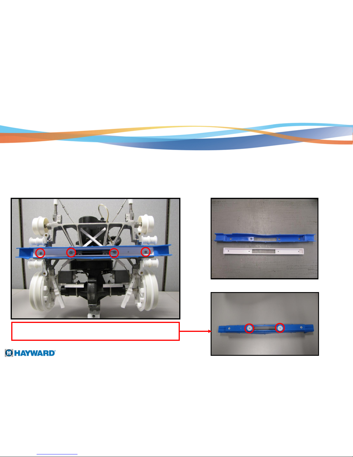
Bumper / Cable Assembly Removal
1. Remove the two 3/8” nuts (top), four flathead screws (center), and two pins (bottom).
2. Slide the bumper from the arm sensor bar.
1.
Step 19:
Page 21
Note: Both the reversing arms and cable assembly can be
turned over and be reused
2.
Page 24

Note the proper location of the washers
and spacer when reinstalling the L & R
reversing arms.
L side top view R side top view
underneath view
Back to front view - TOP
(TOP)
(BOTTOM)
2 plastic spacers
1 plastic spacer
Cable Assembly
1. Tension cables / cable assembly are adjustable.
Once the cable assembly is reinstalled, push in
should touch the inside of the drive wheels.
Cable assembly’s do not come pre-tensioned from the manufacturer
Instructions for Reinstalling the Cable Assembly
Page 22
Release the sensor bar, it should “spring“ back to it’s
on the sensor bar. The L & R reversing arms
normal position, if it doesn’t, tighten or loosen accordingly
(blue).
3.
2.
Page 25

Master Control Panel
Relay Board
Transformer
Receiver Board
24 VDC relays
24 VDC relays
Power out to cleaner
Relay Board / Receiver Board
Antenna
Page 23
Incoming power supply
AC to DC rectifier
Page 26

Master Control Panel
Fuse
Power Indicator Light Auto Turn On / Off
Switch
Power On / Off
Switch
Note: Ribbon cable
disconnects at the Timer
Board
Timer Board
Page 24
(Back Side of Front Panel)
Display ribbon cable
Page 27

Master Control Panel
Power cord MUST be plugged
outlet equipped with a
( GFCI )
1.
1.
into a grounded electrical
Ground Fault Circuit Interrupter
If you supply power to the master control panel and you
have no display, this is NORMAL.
Unless you have the Cannon Plug power cord from the
swivel connected to the 2 center ports, the display will be
blank. This will prevent any shocking hazards that may
occur with the power connection at the master control panel.
Step 20:
Page 25
Page 28

Master Control Panel
Step 21:
Page 26
Correct power to Master Control Panel but NO display
1. 2.
Put meter lead on the on/off switch and one lead to ground, 115 VAC should be present.
1.
2.
NOTE: Check voltage on LEFT
connection of switch
Make sure power is ON. Put one meter lead on L1 connection and one lead on L2, 115 VAC should
be present.
Page 29

Master Control Panel
Correct power to Master Control Panel and NO display
Check for a blown fuse. Twist the fuse left and pull out for access.
Page 27
Slo-Blo 1 amp / 250VP
Do a continuity check on the fuse to verify if fuse is good or bad
Page 30

BRN YEL BL
R R
BLACK
GR
WH
24 VDC
115 VAC
Master Control Panel Cannon Plug
Step 22:
Page 28
To verify 115 VAC is being supplied through the female cannon plug receiver, install
a jumper wire into the 2 center ports. Power the unit on and press the“Start“ button
until “RUN“ is on the display. Then, stick one meter lead into the black port and the
other lead into the white or green port. 115 VAC + or - should be present.
Page 31

Master Control Panel
Timer PCB Testing
On RELAY PCB at REMOTE J4
Step 23:
If the unit still does not run, proceed to Step 25 on Page 32.
Page 29
- Using RED lead of DC voltmeter at green wire on J4 and BLACK lead of DC voltmeter at
COM (E12). Voltmeter should read 24 VDC. Now, push RIGHT TURN button on the remote,
voltmeter should read 0 VDC
- Do the same test procedure on the RED wire – push LEFT TURN button on the remote,
voltmeter should read 0 VDC
Page 32

Master Control Panel
RELAY PCB Testing
On RELAY PCB at J3 (B A G H F)
Yellow wire is the common wire to both solenoids
Blue wire is the LEFT Turn solenoid
Brown wire is the RIGHT Turn solenoid
- Using DC Voltmeter, check voltage between the yellow wire and the blue wire. 24 VDC should be
present while pushing the LEFT TURN button on the remote
- Using DC Voltmeter, check voltage between the yellow wire and the brown wire. 24 VDC should be present
while pushing the RIGHT TURN button on the remote.
- Using DC Voltmeter, check voltage between either the brown or blue wire to yellow. 24 VDC should be
present while pushing the REVERSE TURN button on the remote.
or
Step 24:
Page 30
Note: Voltage can vary
between 22-28 VDC
Page 33

Master Control Panel
1.
2.
Step 25:
Page 31
1. After testing the RELAY PCB Board (Step 24), if the tests do not match the correct voltages, then
the RELAY PCB Board will need to be replaced.
2. If the problem still exists after replacing the RELAY PCB Board, remove the cannon plug from the
master control panel. Insert the jumper wire into the 2 center ports of the connector plug at the
master control panel. Repeat steps 24 & 25. If steps 24 & 25 pass the testing, the motor and cord
need to be test separately to determine which one needs to be replaced.
Page 34

Voltage Check to Swivel
To verify voltage is passing through the power supply cord to the swivel :
1. Power the system off
2. Disconnect the power end connection at the swivel
3.Power the system ON and make sure the RUN light is illuminated.
4. Put meter leads on the black and white ports. 115 VAC should be present. If not, verify
breaker is good, ON switch is ON, and all power is correct.
POWER END CONNECTION
WH
BLACK
power cord
Step 26:
Page 32
.
Page 35

Voltage Check to Motor
Step 27:
Old motor New motor
Power end connection
WH
BLACK
To verify voltage is getting through the swivel to the MOTOR :
1. Power the system off
2. Disconnect the power end connection at the motor
3. Power the system on and make sure the RUN light is on the display
4. Put meter leads on the white and black ports, you should get 115 VAC
Page 33
cord
Page 36

Ohm Check at Motor
Step 28:
Ohm meter
-0.9 ohms-1.3 ohms
for 115 VAC
-4.3 ohms-6.3 ohms
for 240 VAC
Page 34
Page 37

Cord Inspection
SWIVEL CONNECTOR END
cord
direction
WH BR BLACK
BLUE
GR
YELLOW
Step 29:
Page 35
1. Make sure the cannon plug is connected. Power the unit on. Press the start button
until Run is displayed.
1.
2. Put one meter lead into the white port, and one meter lead into the black port at the swivel
connector end where it connects to the swivel. 115 VAC should be present.
2.
Undo the power connection at the swivel. Remember to replace the o-ring and to use RTV #162
silicone rubber sealant when reconnecting the swivel connector end.
Page 38

Page 36
Sensor Bar adjustments and other minor repairs (Make all adjustments in ¼" increments)
A. Raise Sensor Bar if machine:
1. Fails to climb out of deep end.
2. Turns or hesitates on pool drain.
3. Turns away from curved wall too soon.
B. Lower Sensor Bar if:
1. Tips over before tripping or sensing wall.
2. Turns or hesitates on pool drain.
C. Sensor Bar adjustments required if machine turns in circles or twists cord:
1. Sensor bar not level or too high, possibly hitting the hood.
2. Thread on reversing arm is worn or stripped, not allowing reversing mechanism to disengage.
3. Sensor Bar Cable screws are loose.
4. Sensor Bar Cable is broken.
5. Drive Wheel is broken.
Check Sensor Bar regularly and keep the sensor bar level at all times !
Loss of vacuuming action
1. Filter may be clogged, slowing the flow of water through the unit. Clean the filters.
2. Suction area may be obstructed by large debris. Unplug power cord and remove obstruction.
No apparent power
1. Electrical outlet may be dead. Check electrical GFCI outlet. Check Fuses and breakers. Verify power switch is on.
2. Object lodged in the impeller.
3. Unit runs for a short distance and stops. Check for over load of the electrical circuit or faulty motor. DO NOT USE EXTENSION CORDS
4. Motor runs but machine becomes or is motionless. Gear box could be worn or drive pin could be sheared.
Machine tips over
1. Filters are dirty.
2. Sensor Bar set too high.
3. Tipping in certain situation can be prevented by purchasing a float and installing per instructions.
Disconnecting and removing the unit from the pool immediately after each use will enhance the life of the cleaner. 4 hours operation in a
50’ x 100’ pool should be sufficient with not more than a few twists in the cord which should be straightened out after each use.
KingShark 2 / KingShark 2 Plus Tips
Page 39

Serial Number Locations – March 2010 & prior
Page 37
(bottom side of Gear Box Assembly)
Serial numbers for the Commercial Units can be found in the three locations indicated below
First two numbers of a serial number:
10 = MAKOSHARK
30 = MAKOSHARK2
50 = KINGSHARK
70 = KINGSHARK2
90 = KINGSHARK2 PLUS
LETTER:
A=January
B=February
C=March
D=April
E=May
F=June
G=July
H=August
J=September
K=October
L=November
M=December
* Fourth Position indicates year of manufacture
For example, 9 = 2009
Page 40

Currently we are using the 17 digit serial number sequence
used on Hayward products. This will be located on the
gear box assembly and on the motor.
Example:
Model # Serial #
RC9860DCC 21121102005246000
2112 - location made
11 - year made
02 - month made
Page 38
Serial Number Locations after March 2010
Page 41

Mako 2 & King Shark Troubleshooting
TABLE OF CONTENTS
Filter Removal Page 40
Handle Removal Page 41
Filter Housing Removal Page 42
Hood Removal Page 43
Cord Assembly Removal Page 44
Drive Belt Removal Page 45
Gearbox Assembly Removal Page 46
Impeller and Motor Removal Pages 47-48
Pump Housing and Base Disassembly Pages 49-52
Troubleshooting Pages 53-54
Page 39
Page 42

Filter Removal
Remove both clips from the rear
of the unit.
.
Note: Elements can be cleaned by gently spraying
with a garden hose. Be careful not to use high
pressure as this may cause damage to the elements.
Step 3: Remove filter elements.
Step 1: Step 2: Remove the back cover from the
filter housing.
Page 40
Page 43

Handle Removal
Step 1: Use a flat head screwdriver on both ends of the handle pin to unscrew and remove.
Page 41
Page 44

Slide Ring Adapter off the housing and remove the two screws to remove the ring
adapter from cord.
Lift the filter housing from the cleaner.
Filter Housing Removal
Step 1:
Step 2:
Page 42
Page 45

Hood Removal
Remove the bolt from the handle
riser using 7/16” socket.
Remove the handle riser.
Remove the hat riser. Lift the body off.
Step 1: Step 2:
Step 3: Step 4:
Page 43
Page 46

Cord Assembly Removal
Remove the bolt from the pump
housing using a 7/16" socket.
Remove the 4 screws
from the motor.
Pull the plug away from the motor.
Note: When replacing the cord assembly
clean surface thoroughly and use
new o-ring and RTV #162 White
Silicone for a water tight seal.
Step 1:
Step 2:
Step 3:
Page 44
Page 47

Drive Belt Removal
Looking at the cleaner from the rear, remove the RIGHT drive belt from
the rear wheel, and then the front wheel.
Step 2: Remove the LEFT belt.
Note: Look at the
cleaner from the rear
and note that the gear
box has a Support on
the left side of the unit.
Left Right
Note: When installing the drive
belts install the left belt first and
then the right belt. This will remove
stress from the right side of
the gearbox which does not have
the additional support.
Step 1:
Page 45
1. 2.
3.
4.
Page 48

Step 1: Remove the five bolts from the rear of the gear box assembly using a 7/16" socket.
Gear Box Assembly Removal
1
2
3
4
5
Step 2: Pull the gear box away from the pump housing.
Gear Box
Page 46
Page 49

Impeller and Motor Removal
Pull the impeller from the
impeller drive collar.
Pull the impeller drive collar
from the motor shaft.
Step 1:
Step 2:
Page 47
Page 50

Impeller and Motor Removal
Step 3: Remove the 3 motor screws.
Step 4: Slide the motor away from the pump housing.
1. 2. 3.
Page 48
Page 51

Pump Housing and Base Disassembly
Step 1: Remove the 2 blue intake blades by pulling them from the slide.
Step 2: Remove the two bolts from the bottom of the unit using a 1/2" socket.
Step 3: Remove the pump housing from the base.
Page 49
Page 52

Pump Housing and Base Disassembly
Step 4: Remove the snap ring from the front wheel.
Step 5: Slide the wheel off of the axle.
Step 6: Repeat the 2 previous steps on the opposite side of the base.
Note: Sensor Bar and Reversing Arms are both reversible. As they become worn, they can
be turned over to use the other side. This will extend the life of the part.
Page 50
Page 53

Pump Housing and Base Disassembly
Remove the 2 flat head screws from the sensor bar. This will allow removal of
the sensor bar from the base.
Pull the 2 cotter pins at the opposite end of the cables.
Step 7:
Step 8:
Page 51
Page 54

Step 9: Remove the two bolts from the reversing arms using a 5/16” socket.
Note: There are washers
located on either side of the
reversing arm to allow
smooth movement.
Pump Housing and Base Disassembly
Washer locations
Page 52
Note: The steps to disassemble & reassemble the drive wheels are identical to those of
the KingShark II and KingShark II Plus. Detailed steps can be found on pages 14 – 17.
Page 55

Troubleshooting
Sensor Bar adjustments and other minor repairs (make all adjustments in ¼” increments).
A. Raise Sensor Bar if machine:
1. Fails to climb out of the deep end.
2. Turns or hesitates on pool drain.
3. Turns away from curved wall too soon.
B. Lower Sensor Bar if:
1. Tips over before tripping or sensing wall.
2. Turns or hesitates on pool drain.
C. Sensor Bar adjustments required if machine turns in circles or twists cord.
1. Sensor Bar not level or too high possible hitting hood.
OR
2. Thread on reversing arm #RC1703 is worn or stripped not allowing
reversing mechanism to disengage.
3. Sensor Bar cable screws are loose.
4. Sensor Bar cable is broken.
5. Drive wheel is broken.
D. Remember this basic rule:
Check Sensor Bar regularly and keep the Sensor Bar level at ALL times.
Page 53
Page 56

Troubleshooting
Loss of vacuuming action:
A. Filter may be clogged, slowing the flow of water through the unit. Clean the filters.
B. Suction area may be obstructed by large object.
No apparent power:
A. If the machine does not move:
1. Verify power at the electrical outlet.
2. Object lodged in impeller.
3. A short in the motor, check the ground fault interrupter.
4. Unit runs for a short distance and stops. Check for overload of the
electrical circuit or faulty motor. (DO NOT use extension cords.)
5. Motor runs but machine becomes or is motionless. Gear box could be
worn or drive pin could be sheared.
Machine tips over:
A. Filter loaded with sand or debris.
B. Sensor Bar is set too high.
Page 54
 Loading...