

Page 1
HAYWARD MICROPROCESSOR CONTROL/TIMER
OWNER’S MANUAL & INSTRUCTION SHEET
This high performance timer is adaptable to all 115 volt Flex-48 style aboveground pool pump motors.
Please follow all instructions closely.
(
m
WARNING: Electric Hazard. Failure to follow
instructions can result in serious injury or death.
Disconnect power supply before servicing.
All electrical connections must be performed by qualified
personnel in compliance with applicable electrical codes.
A ground fault circuit interrupter (GFCI) must be installed as
required by electrical codes.
Keep fingers and foreign objects away from openings and moving
parts.
Motor must be suitably grounded. Connect ground wire to green
Use motor bonding lug to connect the motor with other bonded
parts using a #8 AWG conductor (#6 AWG in CANADA) as required
by electrical codes.
Replace all covers before operation.
Power source must agree with nameplate.
•
•
•
•
•
•
•
•
WARNING—To reduce risk of injury, do not permit children to use this
product unless they are closely supervised at all times.
CAUTION—This pump is for use with permanently installed pools and
may also be used with hot tubs and spas if so marked. Do not use with
storable pools. A permanently installed pool is constructed in or on
the ground or in building such that it cannot be readily disassembled
for storage. A storable pool is constructed so that it is capable of
being readily disassembled for storage and reassembled to its original
integrity.
If installed within an outer enclosure or beneath the skirt of a hot tub
or spa, adequate ventilation and free circulation of air must be
provided to prevent overheating of the motor.
Use motor bonding lug to connect the motor with other bonding parts
using a #8 AWG conductor as required by electrical codes. NOTE:
The national Electrical Code (NEC) permits use of a cord with a
maximum 3 ft. (1m) length. If your pump is equipped with a cord
complying with the NEC, items 5 through 8 apply.
WARNING—To reduce risk of electric shock, replace damaged cord
immediately.
WARNING—To reduce risk of electric shock, do not use extension
cord to connect unit to electric supply; provide a properly located
outlet. Qualified personnel must do all electrical wiring. All electrical
wiring must be in conformance with applicable local codes and
regulations.
CAUTION—The NSPI–4 Standard (Above-Ground and On-Ground
Pools) advises that components such as the filtration system, pumps
and heater be positioned so as to prevent their beingused as a means
of access to the pool by young children.
CAUTION—All suction and discharge valves must be open when
starting the system. Failure to do so could result in severe personal
injury and/or property damage.
IMPORTANT SAFETY INSTRUCTIONS
When installing and using this electrical equipment, basic safety precautions should always be followed,
including the following: Failure to follow instructions may result in injury
READ AND FOLLOW ALL INSTRUCTIONS
CAUTION: We highly recommend having a qualified professional install the product. All suction and discharge valves must be
open when starting the system. Failure to do so could result in severe personal injury.
SAVE THESE INSTRUCTIONS
1.
2.
3.
4.
5.
6.
7.
8.
9.
10.
11.
WARNING—Risk of Electric Shock. Connect
only to a grounding type receptacle protected
by a Ground Fault Circuit Interrupter (GFCI).
Contact a qualified electrician if you cannot
verify that the receptacle is protected by GFCI.
Do not bury cord. Locate cord to minimize
abuse from lawn mowers, hedge trimmers, and
other equipment.
DANGER—SUCTION ENTRAPMENT HAZARD.
Can cause serious injury or death. Do not use
this pump for pools or spas containing suction
drains unless pump is connected to at least two
(2) functioning suction outlets at least three (3)
feet apart. Installation of pump and suction
outlets must be in compliance with all
applicable local building codes.
grounding screw and for cord connected units use properly
grounded GFCI protected outlet.
WARNING
IS1500ST-04
Rev . A
Page 2

TO SET TIMER:
1. Move switch from “OFF” to “PROGRAM” to “OFF” to achieve each setting.
1. Note: while switch is in “program position” a tone will be heard.
2. Move switch from “OFF” to “RUN”.
3. Repeat step 1 to achieve desired setting.
SINGLE SPEED MOTOR SETTINGS:
Setting 1—Pump runs 24 hours continuously–(tone heard once)
Setting 2—Pump runs 18 hours and is off for 6 hours–(tone heard twice)
Setting 3—Pump runs 12 hours and is off for 12 hours–(tone heard three times)
Setting 4—Pump runs 6 hours and is off for 18–(tone heard four times)
NOTE: When the timer is switched from “OFF” to “PROGRAM” an audible tone
sound is heard. This allows the pump to differentiate between settings.
DUAL SPEED MOTOR SETTINGS:
Setting 1—Pump runs 24 hours on Hi Speed–(tone heard once)
Setting 2—Pump runs 18 hours on Hi Speed and 6 hours on Low Speed–(tone heard twice)
Setting 3—Pump runs 12 hours on Hi Speed and 12 hours on Low Speed –(tone heard three times)
Setting 4—Pump runs 6 hours on Hi Speed and 18 hours on Low Speed–(tone heard four times)
TO OVERRIDE TIMER SETTING:
Move switch from “RUN” to “OFF” back to “RUN” within 3 seconds. The pump will run for 1 hour and then return
to the programmed mode you’ve selected.
If a power failure occurs: Once power is restored, the timer will automatically default to the
programmed mode, adding the length of time of the power failure.
FOR REPLACEMENT TIMER ORDER PART NUMBER—SP1500FT
INSTALLATION INSTRUCTIONS FOR EXISTING PUMPS:
HAYWARD MICROPROCESSOR CONTROL/TIMER
1. Only qualified personnel should field wire motor. All wiring must be done in accordance with applicable electrical codes.
Make certain that electrical power to pump has been disconnected before attempting to install pump timer SP1500FT.
2. Remove existing plastic motor canopy from motor by loosening canopy retaining screw in center of canopy. If motor is
equipped with a rocker or toggle switch remove the switch jumper wires from the motor terminal board. For single speed
motors: If one of the rocker or toggle switch jumper lead terminals is not accessible, disconnect the accessible terminal
and connect it to the motor terminal board position (5) formerly used by the other (discarded) jumper wire.
3. Use the red, (not provided with all SP1500FT units) black and white jumper wires provided to make the required
connections between the timer printed circuit board located in the new motor canopy and the motor terminal board. If your
pump is a single speed model you will not need the red jumper wire. The connection points for the jumper wires are
shown on the schematic wiring diagrams below. Make certain you refer to the correct diagram for your pump as both the
single speed and two speed diagrams are shown.
4. The black and white supply voltage wires (either cordset or conduit) must be connected to printed circuit board
terminals (P1) and (P2) respectively. In order to accomplish these field connections the black and white supply voltage
leads must have .250 inch push-on electrical terminals.
5. Make certain that the field supply green grounding lead is secured to the green #10 grounding screw positioned in the
motor end frame. Install the new timer canopy by locating and tightening the canopy retaining screw. Exercise care not to
pinch the jumper or cordset leads while installing the timer canopy onto the motor.
6. Reconnect electrical power to pump and follow operating instructions to program timer.
OPERATIONAL INSTRUCTIONS:
Your integrated timer module has been designed with four (4) possible timer settings plus a manual override
control.
***Run duration is set at the time of programming.
Page 3
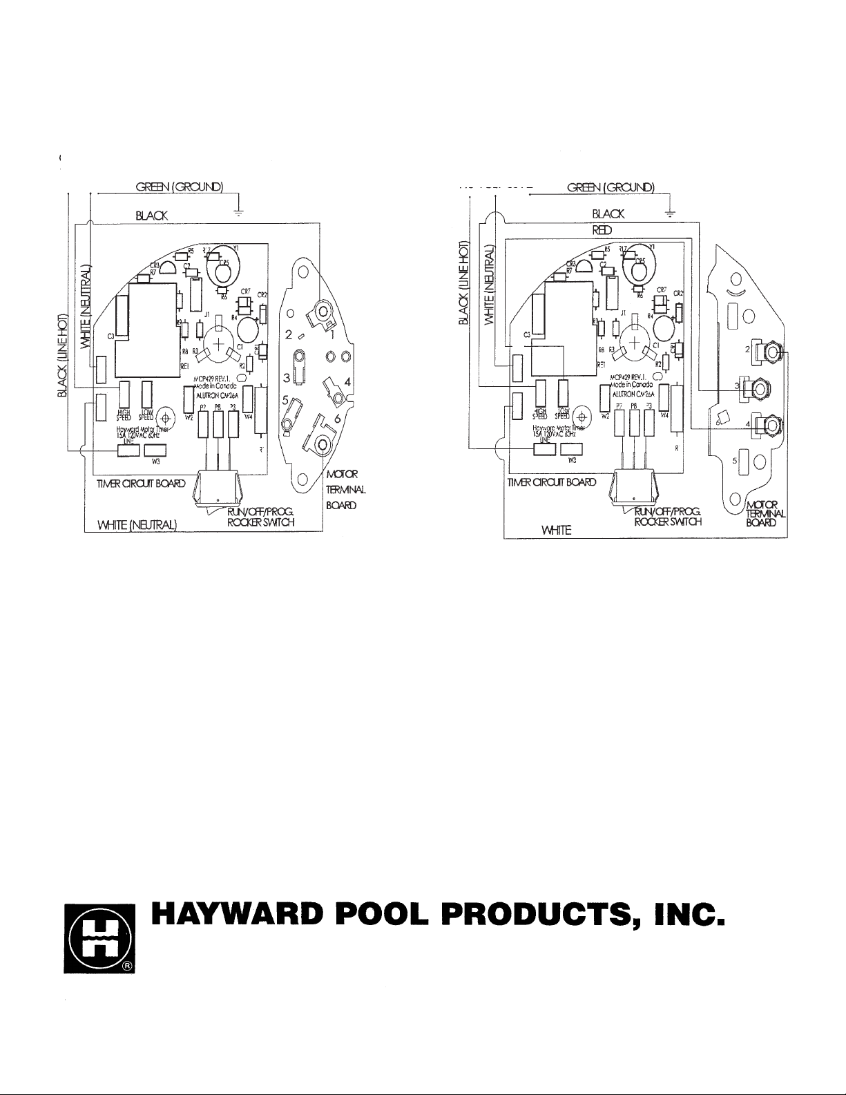
SINGLE-SPEED MOTOR TWO-SPEED MOTOR
Visit our website at www.haywardnet.com
CORDSET OR CONDUIT
115 VOLT 60HZ
CORDSET OR CONDUIT
115 VOLT 60HZ
Hayward Pool Products Europe
Parc Industriel de la Plaine de L’Ain
Allee Des Chenes
01150 Saint Vulbas
France
Hayward Pool Products, Inc.
620 Division Street
Elizabeth, NJ 07207
Hayward Pool Products, Inc.
2875 Pomona Boulevard
Pomona, CA. 91768
Hayward Pool Products Canada
2880 Plymouth Drive
Oakville, Ontario L6H 5R4
© 2004 Hayward Printed in U.S.A.
P2
P6
P4
P5
P1
P1
P2
P4
P5
P6
 Loading...