

Hayward In Ground Pool, Spa Gas Heaters User Manual
51300004201B
IN GROUND POOL/SPA GAS HEATERS
INSTALLATION & OPERATIONS MANUAL
FOR YOUR SAFETY:
WARNING: If the information in these
instructions is not followed exactly, a fire
or explosion may result causing property
damage, injury, or death.
• Do not store or use gasoline or other
flammable vapors or liquids in the vicinity
of this or any other appliance.
WHAT TO DO IF YOU SMELL GAS:
• Do not try to light any appliance.
• Do not touch any electrical switch; do not
use any phone in your building.
• Immediately call your gas supplier from a
neighbor’s phone. Follow the gas supplier’s
instructions. If you cannot reach your gas
supplier, call the fire department.
• Installation and service must be performed
by a qualified installer, service agency or
the gas supplier.
This product must be installed and serviced by
authorized personnel, qualified in pool/spa heater
installation. Improper installation and/or operation
can create carbon monoxide gas and flue gases
that can cause serious injury, property damage,
or death.
CONTENTS Pg
GETTING STARTED 2
INSTALLATION 10
LOCATING THE HEATER 11
ALTITUDE OF INSTALLATION 13
AIR SUPPLY 14
FLUE GAS VENTING 15
GAS SUPPLY 19
WATER PIPING 21
ELECTRICAL CONNECTIONS 24
CHECK-OUT & START-UP 25
CONTROL SETUP 26
GAS TESTING 28
WATER TESTING 31
MAINTENANCE & SERVICE 31
WATER CHEMISTRY 31
WINTERIZATION 32
COMPONENT SERVICE 32
TROUBLESHOOTING 39
PARTS 49
USE ONLY GENUINE REPLACEMENT PARTS 1
SAVE THESE
INSTRUCTIONS
51300004201B
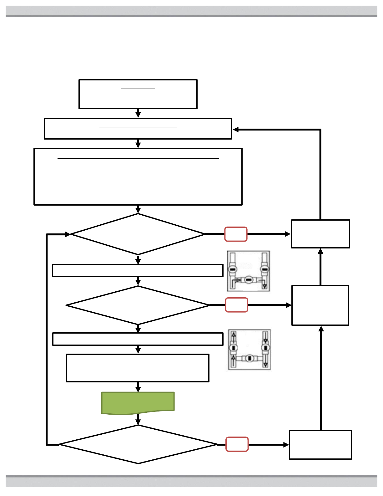
INSTALLATION
Verify that product installation was performed
to local codes and according to this manual.
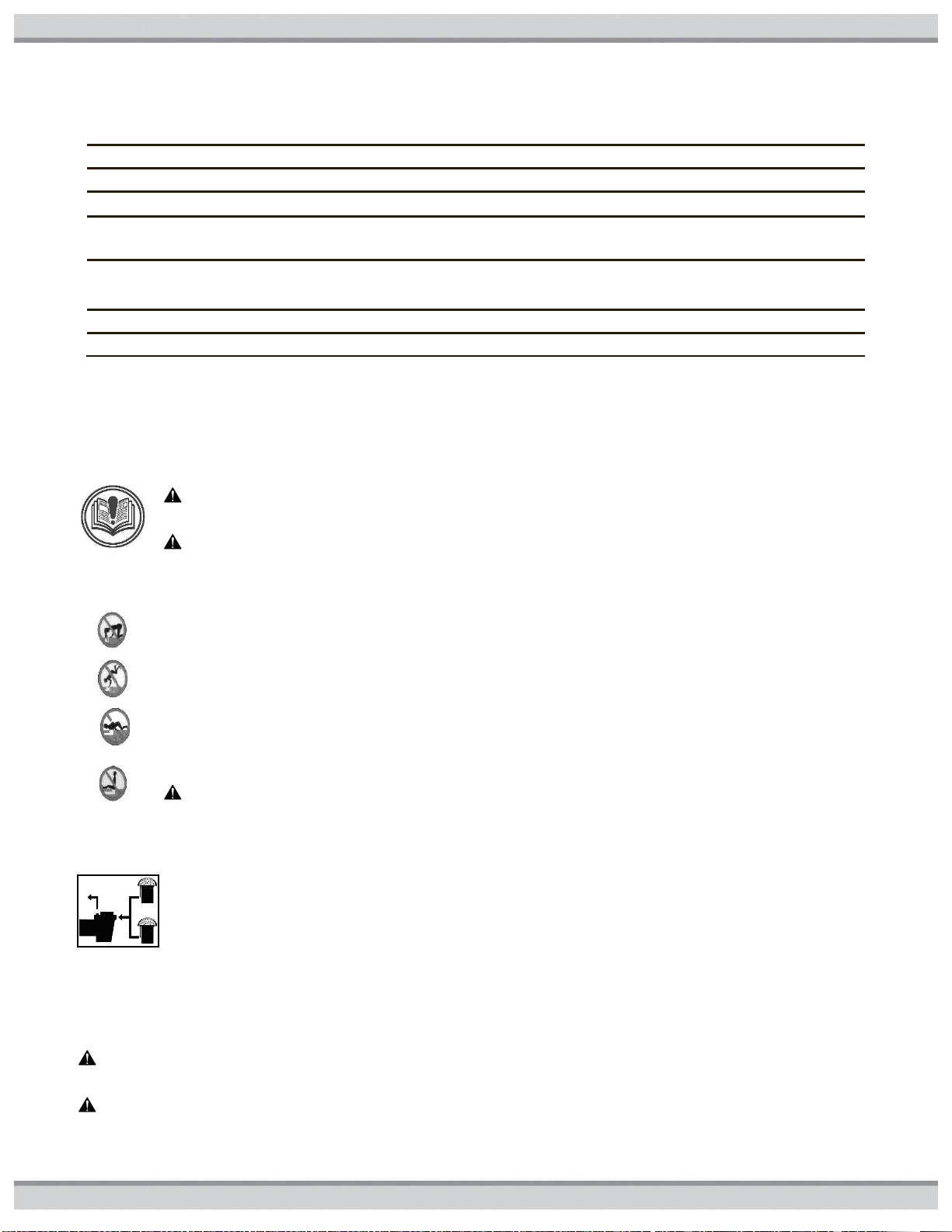
IS POOL/SPA IN
CHEMICAL BALANCE?
INITIAL USE OR SPRING STARTUP
Check all pool / spa water piping. Do not connect product to water piping.
BYPASS TO CLOSED POSITION, WATER DIRECTED TO PRODUCT
TURN ON ELECTRIC POWER AND GAS AS REQUIRED.
START PRODUCT. PROGRAM REQUIRED WATER
TEMPERATURE ON PRODUCT CONTROL PANEL.
IMPORTANT FOR POOL USER HEALTH AND PRODUCT PERFORMANCE
Verify Chlorine or Bromine level every 2-3 days
Verify PH level every week
Verify Alkalinity level every 3-4 weeks (2 weeks if using an Automatic
Chlorine or Bromine Feeder)
Verify Water Hardness and Total Dissolved Solids (TDS) every month (it is
recommended that a pool professional perform this testing)
IS HEATING/COOLING
NEEDED WITHIN 1 WEEK?
SET BYPASS TO
OPEN POSITION,
WATER DIVERTED
FROM PRODUCT
CONNECT WATER PIPING TO PRODUCT, BYPASS TO OPEN POSITION
IS HEATING/COOLING
NEEDED FOR REST OF YEAR?
DISCONNECT
WATER PIPING TO
PRODUCT
TURN OFF ELECTRIC
POWER AND GAS AS
REQUIRED
ENJOY YOUR POOL/SPA
NO
NO
NO
OPEN
PRODUCT
POOL/SPA
CLOSED
PRODUCT
POOL/SPA
GETTING STARTED
WHAT TO EXPECT WHEN OPERATING YOUR POOL HEATER
This flow chart provides guidance to protect pool users and product by maintaining good water quality.
2 USE ONLY GENUINE REPLACEMENT PARTS
51300004201B
Basic safety precautions should always be followed, including the following:
Failure to follow instructions can cause death and/or severe injury.
This is the safety-alert symbol. When you see this symbol on your equipment
or in this manual, look for one of the following signal words and be alert to the
potential for personal injury.
WARNING warns about hazards that could cause death and/or severe
injury or major property damage and if ignored presents a potential hazard.
CAUTION warns about hazards that could cause minor or moderate
personal injury and/or property damage and if ignored presents a potential
hazard. It can also make consumers aware of actions that are unpredictable
and unsafe.
NOTICE indicates special instructions that are important but not related to
hazards.
PLEASE READ BEFORE PROCEEDING
See product rating plate for manufactures information.
USE ONLY GENUINE REPLACEMENT PARTS 3
51300004201B
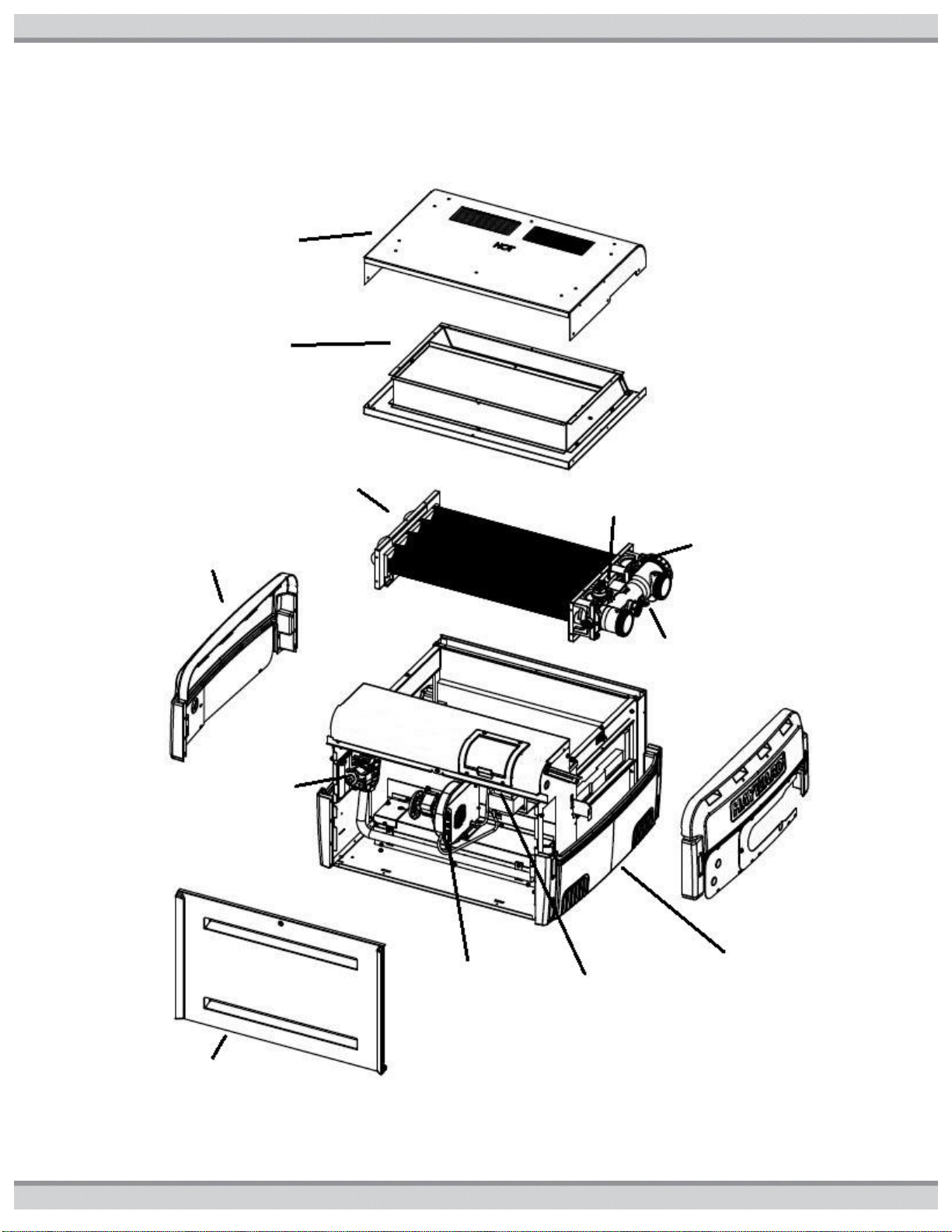
Top Flue Cover
Rain Shield
Assembly
Heat Exchanger
Assembly
Upper Side
Panels
Water Pressure
Switch
Water
Temperature
Switches
Drain Plug or
Relief Valve
Gas
Control
Combustion
Blower
Control Bezel
and Control
Lower Side
Panels
Front Access Panel
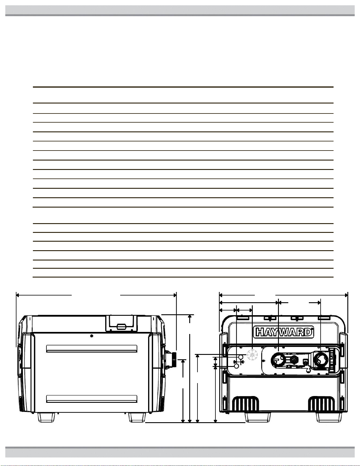
HEATER CONSTRUCTION
Figure1: Sub-Assemblies
4 USE ONLY GENUINE REPLACEMENT PARTS
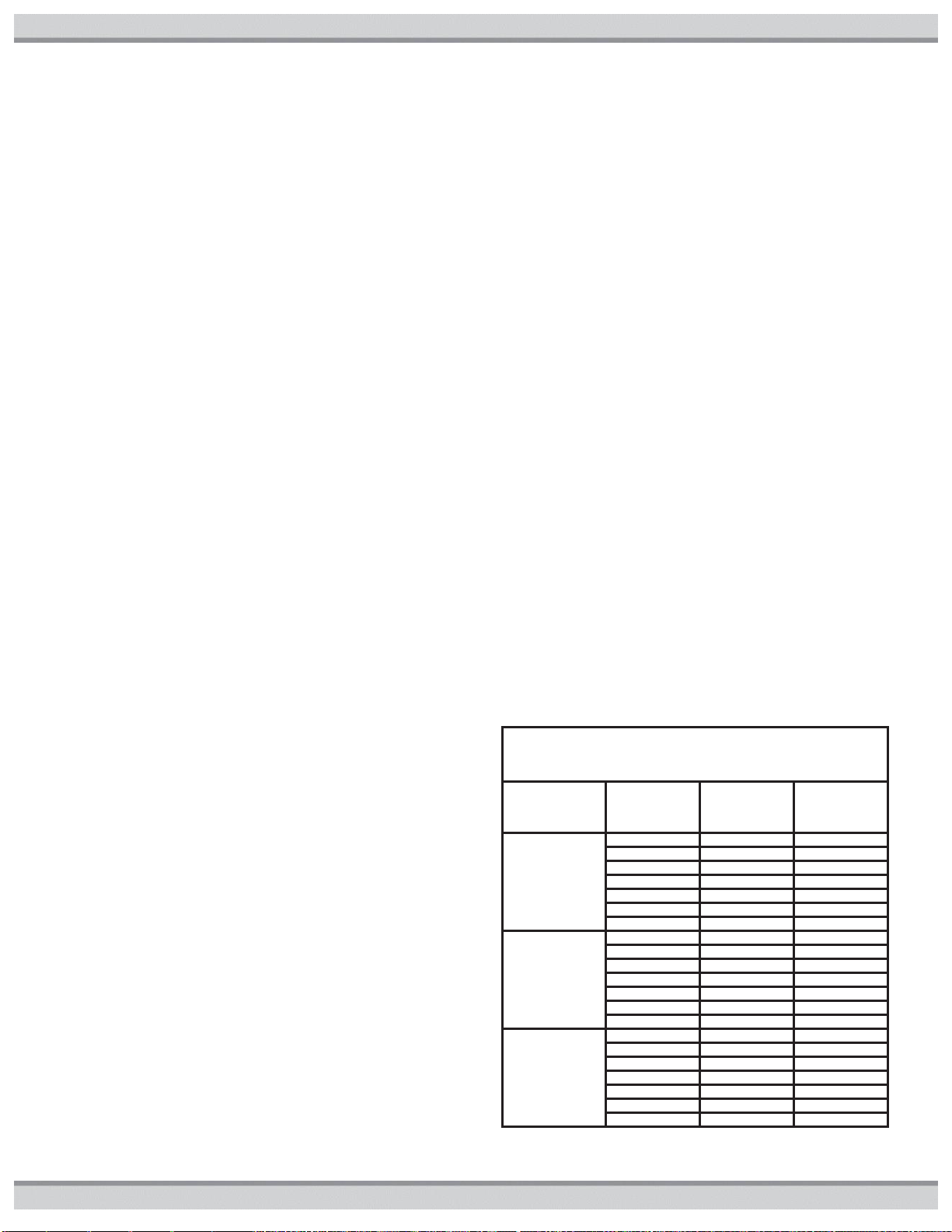
51300004201B
Model
Gas Input
Natural or Propane
Minimum
Water Flow
Thermal
Efficiency
Heater
Width
Heater
Weight
*xxx*
btu/hr
gpm
%
in.
lbs.
150
150,000
20
82.7
19
135
200
199,900
20
83
22
140
250
250,000
25
84
25
165
300
300,000
25
82.7
26
175
350
350,000
30
83
31
195
400
399,900
30
84
34
195
500
500,000
40
83
40
245
250ASME
250,000
25
84
28
195
400ASME
400,000
30
84
36.5
225
500ASME
500,000
40
83
40.5
260
OPERATING PRESSURES
Natural Gas (inwc)
Propane Gas (inwc)
Gas Manifold Pressure*
1.8 - 2.2
6.8 - 7.0
Gas Inlet Pressure, Minimum
4.5
10.0
Gas Inlet Pressure Maximum
10.5
13.0
GAS ORIFICE DRILL SIZES
#25
#43
GAS ORIFICE DRILL SIZES (500kbtu/hr)
#22
2.3mm
Heater Width
22.2
22.2
2.2
2.2
22.2
22.2
22.2
22.2
22.2
2.2
2.2
Table1: SPECIFICATIONS
Features:
120 or 240VAC, 60Hz, 1-phase, 5.5A maximum current
Forced draft combustion with silicon nitride hot surface ignition
Cupronickel water tubes standard
Integral low loss bypass, maximum water flow for all models is 125 GPM
GAS REQUIREMENTS
*Pressure range for allowable heating value variation.
USE ONLY GENUINE REPLACEMENT PARTS 5
51300004201B
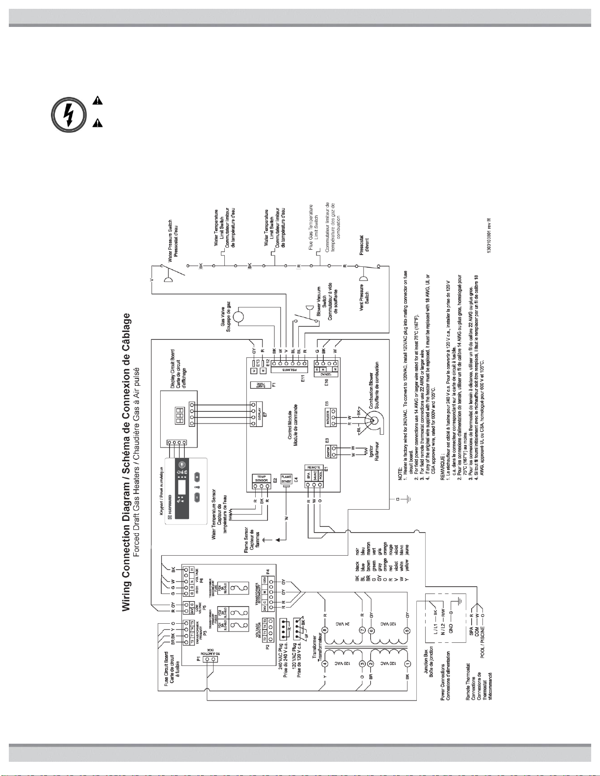
Wiring Connection Diagram
WARNING - Risk of Electric Shock Before working on any electrical equipment, turn off power supply to the
equipment.
WARNING - Risk of Electric Shock. All electrical wiring MUST conform to applicable local codes, regulations,
and the National Electric Code (NEC). Hazardous voltage can cause death, shock, burn, and/or serious property
damage. To reduce the risk of electric shock, do NOT use an extension cord to connect unit to electric supply. Provide
a properly located electrical receptacle. To reduce the risk of electric shock replace damaged wiring immediately.
Locate conduit to prevent abuse from lawn mowers, hedge trimmers and other equipment. Do NOT ground to a gas
supply line.
Figure2: Wiring Diagram
6 USE ONLY GENUINE REPLACEMENT PARTS
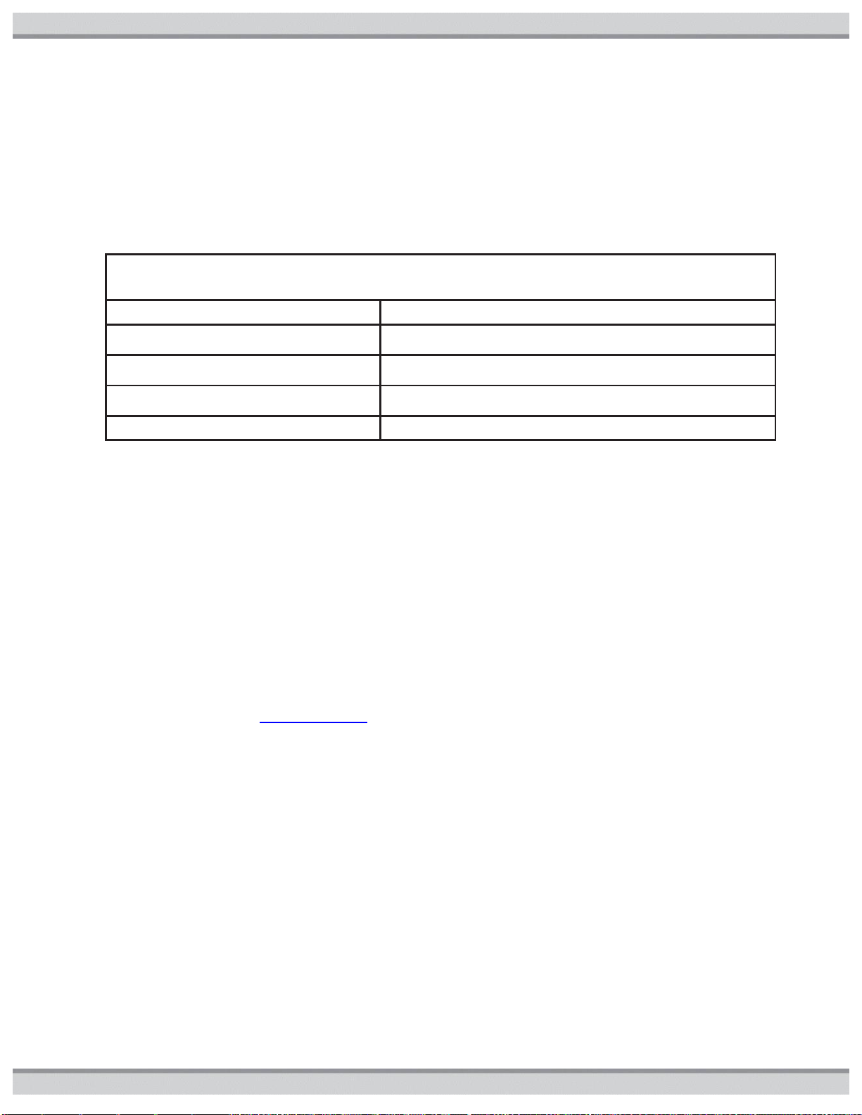
51300004201B
CERTIFICATION CODES AND STANDARDS
USA
CANADA
DESIGN CERTIFIED
CSA
CSA
DESIGN COMPLIANT
ANSI Z21.56
CSA 4.7
INSTALLATION COMPLIANT GAS
NFPA 54/ANSI Z223.1
NFPA 58
CAN/CSA-B149.1-2
INSTALLATION COMPLIANT ELECTRIC
ANSI/NFPA 70
NEC
CSA C22.1 – Canadian
Electrical Code, Part I
EMISSIONS
SCAQMD 1146.2
SHIPPING COMPLIANT
ISTA 3B
ISTA 3B
Table2: CERTIFICATION AND COMPLIANCE
CONFORMANCE WITH CODES: The heater shall be installed in accordance with all local and state codes and with
the requirements of the authority having jurisdiction of the installing site. The heater installation must conform to the
latest edition of the above listed installation codes.
SAFETY INFORMATION
WARNING – Read, Understand, and Follow all instructions in this manual and on the equipment.
Failure to follow instructions can cause severe injury and/or death.
WARNING – Suction Entrapment Hazard.
Suction in suction outlets and/or suction outlet covers which are damaged, broken, cracked, missing, or unsecured
can cause severe injury or death due to the following entrapment hazards:
Hair Entrapment- Hair can become entangled in suction outlet cover.
Limb Entrapment- A limb inserted into an opening of a suction outlet sump or suction outlet cover that is damaged,
broken, cracked, missing, or not securely attached can result in a mechanical bind or swelling of the limb.
Body Suction Entrapment- A negative pressure applied to a large portion of the body or limbs can result in an
entrapment.
Evisceration/ Disembowelment - A negative pressure applied directly to the intestines through an unprotected
suction outlet sump or suction outlet cover which is damaged, broken, cracked, missing, or unsecured can result in
evisceration/disembowelment.
Mechanical Entrapment- There is potential for jewelry, swimsuit, hair decorations, finger, toe or knuckle to be caught
in an opening of a suction outlet cover resulting in mechanical entrapment.
WARNING - To Reduce the risk of Entrapment Hazards:
o When outlets are small enough to be blocked by a person, a minimum of two functioning suction outlets per pump
must be installed. Suction outlets in the same plane (i.e. floor or wall), must be installed a minimum of three feet (3’)
[1 meter] apart, as measured from near point to near point.
o Dual suction fittings shall be placed in such locations and distances to avoid “dual blockage” by a user.
o Dual suction fittings shall not be located on seating areas or on the backrest for such seating areas.
o The maximum system flow rate shall not exceed the flow rating as listed in TABLE1: SPECIFICATIONS.
o Never use Pool or Spa if any suction outlet component is damaged, broken, cracked, missing, or not securely
attached.
o Replace damaged, broken, cracked, missing, or not securely attached suction outlet components immediately.
o Install two or more suction outlets per pump in accordance with latest ASME, APSP Standards and CPSC
guidelines. Follow all applicable National, State, and Local codes.
o Installation of a vacuum release or vent system, which relieves entrapping suction, is recommended.
WARNING – Failure to remove pressure test plugs and/or plugs used in winterization of the pool/spa from the
suction outlets can result in an increase potential for suction entrapment as described above.
WARNING – Failure to keep suction outlet components clear of debris, such as leaves, dirt, hair, paper and other
material can result in an increase potential for suction entrapment as described above.
USE ONLY GENUINE REPLACEMENT PARTS 7
51300004201B
WARNING – Suction outlet components have a finite life, the cover/grate should be inspected frequently and
replaced at least every seven years or if found to be damaged, broken, cracked, missing, or not securely attached.
CAUTION – Components such as the filtration system, pumps and heater must be positioned so as to prevent their
being used as means of access to the pool by young children. To reduce risk of injury, do not permit children to use or
climb on this product. Closely supervise children at all times. Components such as the filtration system, pumps, and heaters
must be positioned to prevent children from using them as a means of access to the pool.
WARNING – Hazardous Pressure. Pool and spa water heating and circulation systems operate under
hazardous pressure during start up, normal operation, and after pump shut off. Stand clear of circulation system
equipment during pump start up. Failure to follow safety and operation instructions could result in violent
separation of the pump housing and cover, and/or filter housing and clamp due to pressure in the system, which
could cause death, severe personal injury and/or property damage. Before servicing pool and spa water circulation
system, all system and pump controls must be in off position and filter manual air relief valve must be in open
position. Before starting system pump, all system valves must be set in a position to allow system water to return
back to the pool. Do not change filter control valve position while system pump is running. Before starting system
pump, fully open filter manual air relief valve. Do not close filter manual air relief valve until a steady stream of
water (not air or air and water) is discharged.
WARNING – Separation Hazard. Failure to follow safety and operation instructions could result in violent
separation of pump and/or filter components. Strainer cover must be properly secured to pump housing with
strainer cover lock ring. Before servicing pool and spa circulation system, filters manual air relief valve must be in
open position. Do not operate pool and spa circulation system if a system component is not assembled properly,
damaged, or missing. Do not operate pool and spa circulation system unless filter manual air relief valve body is in
locked position in filter upper body. Never operate or test the circulation system at more than 50 PSI. Do not
purge the system with compressed air. Purging the system with compressed air can cause components to
explode, with risk of severe injury or death to anyone nearby. Use only a low pressure (below 5 PSI), high volume
blower when air purging the pump, filter, or piping.
WARNING – Risk of Electric Shock. All electrical wiring MUST be in conformance with applicable local
codes, regulations, and the National Electric Code (NEC). Hazardous voltage can shock, burn, and cause death or
serious property damage. To reduce the risk of electric shock, do NOT use an extension cord to connect unit to
electric supply. Provide a properly located electrical receptacle. Before working on any electrical equipment, turn
off power supply to the equipment. To reduce the risk of electric shock replace damaged wiring immediately.
Locate conduit to prevent abuse from lawn mowers, hedge trimmers and other equipment. Do NOT ground to a
gas supply line.
WARNING – Risk of Electric Shock. Failure to ground all electrical equipment can cause serious or fatal electrical shock
hazard. Electrically ground all electrical equipment before connecting to electrical power supply.
WARNING – Risk of Electric Shock. Failure to bond all electrical equipment to pool structure will increase risk for
electrocution and could result in injury or death. To reduce the risk of electric shock, see installation instructions and consult a
professional electrician on how to bond all electrical equipment. Also, contact a licensed electrician for information on local
electrical codes for bonding requirements.
Notes to electrician: Use a solid copper conductor, size 8 or larger. Run a continuous wire from external bonding lug to
reinforcing rod or mesh. Connect a No. 8 AWG (8.4 mm2) [No. 6 AWG (13.3 mm2) for Canada] solid copper bonding wire to the
pressure wire connector provided on the electrical equipment and to all metal parts of swimming pool, spa, or hot tub, and
metal piping (except gas piping), and conduit within 5 ft. (1.5 m) of inside walls of swimming pool, spa, or hot tub.
IMPORTANT - Reference NEC codes for all wiring standards including, but not limited to, grounding, bonding and other
general wiring procedures.
WARNING – Risk of Electric Shock. The electrical equipment must be connected only to a supply circuit that is protected
by a ground-fault circuit-interrupter (GFCI). Such a GFCI should be provided by the installer and should be tested on a routine
basis. To test the GFCI, push the test button. The GFCI should interrupt power. Push reset button. Power should be restored.
If the GFCI fails to operate in this manner, the GFCI is defective. If the GFCI interrupts power to the electrical equipment
without the test button being pushed, a ground current is flowing, indicating the possibility of an electrical shock. Do not use this
electrical equipment. Disconnect the electrical equipment and have the problem corrected by a qualified service representative
before using.
CAUTION – These heaters are intended for use with permanently-installed pools and may be used with hot tubs and spas
if so marked. Do not use with storable pools. A permanently-installed pool is constructed in or on the ground or in a building
such that it cannot be readily disassembled for storage. A storable pool is constructed so that it is capable of being readily
disassembled for storage and reassembled to its original integrity.
8 USE ONLY GENUINE REPLACEMENT PARTS

51300004201B
WARNING – Risk of Hyperthermia. To avoid hyperthermia the following “Safety Rules for Hot Tubs” are recommended by
the U.S. Consumer Product Safety Commission.
1. Spa or hot tub water temperatures should never exceed 104°F [40°C]. A temperature of 100°F [38°C] is considered
safe for a healthy adult. Special caution is suggested for young children. Prolonged immersion in hot water can
induce hyperthermia.
2. Drinking of alcoholic beverages before or during spa or hot tub use can cause drowsiness, which could lead to
unconsciousness and subsequently result in drowning.
3. Pregnant women beware! Soaking in water above 100°F [38°C] can cause fetal damage during the first three
months of pregnancy (resulting in the birth of a brain-damaged or deformed child). Pregnant women should adhere to
the 100°F [38°C] maximum rule.
4. Before entering the spa or hot tub, users should check the water temperature with an accurate thermometer; spa or
hot tub thermostats may err in regulating water temperatures by as much as 4°F (2.2°C).
5. Persons taking medications, which induce drowsiness, such as tranquilizers, antihistamines or anticoagulants, should
not use spas or hot tubs.
6. If the pool/spa is used for therapy, it should be done with the advice of a physician. Always stir pool/ spa water before
entering the pool/spa to mix in any hot surface layer of water that might exceed healthful temperature limits and cause
injury. Do not tamper with controls because scalding can result if safety controls are not in proper working order.
7. Persons with a medical history of heart disease, circulatory problems, diabetes or blood pressure problems should
obtain a physician’s advice before using spas or hot tubs.
8. Hyperthermia occurs when the internal temperature of the body reaches a level several degrees above normal body
temperature of 98.6°F [37°C]. The symptoms of Hyperthermia include: drowsiness, lethargy, dizziness, fainting,
and an increase in the internal temperature of the body.
The effects of Hyperthermia include:
Unawareness of impending danger.
Failure to perceive heat.
Failure to recognize the need to leave the spa.
Physical inability to exit the spa.
Fetal damage in pregnant women.
Unconsciousness resulting in danger of drowning.
DEFINITIONS:
Suction Outlet: The Suction Outlet is a fitting, fitting assembly, cover/grate and related components that provide a means for
water to exit the pool and return into the pump circulating system. This fitting may also be referred to as the “Main
Drain”
Bypass Valves: A valve or series of valves that direct the pool water to flow or not flow through the heater.
CSA: Canadian Standards Association
CGA: Canadian Gas Association
ANSI: American Nation Standards Institute
NFPA: National Fire Protection Association
NEC: National Electric Code
SCAQMD: South Coast Air Quality Management District
ISTA: International Safe Transit Association
Pressure measurement units:
Inches of Mercury (inHg) is typically used with atmospheric pressure measurements.
Pounds per square inch (PSI) is typically used with water “pressure”, “suction” or system measurements.
Inches of Water (inwc) is typically used with gas or air pressure measurements
(1.0 inHg = .49 PSI = 13.5inwc)
USE ONLY GENUINE REPLACEMENT PARTS 9
51300004201B
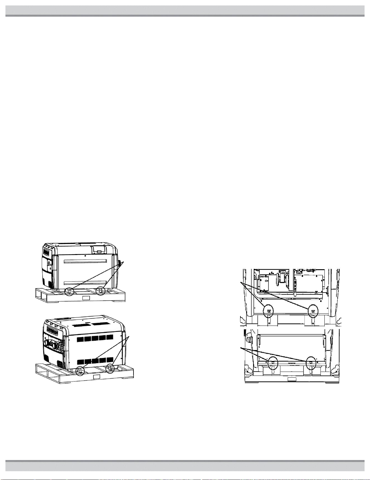
Front shipping
screws and
brackets
Rear shipping
screws and
Front
shipping
screws
Rear
shipping
screws
INSTALLATION:
This manual contains instructions for installation, operation, maintenance, troubleshooting, and parts lists for the proper operation of
the swimming pool/spa/hot tub heaters. It is strongly recommended that the installer read the manual before installing the
swimming pool/spa/hot tub heater. If after reviewing the manual any questions remain unanswered, contact tech services or local
representative. Following heater installation, the installer should leave all manuals with the consumer for future reference.
NOTICE: The installation instructions are intended for the use of a qualified technician, specifically trained and experienced
in the installation of this type of heating equipment. Some states or provinces require that installer be licensed. If this is the
case in the state or province where heater is located, the contractor must be properly certified.
THE USE OF A POOL COVER IS RECOMMENDED. A pool cover reduces heat loss, conserves chemicals, lowers the
load on filter systems and may provide a valuable safety feature
EQUIPMENT INSPECTION: On receipt of the heater, inspect the heater carton(s) for damage. If any carton(s) is damaged,
note it when signing for it. Remove the heater from the carton(s) inspect it and advise the carrier of any damages at once.
NOTICE: Do not drop the heater from a pickup truck tailgate to the ground. This may damage the heater.
UNCRATING THE HEATER: Follow these steps to
remove the shipping carton from the heater:
1. Remove the corrugated carton from the heater. The
carton, top pad, bottom pad, and the four corner posts can
be recycled.
2. There are four (4) external screws (see figure3) used to
secure the heater to the wood pallet. All four must be
removed to separate the heater from the pallet.
Figure3: External Shipping Screw Locations
3. To access the four (4) internal screws (see figure4), open
the front access panel by removing the single top screw.
Then remove the two (2) screws and brackets which hold
the heater base pan to the pallet shown in Figure3. Next
open the rear access panel by removing the four (4)
screws holding this panel. Then remove the two (2)
screws and brackets which hold the heater base pan to
the pallet as shown in Figure3.
4. Lift the heater clear of the corrugated bottom pad and off
of the pallet. Discard bottom corrugated tray and pallet
appropriately.
Figure4: Internal Shipping Screw Locations
10 USE ONLY GENUINE REPLACEMENT PARTS
51300004201B
Table3: Installation Required Clearances (in.)
Heater Panel
Outdoor
Clearance
Indoor
Clearance
Top
Unobstructed
36
Front
18
18
Back*
6
6
Water Side Connection
12
12
Opposite Water Side
Connection
6
6
SPRINKLER HEADS: The heater is designed to handle the wettest weather conditions that are typical of rain and high
humidity. Sprinkler heads force high-pressure water into the unit from the side at an odd angle. Make sure there are no sprinkler
heads near the heater that will spray on or into the unit. Many sprinkler systems are connected to a well system, whose water is
high in minerals, Sulphur, salt and other aggressive contaminates, that will leave a buildup on the unit and electronics causing
corrosion and shortens life.
NOTICE: Damage from sprinkler interaction is not covered under the warranty agreement. Make sure that sprinklers are
placed at a sufficient distance away so that normal wind will not carry the mist to the Heater.
NOTICE: If located in an oceanfront area, the Heater should be placed out of direct spray of sand and salt. This will clog,
damage, and corrode the unit. You may also consider protecting the unit by creating a physical barrier outside of the minimum
clearances between the unit and the prevailing beachfront wind. Damage caused by sand or salt spray is not covered by the
warranty.
LOCATING THE HEATER:
Locate the pool/spa heater in an area where leakage of the heat exchanger or connections will not result in damage to the area
adjacent to the heater or to the structure. When such locations cannot be avoided, it is recommended that a suitable drain pan, with
drain outlet, be installed under the heater. The pan must not restrict airflow. This heater must be installed at least (5) feet from the
inside wall of a pool (in-ground or above-ground)/spa/hot tub unless separated from the pool/spa/hot tub by a solid barrier. The
heater must be installed such that the location of the exhaust gas vent assembly outlet relative to adjacent public walkways,
adjacent buildings, openable windows, and building openings complies with the National Fuel Gas Code (ANSI Z223.1/NFPA 54)
and/or CAN/CGA B149 installation codes.
1. Level surface for proper rain water draining and removal.
2. Suitable electrical supply line. See rating plate on the heater for electrical specifications. A junction box is not needed at the
heater; connections are made inside the unit electrical compartment. Minimum wire size to be selected per NEC.
3. Electric disconnect switch that will interrupt all power to the unit. This switch MUST be within line of sight of the heater.
4. The heater does not require additional vent piping when installed outdoors.
5. Do not install in a location where growing shrubs may in time obstruct a heater’s combustion air and venting areas.
6. Do not install this appliance under an overhang less than 72in from the top of the appliance. The area under the overhang must
be open on (3) sides.
7. Do not install the heater where water spray from ground level can contact the heater. The water could reach the controls
causing electrical damage.
8. Do not install under a deck.
9. Do not install within 24in of any outdoor HVAC equipment.
10. Do not install where water may run-off a roof into the heater. A gutter may be needed to protect the heater.
CAUTION: Make sure the heater is not located where large amounts of water may run-off from the roof into the unit. Sharp
sloping roofs without gutters will allow massive amounts of rainwater, mixed with debris from the roof to be forced through the
unit. Failure to follow the instructions may result in property damage and void warranty.
11. Any enclosure around the heater must provide a combustion air vent large enough to accommodate input ratings of all gas
appliances in the enclosure. See AIR SUPPLY section for more detail
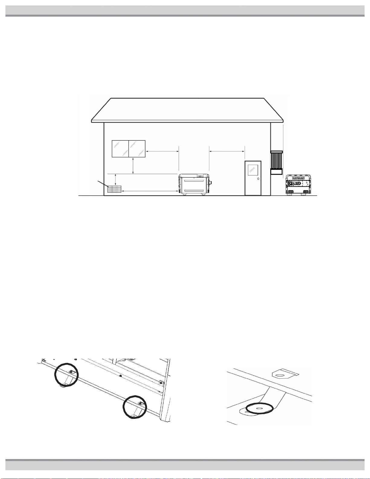
12. For minimum exhaust vent clearances for all building openings, including but not limited to vented eaves, doors, windows, or
gravity inlets, see Figure5. In Canada, the heater must be installed with the top of the vent at least 10 feet (3m) below, or
to either side of, any opening into a building.
OUTDOOR AND INDOOR INSTALLATION AND SERVICE
CLEARANCES: For both outdoors and indoors installations,
the installation clearances from combustible materials and
service clearances shown in Table3 and Figure5 must be
maintained. Do not install heater in a closet or enclosed space
(consult NFGC)
*If the heater is to be installed with vinyl siding at back,
increase the clearance in Table3 to 12 inches to avoid potential
discoloration of siding
USE ONLY GENUINE REPLACEMENT PARTS 11
51300004201B
4 ft.
minimum
4 ft.
minimum
4 ft.
minimum
3 ft.
minimum
10 ft. minimum
Force Air
Inlet
Free
from rain
run off or
blockage
from
above
EQUIPMENT PAD: Place the heater on a level surface such as concrete or a fabricated slab (pad). This allows proper
drainage of condensation and rainwater from the base of the unit. If possible, the pad should be placed at the same level or slightly
higher than the filter system equipment pad.
FLOORING: This heater may be installed on either non-combustible flooring or combustible flooring that does not reduce the
bottom clearance of the heater. Ultralite™ or equivalent concrete-over-foam HVAC pads are acceptable.
Figure5: Outdoor Minimum Clearances
ANCHORING: The heater is equipped for installation of factory supplied tie-down brackets when required by local codes.
Follow all relevant Local, State and National requirements regarding wind load anchoring. The brackets are shipped in the
consumer kit. You will need the following to complete the installation:
Tie-down brackets (FACTORY-SUPPLIED, qty = 4)
Sheet metal screws (FACTORY-SUPPLIED, qty = 4)
Concrete tapping screws (FIELD-SUPPLIED, Tapcons®, qty = 4, stainless steel, size to be ¼”diameter with a minimum
length of 1-1/2”)
Fender washers (FIELD SUPPLIED, stainless steel, qty = 4, size to be at least 1-1/2”)
INSTALLING TIE-DOWN BRACKETS:
1. Locate the tie-down brackets and the sheet metal screws.
2. Obtain the Tapcons®. Be sure the overall length of the concrete tapping screw is at least1-1/2”.
3. Remove the front (1 screw) and rear access panel (4 screws).
4. Position the heater on the pad so that all Tapcons® can “bite” into the pad. Observe local codes regarding pad construction,
some jurisdictions specify a minimum thickness for concrete pads.
5. Position the tie-down brackets into the slots in the front of the heater base pan so they are positioned as shown in Figure6. Install
the sheet metal screws through the holes in the bracket to secure the bracket to the heater base pan.
6. Install the Tapcons® through the inner set of holes in the tie-down brackets into the pad (see figure7).
7. Repeat Steps 6 & 7 at the rear of the heater.
8. Tie down is completed when (4) brackets are secured to the heater and the pad. Re-install the access panels in locations (front
and rear), front shown
Figure6: Tie-Down Installation Locations
Figure7: Use 2nd Hole for Ground Mount of
Tie-Down Brackets with 2 Holes
12 USE ONLY GENUINE REPLACEMENT PARTS
Install supplied screws at these locations.
51300004201B
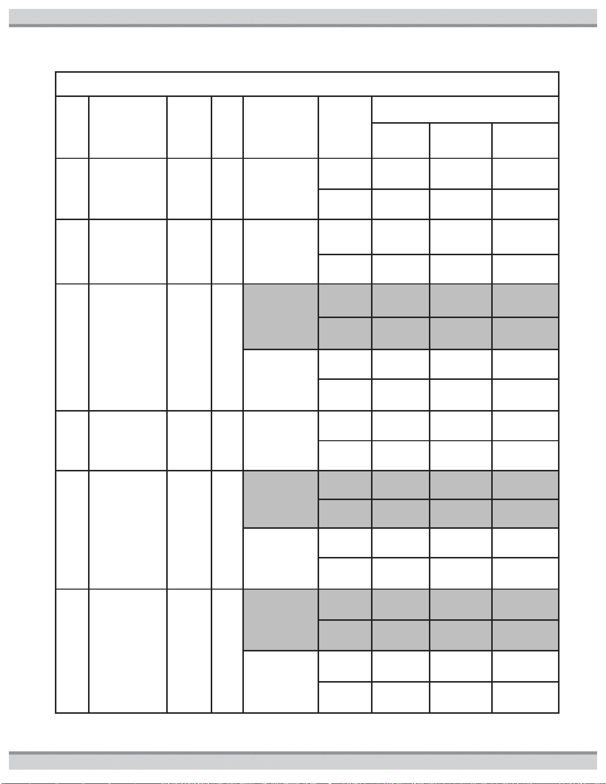
Table4 High Altitude Conversions in (ft.)
Model
Outdoor Installation
Indoor Installation *
No
Modifications
to Heater
Included
Conversion
Plate Installed
Kit
FDXLHAK1930
Installed
No
Modifications
to Heater
Included
Conversion Plate
Installed
Kit
FDXLHAK1930
Installed
150FDN
7,700
N/A
10,100
10,100
N/A
N/A
150FDP
7,700
N/A
10,100
2,000
10,100
N/A
200FDN
10,100
N/A
N/A
10,100
N/A
N/A
200FDP
5,400
10,100
N/A
2,000
10,100
N/A
250FDN
5,400
10,100
N/A
2,000
10,100
N/A
250FDP
2,000
7,700
10,100
2,000
7,700
10,100
300FDN
10,1001
N/A
N/A
10,100
N/A
N/A
300FDP
2,000
10,100
N/A
2,000
10,100
N/A
350FDN
2,000
10,100
N/A
2,000
10,100
N/A
350FDP
2,000
7,700
10,100
2,000
7,700
10,100
400FDN
10,100
N/A
N/A
10,100
N/A
N/A
400FDP
2,000
7,700
10,100
2,000
7,700
10,100
500FDN
10,100
N/A
N/A
10,100
N/A
N/A
500FDP
5,400
7,700
10,100
5,400
7,700
10,100
GAS CONVERSION:
Where permitted by local codes, the factory-installed gas train may be changed from natural gas to propane or from propane to
natural gas, using the appropriate conversion kits. Gas conversions are to be performed only by a qualified service agency. Detailed
instructions are included with each kit.
ALTITUDE OF INSTALLATION:
Heaters may be installed at any altitude up to 10,100 ft. above sea level, provided the appropriate modification(s) are performed.
The altitudes which require modification vary depending on the model. Parts necessary to convert the heater for outdoor installation
at altitudes up to 7,700 ft. (minimum) are included with the heater.
WARNING: Failure to comply with the appliance and vent package installation instructions and service instructions in
this manual may result in equipment damage, fire, asphyxiation, or carbon monoxide poisoning. Exposure to products of
incomplete combustion (carbon monoxide) can cause cancer and birth defects or other reproductive harm.
Conversion is accomplished by replacement of the blower air inlet plate, and for indoor applications, installation of the appropriate
vent pressure switch. The blower air inlet plates are clearly marked with the compatible heater model(s), vent configuration(s), and
altitude range(s). Care should be taken to verify the correct plate and vent pressure switch is being used to ensure proper heater
performance. The vent pressure switch will be provided with the indoor adapter kit, or if you have an older indoor adapter kit, order
p/n FDXLVPS1931 for the high-altitude indoor vent pressure switch. Table4 lists the maximum altitudes for which each model is
designed with: a) no modifications, b) the included conversion plate installed, and c) the accessory conversion kit FDXLHAK1930
installed (sold separately).
* All indoor installations at altitudes above 2,000 require a vent pressure switch to be installed in addition to the blower inlet plate.
The vent pressure switch is included with the appropriate indoor vent kit (UHXNEGVT1xxx or UHXPOSHZ1xxxx), or the highaltitude vent pressure switch kit FDXLVPS1931.
USE ONLY GENUINE REPLACEMENT PARTS 13
51300004201B
Table5 Combustion and Ventilation Air
Requirements (sq. in.)*
Free Area per
Total Btu
Requirement
Total
Input
(Btu/hr)
Combustion
Air Free Area
Required
Ventilation
Air Free Area
Required
1
sq. in. per
1,000 Btu/hr
(Indoor Air)
150,000
150
150
200,000
200
200
250,000
250
250
300,000
300
300
350,000
350
350
400,000
400
400
500,000
500
500
1
sq. in. per
2,000 Btu/hr
(Outdoor Air thru
Horz duct)
150,000
75
75
200,000
100
100
250,000
125
125
300,000
150
150
350,000
175
175
400,000
200
200
500,000
250
250
1 sq. in. per
4,000 Btu/hr
(Outdoor Air
direct or thru Vert
duct )
150,000
37.5
37.5
200,000
50
50
250,000
62.5
62.5
300,000
75
75
350,000
87.5
87.5
400,000
100
100
500,000
125
125
High-Altitude Conversion Procedure:
1. Identify the altitude of the installation site. This may be done using a GPS device, or by looking up the altitude for the geographic
location. Altitudes for all locations in the United States and Canada may be found using the zip/postal code database at
www.zip-codes.com. If the altitude for the installation site is greater than 10,100 ft., the heater may not be installed. Note that if
installing outdoors, some heaters may be compatible with your altitude without modification. Table4 lists the altitude ranges for
heaters without modification. All indoor heaters installed above 2,000 ft. require the appropriate vent pressure switch, see indoor
installation kit instructions.
2. Select the appropriate blower air inlet plate to use based on the heater model, vent configuration (outdoor or indoor), and altitude
needed. Extra plate(s) are included with the heater, packaged in the plastic bag with this manual. Each plate has a label which
identifies which model(s), vent configuration(s), and altitude range(s) for which it is designed. Table4 lists the maximum
installation altitudes using the included conversion plate(s). If installing above 7,700 ft., the high-altitude kit FDXLHAK1930 (sold
separately) may be necessary.
3. If installing indoors, select the appropriate high-altitude indoor vent pressure switch from the indoor adapter kit or from the
FDXLVPS1931 kit. Each switch has a label which identifies which model(s) and altitude range(s) for which it is designed.
4. If connected, turn pump, main gas valve, and heater power off, remove heater front access door.
5. Remove the 4 #10 hex head screws that fasten the blower air inlet plate to the blower, and remove the blower air plate and
discard. Save the 4 screws as they will be needed to install the new plate. See Figure29: Blower
6. Install the appropriate blower plate from the kit using the 4 screws. It may be helpful to drive the screws in and out of the plate
outside of the heater first to “thread” the holes before installing it in the heater.
7. If the installation is configured for indoor venting, a special high-altitude vent pressure switch must be installed. Follow the
instructions provided in listed vent kits (see Tables 6 and 9), and use the appropriate blower air inlet plate and vent pressure
switch for your altitude.
8. Re-install heater front door, if connected, turn pump, main gas valve, and heater power back on.
9. Activate heater and check for proper operation.
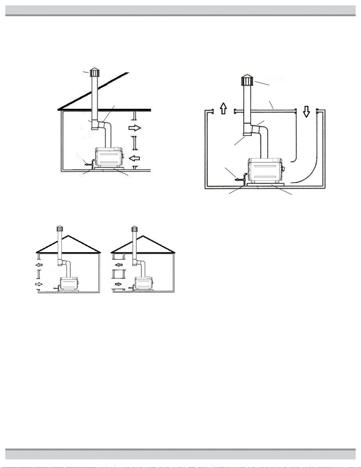
AIR SUPPLY:
Indoor installations and outdoor shelters (confined spaces) must be provided with adequate combustion and ventilation air openings
to assure proper heater operation. These openings must be sized according to the requirements stated in paragraphs below (ALL
AIR SUPPLY FROM INSIDE THE BUILDING or ALL AIR SUPPLY FROM OUTDOORS whichever applies to the installation). These
air openings must never be obstructed when heater is in operation. These confined spaces shall be provided with 2 permanent
openings, one commencing within 12 inches of the bottom and one commencing within 12 inches of the top of the enclosure. The
openings shall communicate directly or by ducts, with the outdoors or spaces (crawl or attic) that freely communicate with the
outdoors. Ducts shall be of the same cross-sectional area as the free area of the openings to which they connect. The minimum
dimension of rectangular air ducts shall not be less than 3 inches. When air blowers are used in spa/hot tub installations and are
located in proximity to the heater, caution must be observed to ensure sufficient combustion air is available to the heater for proper
combustion. A separate blower air duct is recommended. Table 3 indoor clearances apply.
ALL AIR SUPPLY FROM INSIDE THE BUILDING: The
confined space shall be provided with 2 permanent openings
communicating directly with an additional room(s) of sufficient
volume so that the combined volume of all spaces meets the
criteria for an unconfined space (a space whose volume is not
less than 50 cubic feet per 1,000 btu/hr of total input all gas
utilization equipment installed in the combined space shall).
Each opening shall have a minimum free area of 1 square inch
per 1,000 btu/hr of the total input, but not less than 100 square
inches. See Table5 and Figure8.
ALL AIR SUPPLY FROM OUTDOORS: When communicating
with the outdoors through horizontal ducts, each opening shall
have a minimum free area of 1 square inch per 2,000 btu/hr of
total input See Table5 and Figure9B. When communicating
with the outdoors (either directly or through vertical ducts),
each opening shall have a minimum free area of 1 square inch
per 4,000 btu/hr of total input rating of all equipment in the
enclosure. See Table5 and Figure9A. When installing a heater
below ground (in a pit, for use with Natural Gas only),
combustion and ventilation air openings must be provided as
shown in Figure10.
14 USE ONLY GENUINE REPLACEMENT PARTS
*For detailed methods of providing combustion and ventilation air, see
latest edition of the National Fuel Gas Code (ANSI Z223.1/NFPA 54).
51300004201B
Ventilation
Air
Combustion
Air
Ventilation
Air
Combustion
Air
Drip
Tee
Vent Cap
Ground
Rise 1in/ft.
Gas Shut Off
Sediment Trap
Level Floor/Slab
Rise 1in/ft.
Drip
Tee
Vent Cap
Gas Shut
Off
Sediment Trap
Level Floor/Slab
Figure8: Air from Inside Building Installation
1 square inch per 1,000 btu/hr of the total input
Table3 Indoor Clearance Apply
Figure9: Air from Outside Building Installation
A)1 square inch per B)1 square inch per
4,000 btu/hr of 2,000 btu/hr of
total input total input
Figure10: Air Below-Ground
(Pit for Natural Gas only Installations)
1 square inch per 4,000 btu/hr of total input
Table3 Indoor Clearance Apply
FLUE GAS VENTING:
For installation outdoors, no additional venting is required for operation. Ensure top of unit remains unobstructed.
INDOOR INSTALLATION WITH NEGATIVE (CATI) OR POSITIVE (CATIII) PRESSURE VENTING SYSTEMS: The heater is
designed such that it may be vented using either a negative-pressure or a positive-pressure venting system. The appropriate
system of venting for a particular site will depend on many factors such as vent termination needs (horizontal/vertical), clearance of
vent termination, length of vent and the cost of venting system. Table6 (CATI) and Table9 (CATIII) list the required indoor venting
kits available for each system. Multiple forced- or induced-draft units should never be vented using common venting or vent
terminations. Never common vent this heater with other gas-burning appliances.
NEGATIVE PRESSURE (VERTICAL ONLY, CATI) VENTING:
NEGATIVE PRESSURE CATI VENT SIZING: Size the vent pipe according to the venting Tables in the National Fuel Gas Code
(ANSI Z223.1/NFPA 54) for a Category I gas appliance using single-wall or double-wall (Type B) gas vent. Vent pipe diameter
should not be less than the size of the vent pipe adapter on the heater with the appropriate vent kit adapter installed (see Table6).
Single-wall vent may be used in conditioned spaces only. Clearance to combustible materials for single-wall vent is 9 inches.
Double-wall (Type B) vent may be used in conditioned spaces, but must be used in non-conditioned spaces. Clearance to
combustible materials for double-wall vent is 6 inches. Smaller clearances may be available; consult the National Fuel Gas Code.
USE ONLY GENUINE REPLACEMENT PARTS 15
51300004201B
Table6 Negative-Pressure (CATI) Indoor Vent Kits with Vent Pipe & Terminal Specifications
Models
Indoor Vent Kit
Part Number
Vent
Dia(in)
Description
Vent Pipe
Application
Vent Pipe
Material
Vent
Termination
Requirement
150
UHXNEGVT11506
6
Indoor Vent
Adapter Kit,
Negative
Pressure
CATI, Vertical
Venting
Applications
Vent pipe to be
installed according to
the venting Tables in
the National Fuel
Gas Code (ANSI
Z223.1/NFPA 54) for
a Category I gas
Single or
Double Wall,
Galvanized,
Non-Sealed
Vent Pipe
Vertical
Only
200
UHXNEGVT12006
6
250
UHXNEGVT12506
6
300
UHXNEGVT13008
8
350
UHXNEGVT13508
8
400
UHXNEGVT14008
8
500
UHXNEGVT15008
8
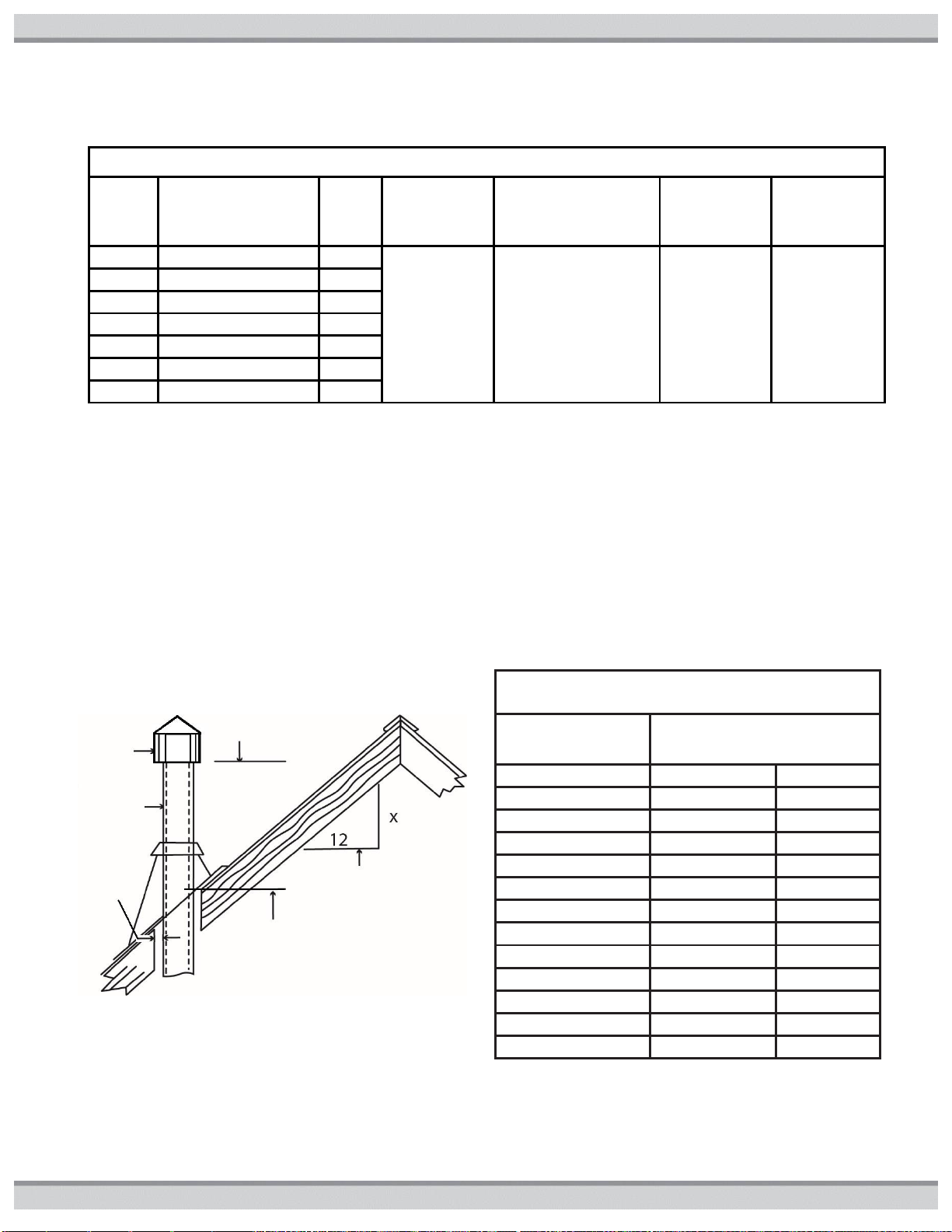
Table7 Height Requirements for Negative
Pressure (CATI) Vent Caps (see Figure11)
Roof
Slope
Min. Height
H
from Roof to
Lowest Discharge Opening
(ft.) (m)
Flat to 6/12
1.0 0.30
Over 6/12 to
7/12
1.25 0.38
Over 7/12 to
8/12
1.5 0.46
Over 8/12 to
9/12
2.0 0.61
Over 9/12 to
10/12
2.5 0.76
Over 10/12 to
11/12
3.25 0.99
Over 11/12 to
12/12
4.0 1.22
Over 12/12 to
14/12
5.0 1.52
Over 14/12 to
16/12
6.0 1.83
Over 16/12 to
18/12
7.0 2.13
Over 18/12 to
20/12
7.5 2.27
Over 20/12 to
21/12
8.0 2.44
Listed
Cap
Lowest Discharge
Min. Height (H) from Roof to
Lowest Discharge Opening
Roof Slope at X/12
CATI MECHANICAL DRAFT SYSTEMS: Vent systems requiring power venting must use mechanical draft systems listed in
accordance with UL378 Draft Equipment. Selection of power venter and required clearances from combustible materials must
follow draft equipment manufacture’s instructions, National Fuel Gas Code, local codes and the information in this manual.
NEGATIVE PRESSURE CATI VENT TERMINATION: Any vent extending through a roof or wall must be listed double-wall (Type B)
vent, and pass through an approved roof jack, or roof thimble. A listed vent cap must be used. Terminations for Gas vents with
listed 12in or less diameter size and located not less than 8ft from a vertical wall or similar building feature shall terminate per
Figure11 and Table7 using the roof pitch to find the minimum termination height value of H. Terminations for Gas vents with listed
12in or less diameter size located less than 8ft from a vertical wall or similar building feature shall terminate not less than 2ft above
the highest point where they pass through the roof and not less than 2ft above any portion of a building within 10ft horizontally
Figure11: Minimum Height from Roof
for Vent Cap
16 USE ONLY GENUINE REPLACEMENT PARTS
51300004201B
Table8 Positive-Pressure (CATIII) Indoor Vent Maximum Vent Lengths
Using Specified Positive Pressure Indoor Vent Kits
Number of 90- degree Elbows
Maximum Vent Pipe Length horizontal & vertical (ft.)
0
50 1 50 2 40
3
30
M&G DuraVent Inc.
Selkirk Corporation
6 Jupiter Ln.
Heatfab Division
Colonie, NY 12205
OR
130 Industrial Blvd
(800) 835-4429
Turners Falls, MA 01376
www.duravent.com
(800) 772-0739
DuraVent FasNSeal (W2)
www.heatfab.com
Heatfab Saf-T Vent EZ
Seal (CI Plus)
POSITIVE PRESSURE (HORIZONTAL OR VERTICAL, CATIII) VENTING:
When installed according to the following instructions, heaters meet the criteria for category III venting.
VENT SIZING: Vent pipe diameter must match the vent pipe diameter on the heater (see Table9). The vent pipe must be single or
double-wall stainless steel sealed vent as listed in Table9. Double-wall vent must be used in non- conditioned spaces. The
maximum total length of vent pipe, and number of 90-degree elbows cannot exceed the limits specified in Table8.The venting
system must be installed in accordance with the vent manufacturer’s installation instructions and guidelines. The installer is urged to
visit the vent system manufacturer’s website (see below) and review the installation information found there.
VENT TERMINATION: The vent system must terminate with a vent terminal approved for this pool heater. Termination may be
either horizontal or vertical. See Table9a for approved vent terminals and 9b for termination locations.
OBTAINING VENT PIPE AND TERMINATIONS: A variety of vent components, including terminals, elbows, and straight lengths,
are available for use with this appliance. Approved parts are listed in Table9 and in the service parts section in the back of this
manual. If you need more specialized fittings, you may order them directly from the manufacturer, or one of their authorized
dealers. To locate an authorized dealer for venting parts, contact the appropriate manufacturer at:
Notes for Table9 Positive-Pressure (CATIII) Indoor Vent Kits with Vent Pipe & Terminal Specifications
* For Heatfab single-wall vent pipe section length, “x” to be: 1, 2, 4, 5, or 7, where 1=6 inches, 2=12 inches, 4=18 inches, 5=24 inches, and
7=36 inches.
** For Heatfab double-wall vent pipe section length, “x” to be: 06, 09, 12, 18, 24, or 36, indicating the length of the vent pipe section in
inches.
† For DuraVent vent pipe section length, “x” to be: 6, 12, 18, 24, or 36, indicating the length of the vent pipe section in inches.
‡ For these horizontal terminals, the wall penetration is included from the vent manufacturer. On all others, it must be ordered separately.
USE ONLY GENUINE REPLACEMENT PARTS 17
51300004201B
Table9 Positive-Pressure (CATIII) Indoor Vent Kits with Vent Pipe & Terminal Specifications
Heater
Model
Indoor Vent Kit
Part Number
Maximum
Installation
Altitude (ft.)
Vent
Pipe
Dia.
(in)
Appliance
Adapter
Vent Pipe
Type
Heatfab Saf-T Vent EZ Seal (CI Plus) or
DuraVent FasNSeal (W2)
Vent Pipe
Part
Number
Horizontal
Vent Terminal
Part Number
Vertical Vent
Terminal
Part Number
150
200
UHXPOSHZ11506
UHXPOSHZ12006
10,100
6
Heatfab adapter
included in kit
Single-Wall
HeatfabP/N
960x *
HeatfabP/N
9614TERM
HeatfabP/N
5600CI
Double-Wall
HeatfabP/N
CCA06Lx **
HeatfabP/N
9614TERM
HeatfabP/N
CCA06RC
250
UHXPOSHZ12506
10,100
6
Heatfab adapter
included in kit
Single-Wall
HeatfabP/N
960x *
HeatfabP/N
5690CI ‡
HeatfabP/N
5600CI
Double-Wall
HeatfabP/N
CCA06Lx **
HeatfabP/N
CCE06WP ‡
HeatfabP/N
CCA06RC
250FDN
(NAT
ONLY)
UHXPOSHZ12504
2,000
4
UHXDVA004
(4” Duravent
adapter)
Single-Wall
DuraVentP/N
FSVLx04 †
DuraVentP/N
FSTT4
DuraVentP/N
FSRC4
Double-Wall
DuraVentP/N
W2-x04 †
DuraVentP/N
FSTT4
DuraVentP/N
W2-RC4
UHXHFA004
(4” Heatfab
adapter)
Single-Wall
HeatfabP/N
940x *
HeatfabP/N
9414TERM
HeatfabP/N
5400CI
Double-Wall
HeatfabP/N
CCA04Lx **
HeatfabP/N
9414TERM
HeatfabP/N
CCA04RC
300
350
400
UHXPOSHZ13008
UHXPOSHZ13508
UHXPOSHZ14008
10,100
8
Heatfab adapter
included in kit
Single-Wall
HeatfabP/N
980x *
HeatfabP/N
5890CI ‡
HeatfabP/N
5800CI
Double-Wall
HeatfabP/N
CCA08Lx **
HeatfabP/N
CCE08WP ‡
HeatfabP/N
CCA08RC
400
UHXPOSHZ14006
2,000
6
UHXDVA006
(6” Duravent
adapter)
Single-Wall
DuraVentP/N
FSVLx06 †
DuraVentP/N
FSTT6
DuraVentP/N
FSRC6
Double-Wall
DuraVentP/N
W2-x06 †
DuraVentP/N
FSTT6
DuraVentP/N
W2-RC6
UHXHFA006
(6” Heatfab
adapter)
Single-Wall
HeatfabP/N
960x *
HeatfabP/N
9614TERM
HeatfabP/N
5600CI
Double-Wall
HeatfabP/N
CCA06Lx **
HeatfabP/N
9614TERM
HeatfabP/N
CCA06RC
500
UHXPOSHZ15006
10,100
6
UHXDVA006
(6” Duravent
adapter)
Single-Wall
DuraVentP/N
FSVLx06 †
DuraVentP/N
FSTT6
DuraVentP/N
FSRC6
Double-Wall
DuraVentP/N
W2-x06 †
DuraVentP/N
FSTT6
DuraVentP/N
W2-RC6
UHXHFA006
(6” Heatfab
adapter)
Single-Wall
HeatfabP/N
960x *
HeatfabP/N
9614TERM
HeatfabP/N
5600CI
Double-Wall
HeatfabP/N
CCA06Lx **
HeatfabP/N
9614TERM
HeatfabP/N
CCA06RC
18 USE ONLY GENUINE REPLACEMENT PARTS
 Loading...