

Hayward hydrorite uvo3 Owner's Manual

HydroRite UVO3
2” Residential UV/Ozone Sanitizing System
Owner’s Manual
092596 RevA
Contents
Safety Instructions..........1
Before you Begin.............2
Installation.....................3
Operation.......................7
Maintenance...................7
FAQs.............................10
Troubleshooting............11
Replacement Parts.........12
Warranty.......................14
Model: HYD-UVO
USE ONLY HAYWARD GENUINE REPLACEMENT PARTS
Hayward Pool Products
620 Division Street, Elizabeth NJ 07207
Phone (908)-355-7995
www.hayward.com

IMPORTANT SAFETY INSTRUCTIONS
When installing and using this electrical equipment, basic safety precautions should
always be followed, including the following:
READ AND FOLLOW ALL INSTRUCTIONS
This product should be installed by a professional service technician or similar person who is qualied in electrical
equipment installation. Improper installation and/or operation could cause serious personal injury, property damage or
death. Improper installation and/or operation will void the warranty.
• The device must be connected only to a supply circuit that is protected by a Ground Fault Circuit Interrupter
(GFCI). FAILURE TO CONNECT THIS DEVICE TO A GFCI SUPPLY CIRCUIT COULD RESULT IN ELECTRICAL
SHOCK CAUSING SERIOUS BODILY INJURY, INCLUDING DEATH.
• WARNING - Disconnect all AC power during installation.
• CAUTION - To prevent possible re or electrical shock, use only replacement lamp specied by the manufacturer.
• A bonding lug is provided on the external surface. To reduce the risk of electric shock, connect the local common
bonding grid in the area of the swimming pool, spa, or hot tub to these terminals with an insulated or bare copper
conductor not smaller than 8 AWG US / 6 AWG Canada.
• Replace damaged cords immediately.
• Lamps and quartz sleeves are made of glass and are extremely delicate. Care should be taken when handling or
replacing these components. Wear cotton gloves when handling lamps or sleeves. Hold bulbs by the ends only.
Never touch the glass with bare hands. Wipe any ngerprints from lamps and sleeves with alcohol.
• CAUTION - this device is for swimming pool use only. Do not use this device for potable (drinking) water sanitiza-
tion.
• DANGER - ULTRAVIOLET RADIATION. Disconnect Power Before Replacing Lamp .
• This device contains an ultraviolet lamp that can cause discomfort, irritation and damage to the eyes if viewing oc-
curs while device is in operation. Prolonged exposure to the eyes can cause serious injury to the eyes, including
blindness. DO NOT VIEW UV LAMP WHILE THE DEVICE IS IN OPERATION.
• SAVE THESE INSTRUCTIONS
1
USE ONLY HAYWARD GENUINE REPLACEMENT PARTS

Before you Begin
The Hayward HydroRiteTM HYD-UVO is designed for use in residential swimming pools and spas; it must not be used in potable (drinking) water installations. Use
of this product in applications other than swimming pools and spas will void your warranty and could be harmful to your health or the health of others.
How the Hayward HydroRite Works
The Hayward HydroRite contains a high intensity electrically operated Ultraviolet (UV) lamp which is located inside the unit’s wet chamber. The UV lamp emits
light at two separate wavelengths within the UV spectrum; 254 nm and 185 nm. The 254 nm wavelength is called the “germicidal” wavelength. This wavelength
is capable of inactivating a wide array of microorganisms such as bacteria, viruses, protozoa (e.g. Cryptosporidium and Giardia), algae spores and other single
vesseled waterborne microbes. The 254 nm UV light alters the DNA and RNA of the microorganisms rendering them incapable of infection. The 185 nm wavelength, on the other hand, is called the “ozone generating” wavelength and is responsible for converting oxygen contained in the quartz sleeve area, into ozone.
The ozone so created is introduced into the water stream using a venturi. Ozone, a strong oxidizer and bactericide, works together with the UV to oxidize bather
waste and inactivate microorganisms utilizing a process known as “advanced-oxidation”.
When the HydroRite is creating Ozone, bubbles will appear within the HydroRite vessel and may also be seen at the return jets in the pool. At flow rates below
35 gpm, Ozone creation will stop and the bubbles will disappear. Although low flow rates will prevent the creation of ozone, the longer exposure time to UV
light within the vessel will increase the efficiency and efficacy of the UV sanitization process. Consider these factors when setting run times and pump speeds.
Specifications
HYD-UVO
Plumbing diameter: 2 inch
Input Power: 120VAC, 60Hz
Power Consumption: 0.8A
Maximum Operating Pressure: 50 psi
Operating Flow Range: 10-75 gpm
Minimum Flow Rate of Venturi (necessary for the creation of ozone): 35gpm
Maximum Flow Rate: 75 gpm
Number of bulbs: 1
Volume of Vessel: 0.75 gallon
Sizing
The HydroRite HYD-UVO is capable of sanitizing residential pools up to 60,000 gallons. For larger installations, more than one HydroRite can be used. When
using multiple HydroRites, plumb vessels in parallel.
WARNING: Determine that the flow rate of your pool does not exceed the maximum specified.
What’s Included
The HydroRite system contains the following components:
• HydroRite Controller
• Vessel
• 2” Venturi Manifold
• Venturi Hose Kit with check valves and fittings
• Ozone Producing UV Lamp
• Gloves for handling the UV Lamp
• 2” Flow Switch
• 2” 3-Way Valve
• Valve Actuator
Tools Needed
• Saw or PVC pipe cutter
• PVC glue
• 6 mounting screws/bolts for fastening HydroRite controller to mounting surface
• 4 mounting screws/bolts for fastening HydroRite vessel to mounting surface
• Screwdriver/Nutdriver for mounting fasteners
• Philips head screwdriver for vessel cap
USE ONLY HAYWARD GENUINE REPLACEMENT PARTS
2
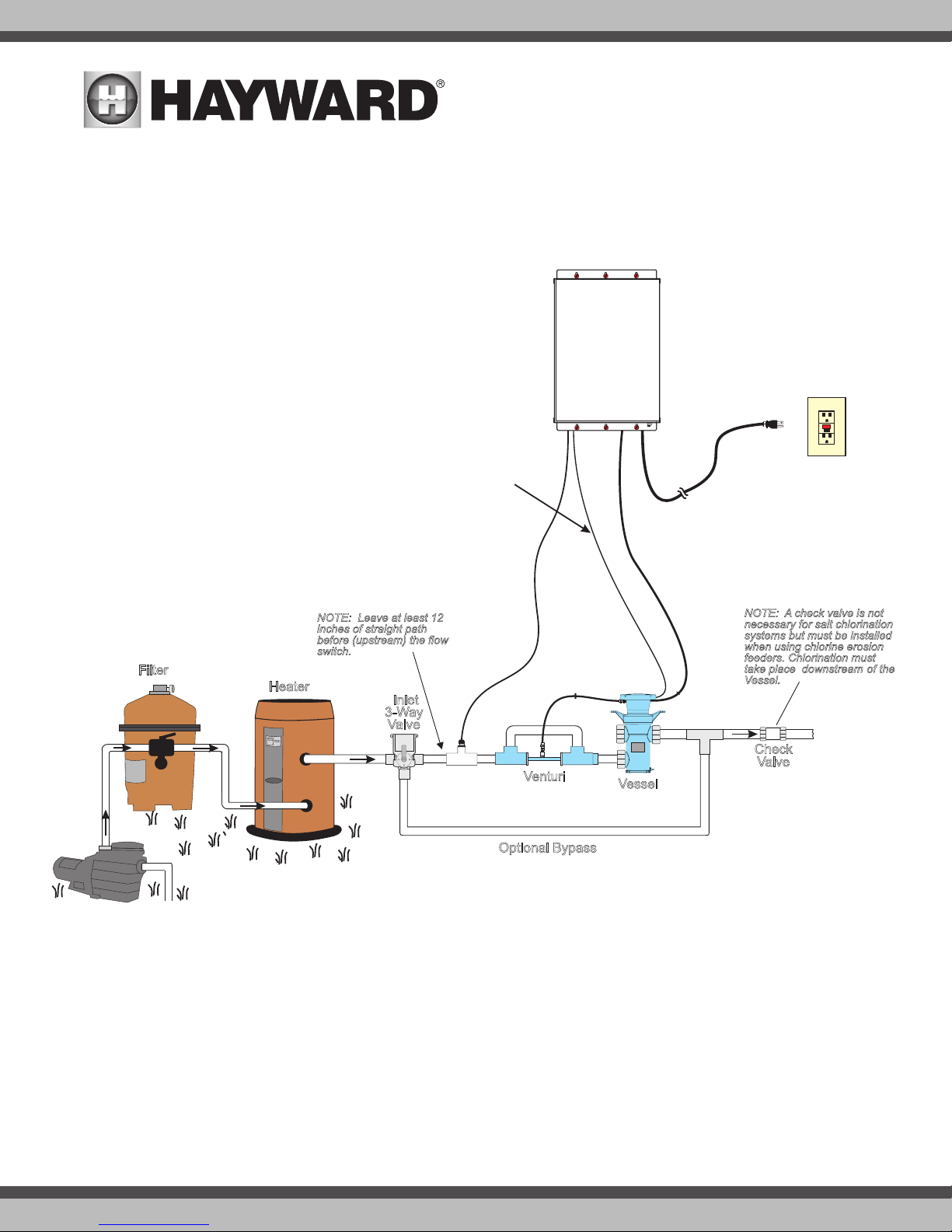
POOL
3ft
venturi
tube
NOTE: Leave at least 12
inches of straight path
before (upstream) the flow
switch.
Cell
Vessel
FROM
POOL
TO
POOL
Filter
Heater
GFCI
Outlet
15 ft
ballast
cable
interlock
cable
flow
switch
cable
6 ft
9 ft
9 ft
120
VAC
Check
Valve
Bypass
NOTE: A check valve is not
necessary for salt chlorination
systems but must be installed
when using chlorine erosion
feeders. Chlorination must take
place “downstream of the Cell
Vessel.
Inlet
3-Way
Valve
Installation
Before starting your installation, you MUST read this manual in its entirety in order to install your unit in a safe manner. Note that a few moments spent becoming
familiar with the HydroRite unit and its installation may save a great deal of time (and expense) later. If you have any questions that are unanswered when you
have completed the reading of this manual, contact your supplier or Hayward.
Overview
Filter
NOTE: In-line Chemical feeders and chlorinators should be
plumbed AFTER the HydroRite
system
Heater
Inlet
3-Way
Valve
interlock
cable
9ft
15 ft
flow
switch
cable
Venturi
Vessel
9ft
ballast
cable
6ft
NOTE: A check valve is not
necessary for salt chlorination
systems but must be installed
when using chlorine erosion
feeders. Chlorination must
take place downstream of the
Vessel.
Check
Valve
GFCI
Outlet
120
VAC
TO
POOL
Filter
Pump
FROM
Optional Bypass
Determine a suitable location
Installation of HydroRite system requires mounting the controller and vessel, plumbing the vessel, venturi and flow switch (on the return side of the filter pump),
and finally, connecting the required cables. Remove power to the pool filter pump before starting this installation. Installation must be performed in accordance
with local and NEC code.
The HydroRite vessel must be mounted at least 10 ft. from the pool. The controller must be mounted a minimum of 6 ft. horizontal distance (or more, if local
codes require) from the pool and has a 6 ft. power cord that must be connected to a GFCI protected circuit. Refer to the diagram above for lengths of other cords
and the venturi tube. Note that the vessel and flow switch will be plumbed into the return plumbing after the heater and all other equipment with the exception
of chemical feeders and chlorination systems.
3
USE ONLY HAYWARD GENUINE REPLACEMENT PARTS
Cell
Vessel
FROM
POOL
Filter
Heater
Filter
Pump
15 ft
ballast
cable
interlock
cable
flow
switch
cable
6 ft
9 ft
9 ft
Check
Valve
Bypass
NOTE: A check valve is not
necessary for salt chlorination
systems but must be installed
when using chlorine erosion
feeders. Chlorination must take
place “downstream of the Cell
Vessel.
Inlet
3-Way
Valve
Mounting the Controller
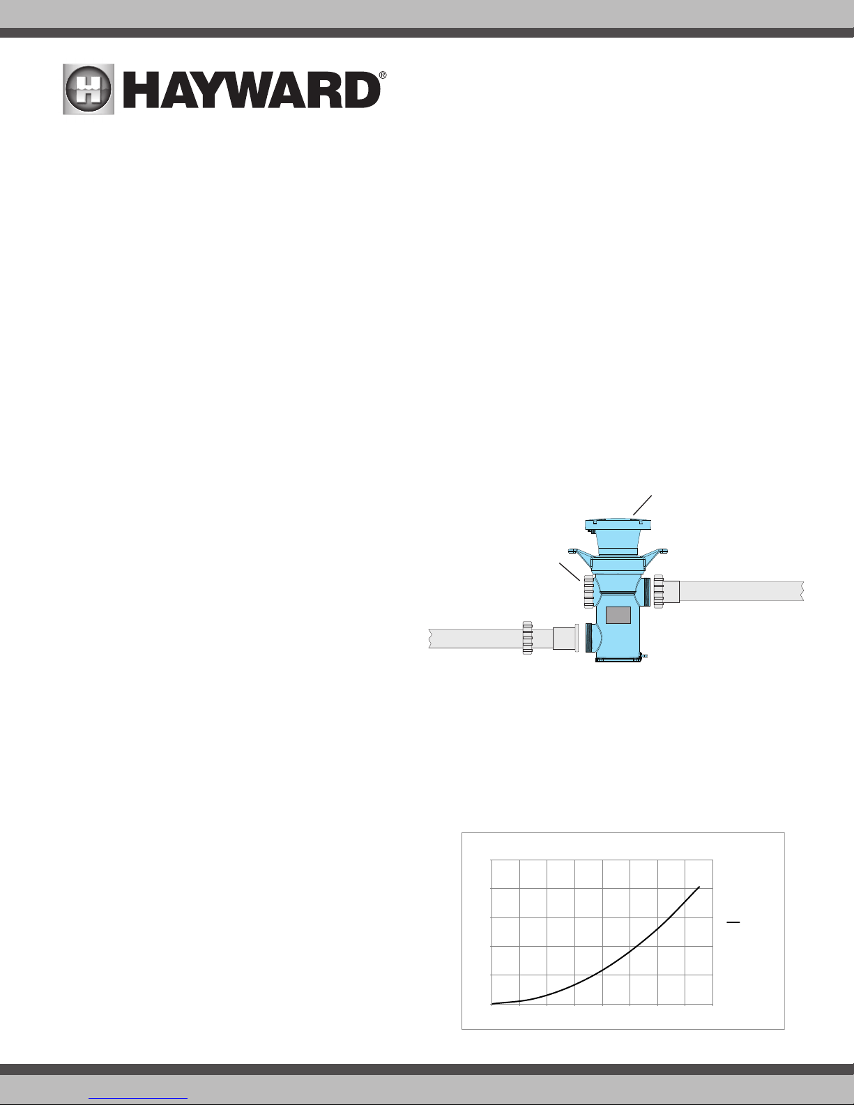
0
5
10
15
20
25
0 10 20 30 40 50 60 70 80
Head Loss (Feet of Water)
Flow Rate (GPM)
HydroRite Head Loss
HYR2CSUV-O3
Inlet Pipe
Union
Tail
Union
Nut
Do not
remove
Outlet Pipe
Vessel
Cap
The controller is designed to mount vertically on a flat surface with the cables facing downward. Because the enclosure also acts as a heat sink (disperses heat
from inside the box), it is important not to block the four sides of the controller. Do not mount the controller inside a panel or tightly enclosed area. If the supply
or a lamp cord is damaged, it must be replaced by the manufacturer, its service agent or similarly qualified persons in order to avoid a hazard.
After ensuring that the controller’s cables can reach their destinations, mount the controller to the intended surface using proper mounting hardware given the
size and weight of the unit. The controller’s mounting brackets require a total of 6 mounting bolts to fasten the controller to the mounting surface.
Plumbing the HydroRite System
Although not required, Hayward recommends that the HydroRite system be plumbed in a dedicated loop that can be bypassed as shown on page 3. A three-way
valve and actuator are supplied for this purpose. If plumbing a bypass, a tee fitting will be required. A bypass will aid in servicing and maintaining the HydroRite.
Note that the increased head of the HydroRite system may affect the performance of water features installed in the pool’s system. A bypass will allow you to
divert water directly to water features although be aware that the HydroRite will not sanitize under these circumstances.
Installation of 3-way valves on BOTH the inlet and outlet lines attached to the vessel plumbing is mandatory if an automatic vessel cleaner is used, or if the
vessel and associated plumbing is located below the waterline. Failure to use valves where any portion of the device is below the waterline will not allow the
device to be properly drained which could lead to cracking of the unit if any retained water freezes.
Securing the Vessel
When the vessel installation location has been determined, it should be secured to a concrete or wood base. Four mounting holes are located in the mounting
base of the unit that accommodates ¼ inch diameter bolts to mount the HydroRite unit in place. FAILURE TO PROPERLY SECURE THE UNIT MAY CAUSE NOISE
DUE TO VIBRATION CAUSED BY WATER PASSING THROUGH THE WET CHAMBER. Secure the vessel using bolts and anchors (not supplied) where necessary
and appropriate for your installation.
Plumbing the Vessel
The HydroRite vessel comes with union nuts and tails pre-assembled on
the housing. Remove the Inlet and Outlet nuts and note the orientation of
the orange gaskets when removing union tails. These will need to be put
back together after gluing the union tails to the pool piping.
After cutting pipe to length, slide one union nut onto the cut pipe and
glue the gray tail piece to the pipe end. Repeat for the other pipe. Thread
the union nuts onto the vessel and handtighten both unions. DO NOT
OVERTIGHTEN. OVERTIGHTENING WILL BREAK THE UNION NUTS. To avoid
stress on the connections at the vessel, piping should be supported and
should not rest solely upon the unions.
Plumbing the Flow Switch
The flow switch is a safety device that ensures that the HydroRite is only operating when there is water passing through the vessel. The flow switch must be
plumbed in the same section of plumbing as the vessel. Failure to properly install the flow switch can result in damage to the pool’s equipment.
IMPORTANT: There must be at least a 12” (30cm) straight pipe run before (upstream) the flow switch.
IMPORTANT: To ensure proper operation, verify that the arrow on the flow switch points in the direction of water flow.
Head Loss
Refer to the adjacent table below for Head Loss information.
Venturi
The venturi assembly is pre-assembled and ready to be plumbed. A 3 ft
hose connection is made from the venturi to the ozone manifold at the vessel
as shown in the diagram on page 3. More information about the venturi tube
and connection can be found on page 5.
Chlorination Systems
Care must be taken to prevent exposure of the vessel to high concentrations of chlorine. All in-line chlorine systems must be installed AFTER (downstream) the vessel.
USE ONLY HAYWARD GENUINE REPLACEMENT PARTS
HYD-UVO
4
 Loading...