

Hayward HRCK2A, HRCK2B, HRCK2R, HRSN3A, HRCK2S Installation, Operation And Maintenance Instructions
...Page 1
INSTALLATION, OPERATION AND
MAINTENANCE INSTRUCTIONS
LCS Products Supplement
to HRSN2 through HRSN6 Series
Low Voltage and Single Phase Products
TO PREVENT POTENTIAL INJURY OR DAMAGE TO PROPERTY, READ THIS MANUAL CAREFULLY AND COMPLETELY.
Back to TOC
Hayward Flow Control
1-888-HAY-INDL (1-888-429-4635)
USE ONLY HAYWARD GENUINE REPLACEMENT PARTS
www.haywardowcontrol.com
HRSLCSSPLMNTIOM Rev A
Page 1 of 42
Page 2
IMPORTANT SAFETY INSTRUCTIONS
Basic safety precautions should always be followed, including the following: Failure to follow instructions
can cause severe injury and/or death.
This is the safety-alert symbol. When you see this symbol on your equipment or in this manual, look
for one of the following signal words and be alert to the potential for personal injury.
WARNING warns about hazards that could cause serious personal injury, death or major property
damage and if ignored presents a potential hazard.
CAUTION warns about hazards that will or can cause minor or moderate personal injury and/or
property damage and if ignored presents a potential hazard. It can also make consumers aware of
actions that are unpredictable and unsafe.
Notice:
A notice indicates special instructions that are important but not related to hazards.
WARNING - Read and follow all instructions in this IOM manual and on the equipment. Failure
to follow instructions can cause severe injury and/or death.
WARNING – Risk of Electric Shock. All electrical wiring MUST be in conformance with applicable
local codes, regulations, and the National Electric Code (NEC). Hazardous voltage can shock, burn,
and cause death or serious property damage. To reduce the risk of electric shock, do NOT use an
extension cord to connect unit to electric supply. Provide a properly located electrical receptacle.
Before working on any electrical equipment, turn off power supply to the equipment.
WARNING – To reduce the risk of electric shock replace damaged wiring immediately.
WARNING – Ground all electrical equipment before connecting to electrical power supply.
Failure to ground all electrical equipment can cause serious or fatal electrical shock hazard.
WARNING – Do NOT ground to a gas supply line.
WARNING – To avoid dangerous or fatal electrical shock, turn OFF power to all electrical
equipment before working on electrical connections.
WARNING – Failure to bond all electrical equipment to system structure will increase risk for
electrocution and could result in injury or death. To reduce the risk of electric shock, see installation
instructions and consult a professional electrician on how to bond all electrical equipment. Also,
contact a licensed electrician for information on local electrical codes for bonding requirements.
CAUTION – Potential pinch point. Equipment connected to or driven by this device may start
unexpectedly and may cause personal injury or entrapment in linkage systems.
Back to TOC
Hayward Flow Control
1-888-HAY-INDL (1-888-429-4635)
USE ONLY HAYWARD GENUINE REPLACEMENT PARTS
www.haywardowcontrol.com
HRSLCSSPLMNTIOM Rev A
Page 2 of 42
Page 3

TABLE OF CONTENTS
HR2~6 LVHV LCS Series
Important Safety Instructions .....................2
Table of Contents ...............................3
LCS Supplement to HRS Series Actuators ..........4
Conventions Used in this Manual ..................5
Theory of Operation .............................6
HRCK, HRCP On/Off Control ..................6
HRCK, HRCP Proportional Control .............. 7
HRCL, HRCD On/Off Control ..................8
HRCL, HRCD Proportional Control ..............9
CK Series LCS Operation .......................10
CP Series LCS Operation .......................11
CL Series LCS Operation .......................12
CD Series LCS Operation .......................13
LCS Calibration and Commissioning ..............14
HRCK On/Off Control .......................14
HRCK Proportional Control ................... 16
HRCP On/Off Control .......................18
HRCP Proportional Control ................... 20
HRCL On/Off Control .......................22
HRCL Proportional Control ................... 24
HRCD On/Off Control .......................26
HRCD Proportional Control ...................28
Notes ....................................31
Mechanical Data ..............................32
HRCK2A~2S Exploded View ..................32
HRCK2A~2S Dimensional Data ..............33
HRCK, HRCP 3A~4F Exploded View ...........34
HRCK, HRCP 3A~4F Dimensional Data ........35
HRCK, HRCP 5A~6A Exploded View ...........36
HRCK, HRCP 5A~6A Dimensional Data ........37
HRCL, HRCD 3A~4F Exploded View ...........38
HRCL, HRCD 3A~4F Dimensional Data ........39
HRCL, HRCD 5A~6A Exploded View ...........40
HRCL, HRCD 5A~6A Dimensional Data ........41
Notice: HRCK, HRCP, HRCL & HRCD Series actuators are fully assembled, calibrated and tested prior to
leaving our factory. In most cases, after you have mounted the actuator to your device, you should be able to
operate the actuator from fully CLOSED (CW) to fully OPEN (CCW) and back again, and nd that no adjustments
are needed. The assembly can be put into service immediately.
If, however, it should be necessary to make adjustments to the end-of-travel positions to overcome any device
related issues (i.e. valve shaft incorrectly timed to the drive stem), the procedures outlined in the Installation,
Operation and Maintenance Instructions (IOM) for each unit should be followed to put the assembly into
service. Note that there is a maximum adjustment range of +/- 3° at each end of travel.
CAUTION – For any 3 Phase products (i.e. HRCK4AR8), refer to the IOM for the respective 3 Phase unit.
These instructions are specic to low voltage and single phase products only.
Back to TOC
Hayward Flow Control
1-888-HAY-INDL (1-888-429-4635)
USE ONLY HAYWARD GENUINE REPLACEMENT PARTS
www.haywardowcontrol.com
HRSLCSSPLMNTIOM Rev A
Page 3 of 42
Page 4
LCS SUPPLEMENT TO HRS SERIES ACTUATORS
Local Control Stations (LCS) provide a means to select Local or Remote control of a valve or damper actuator.
There are four different types of LCS offered on the HRS series actuators. Each of these four types provide unique
capabilities and human-machine interface.
This supplemental Guide is to be utilized in conjunction with the
actuator IOM. This document differs from the actuator IOM.
This guide will provide necessary wiring diagrams which will differ
from those provided in the actuator IOM itself. You MUST utilize the
wiring diagrams provided in this supplement.
Dimensional Data will differ from that provided in the actuator IOM.
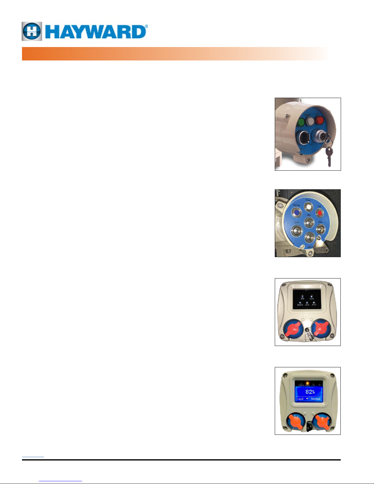
Type CK – Key/Knob type. This is an IP65 type round enclosure that is integral to
the actuator housing. It employs a key switch for the Mode select, a knob switch
for Move commands, and three LED indicators indicating Power, Open and Closed
positions. This version is available on HRSN2 thru HRSN6 Series 24v, 120v & 230v On/
Off actuators.
Type CP – Push Button type. This is an IP67 type round enclosure that is integral to
the actuator housing. This model utilizes push buttons (press-press) to select Remote/
Local Mode, Open/Stop/Close Mode, and LED indicators to show Power, Running
Open and Fully Open, Running Closed and Fully Closed positions. This version is
available on HRSN3 thru HRSN6 Series 24v, 120v & 230v On/Off and Proportional
Control actuators.
Type CK
Type CL – LED type. This is an IP67 rectangular enclosure integral with the actuator
housing. This model has non-intrusive magnetic type knob switches for Mode and
Position control. This version also employs an LED panel mounted behind glass with
indicators for Open, Close, Remote, Local and Fault. This version is available on HRSN3
thru HRSN6 Series 24v, 120v & 230v On/Off and Proportional Control actuators.
Type CD – LCD type. This is an IP67 rectangular enclosure integral with the actuator
housing. This model has non-intrusive magnetic type knob switches for Mode and
Position control. This version utilizes a monochrome (blue) LCD panel that provides
graphic information regarding the status of the actuator. Its main feature is a large
% display in the center of the screen which shows the position of the actuator as a
function of % of full OPEN. The numeric display ashes when the actuator is moving.
There are UP and DN arrows showing direction of travel.
The lower line of text in the display shows mode of operation, normal status, fault
status, and torque switch trips in their respective directions. There are also LED
indicators above the screen that show Local, Remote, Open and Closed functions.
This version is available on HRSN3 thru HRSN6 Series 24v, 120v & 230v On/Off and
Proportional Control actuators
Type CP
Type CL
Back to TOC
Hayward Flow Control
1-888-HAY-INDL (1-888-429-4635)
USE ONLY HAYWARD GENUINE REPLACEMENT PARTS
www.haywardowcontrol.com
Type CD
HRSLCSSPLMNTIOM Rev A
Page 4 of 42
Page 5

CONVENTIONS USED IN THIS MANUAL
Below are Terms and Denitions used throughout this manual.
1. XTS/TS product manufactured without/with Torque Switches.
2. LCS product manufactured with attached Local Control Station.
Depending on the options required you can efciently select the level of actuator and wiring diagram you require.
ACTUATOR OPTIONS
Control Voltage Actuator Range* Torque Switches** Local Control Wiring Diagram Page
On/Off 24VDC/VAC HRCK2A~6A XTS/TS LCS CK
On/Off 120/230VAC HRCK2A~6A XTS/TS LCS CK
On/Off 24VDC/VAC HRCP3A~6A XTS/TS LCS CP
On/Off 120/230VAC HRCP3A~6A XTS/TS LCS CP
Mod 24VDC/VAC HRCK2A~6A XTS/TS LCS CK
Mod 120/230VAC HRCK2A~6A XTS/TS LCS CK
Mod 24VDC/VAC HRCP3A~6A XTS/TS LCS CP
Mod 120/230VAC HRCP3A~6A XTS/TS LCS CP
On/Off 24VDC/VAC HRCL3A~6A XTS/TS LCS CL
On/Off 120/230VAC HRCL3A~6A XTS/TS LCS CL 8
On/Off 24VDC/VAC HRCD3A~6A XTS/TS LCS CD 8
On/Off 120/230VAC HRCD3A~6A XTS/TS LCS CD 8
Mod 24VDC/VAC HRCL3A~6A XTS/TS LCS CL 9
Mod 120/230VAC HRCL3A~6A XTS/TS LCS CL 9
Mod 24VDC/VAC HRCD3A~6A XTS/TS LCS CD 9
Mod 120/230VAC HRCD3A~6A XTS/TS LCS CD
6
6
6
6
7
7
7
7
8
9
* The only LCS available in the HRSN2A~2S range is the LCS CK.
** Some frame sizes are available only with TS (no XTS option).
Back to TOC
Hayward Flow Control
1-888-HAY-INDL (1-888-429-4635)
USE ONLY HAYWARD GENUINE REPLACEMENT PARTS
www.haywardowcontrol.com
HRSLCSSPLMNTIOM Rev A
Page 5 of 42
Page 6

HRCK, HRCP 2A~6A
24V~230V On/Off Control
LCS, XTS/TS
THEORY OF OPERATION
HRCK and HRCP advanced stand-alone actuators are designed to be installed in new contruction sites or existing
sites where there are NO existing local control capabilities. These single phase and low voltage actuators have
several versions that continue to add more features and options than the standard actuator range.
Moreover, these units incorporate a Local Control Station (LCS) to facilitate operating the actuator. Having this
feature allows operation of the actuator WITHOUT having an existing PLC or BAS based analog controller while also
providing operability with existing external controls.
Inside the actuator/LCS package, you will nd:
1. Integral Local Control Device. This series is designed to operate in Local mode (control knobs or buttons located
on the face of the LCS, which is an integral part of the actuator) or in Remote mode, which utilizes commands from
a PLC, BAS or other volt-free contact (dry contact) automation device.
A. While in Remote mode, the Remote
devices must have volt-free contacts
(dry contacts) which will switch the
actuator’s internal 24vac power
supply to generate commands to
drive CW or CCW.
B. While in Local mode, the actuator
responds to the position of the
controls located on the face of the
integral LCS.
C. The Mode switch (CK Series) is operated
by a removable key which, when
removed, will prevent unauthorized
changes in the operating mode
(Local, Off or Remote).
D. The Mode button (CP Series) is
protected by a lockable cover
plate which, when locked, will
prevent unauthorized changes in
the operating mode (Local, Off or
Remote).
Apply no external power
Back to TOC
Hayward Flow Control
1-888-HAY-INDL (1-888-429-4635)
USE ONLY HAYWARD GENUINE REPLACEMENT PARTS
www.haywardowcontrol.com
WD75TS
HRSLCSSPLMNTIOM Rev A
Page 6 of 42
Page 7
HRCK, HRCP 3A~6A
24V~230V Proportional Control
LCS, TS
THEORY OF OPERATION
HRCK and HRCP advanced stand-alone actuators are designed to be installed in new contruction sites or existing
sites where there are NO existing local control capabilities. These single phase and low voltage actuators have
several versions that continue to add more features and options than the standard actuator range.
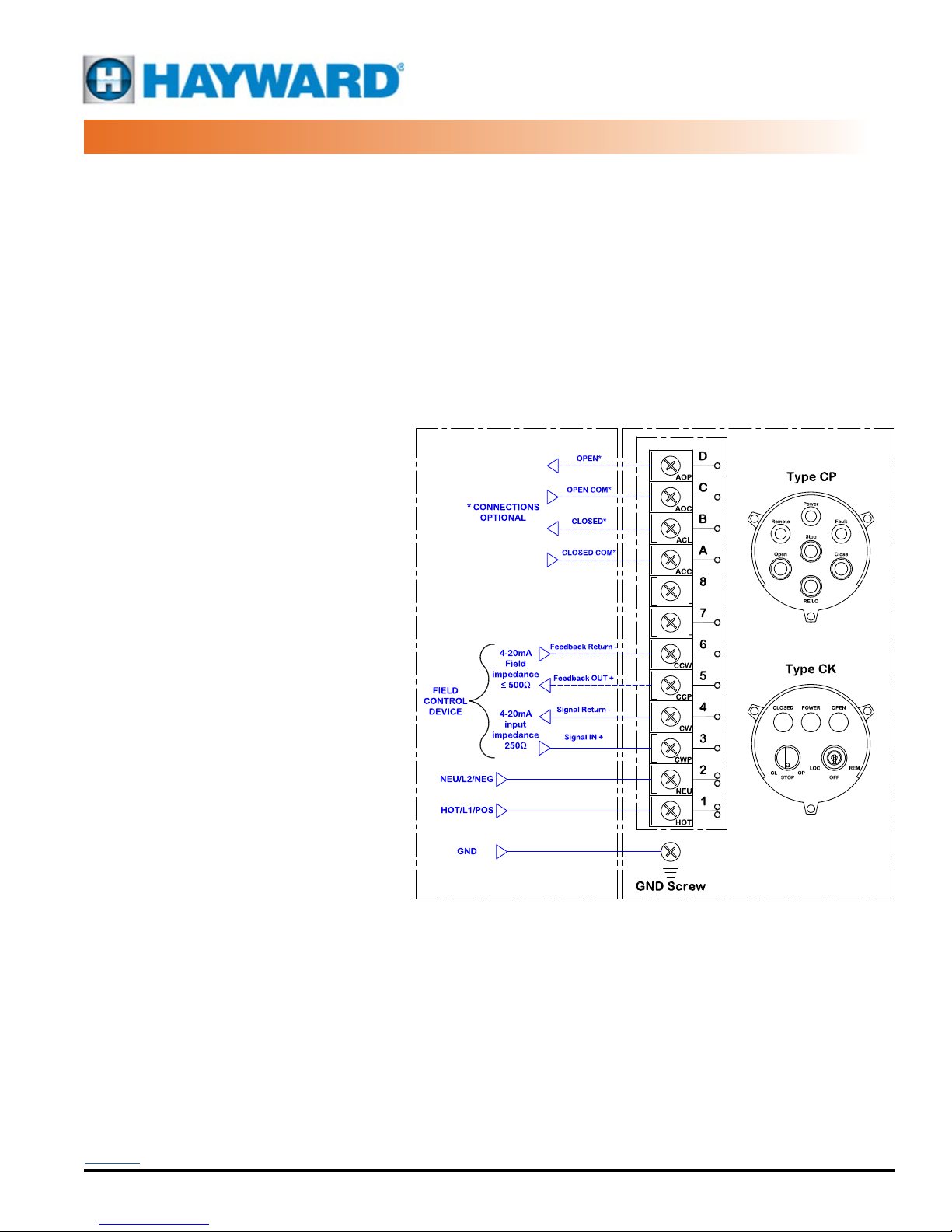
These units accept analog control signals (4-20mA or 2-10vdc) and process these incoming signals to position the
actuator as a function of the incoming signal. Additionally, these units generate an analog feedback signal proportional
to the position of the actuator and not directly related to the incoming signal. This feedback signal is designed to be
used by automation devices or displays external to the actuator.
Moreover, these units incorporate a Local Control Station (LCS) to facilitate operating the actuator locally. Having this
feature allows operation of the actuator WITHOUT having an existing PLC or BAS based analog controller while also
providing operability with existing external controls.
Inside the actuator/LCS package, you will nd:
1. Integral Local Control Device. This
series is designed to operate in Local
mode (control knobs located on the
face of the LCS which is an integral
part of the actuator) or in Remote
mode, which utilizes commands from
a PLC, BAS or other volt-free contact
(dry contact) automation device.
A. While in Local mode, the actuator
responds to the position of the
controls located on the face of the
integral LCS.
B. The Mode switch is operated by
a removable key which, when
removed, will prevent unauthorized
changes in the operating mode
(Local, Off or Remote).
2. Proportional Controller. When the unit is
in Remote Mode, this analog processing
Printed Circuit Board (PCB) accepts
4-20mA or 2-10vdc from the eld and
positions the actuator accordingly,
utilizing the internal reversing motor
starter. A 4-20mA or 2-10vdc feedback
signal is internally generated to provide
remote reading of the position of the
actuator.
Back to TOC
Hayward Flow Control
1-888-HAY-INDL (1-888-429-4635)
USE ONLY HAYWARD GENUINE REPLACEMENT PARTS
www.haywardowcontrol.com
WD76TS
HRSLCSSPLMNTIOM Rev A
Page 7 of 42
Page 8
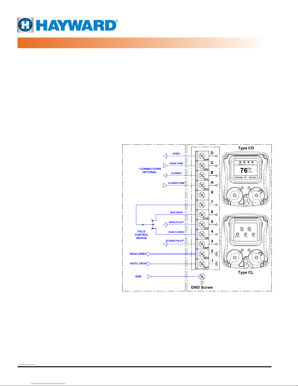
HRCL, HRCD 3A~6A
24V~230V On/Off Control
LCS, XTS/TS
THEORY OF OPERATION
HRCL and HRCD advanced stand-alone actuators are designed to be installed in new contruction sites or existing
sites where there are NO existing local control capabilities. These single phase and low voltage proportional control
actuators have several versions that continue to add more features and options than the standard actuator range.
These actuators generate a 24V control output that is connected to a remote PLC or BAS to control the actuator. This
24v output also serves as a status of the power connections and actuator operability. Any internal faults will disable
the 24v control output. Moreover, these units incorporate a Local Control Station (LCS) to facilitate operating the
actuator locally. Having this feature allows operation of the actuator WITHOUT having an existing PLC or BAS based
analog controller while also providing operability with existing external controls.
Inside the actuator/LCS package, you will nd:
1. Integral Local Control Device. This series is designed to operate in Local mode (control knobs located on the face
of the LCS which is an integral part of the actuator) or in Remote mode, which utilizes commands from a PLC, BAS
or other volt-free contact (dry contact) automation device.
A. While in Local mode, the actuator
responds to the position of the
controls located on the face of the
integral LCS.
B. The Mode switch (CL and CD
Series) employs a padlockable
lever that locks the Mode switch
in any of its three positions,
preventing unauthorized changes
in the operating mode (Local, Off or
Remote).
Apply no external power
Back to TOC
Hayward Flow Control
1-888-HAY-INDL (1-888-429-4635)
USE ONLY HAYWARD GENUINE REPLACEMENT PARTS
www.haywardowcontrol.com
WD135TS
WD165TS
HRSLCSSPLMNTIOM Rev A
Page 8 of 42
Page 9

HRCL, HRCD 3A~6A
24V~230V Proportional Control
LCS, TS
THEORY OF OPERATION
HRCL and HRCD advanced stand-alone actuators are designed to be installed in new contruction sites or existing
sites where there are NO existing local control capabilities. These single phase and low voltage proportional control
actuators have several versions that continue to add more features and options than the standard actuator range.
These units accept analog control signals (4-20mA or 2-10vdc) and process these incoming signals to position the
actuator as a function of the incoming signal. Additionally, these units generate an analog feedback signal proportional
to the position of the actuator and not directly related to the incoming signal. This feedback signal is designed to be
used by automation devices or displays external to the actuator.
Moreover, these units incorporate a Local Control Station (LCS) to facilitate operating the actuator locally. Having this
feature allows operation of the actuator WITHOUT having an existing PLC or BAS based analog controller while also
providing operability with existing external controls.
Inside the actuator/LCS package, you will
nd:
1. Integral Local Control Device. This
series is designed to operate in Local
mode (control knobs located on the face
of the LCS which is an integral part of
the actuator) or in Remote mode, which
utilizes commands from a PLC, BAS
or other volt-free contact (dry contact)
automation device.
A. While in Local mode, the actuator
responds to the position of the
controls located on the face of the
integral LCS.
B. The Mode switch employs a
padlockable lever that locks the
Mode switch in any of its three
positions, preventing unauthorized
changes in the operating mode
(Local, Off or Remote).
2. Proportional Controller. When the unit is
in Remote Mode, this analog processing
Printed Circuit Board (PCB) accepts
4-20mA or 2-10vdc from the eld and
positions the actuator accordingly, utilizing
the internal reversing motor starter. A
4-20mA or 2-10vdc feedback signal is
internally generated to provide remote
reading of the position of the actuator.
Back to TOC
Hayward Flow Control
1-888-HAY-INDL (1-888-429-4635)
USE ONLY HAYWARD GENUINE REPLACEMENT PARTS
www.haywardowcontrol.com
WD136TS
WD166TS
HRSLCSSPLMNTIOM Rev A
Page 9 of 42
Page 10
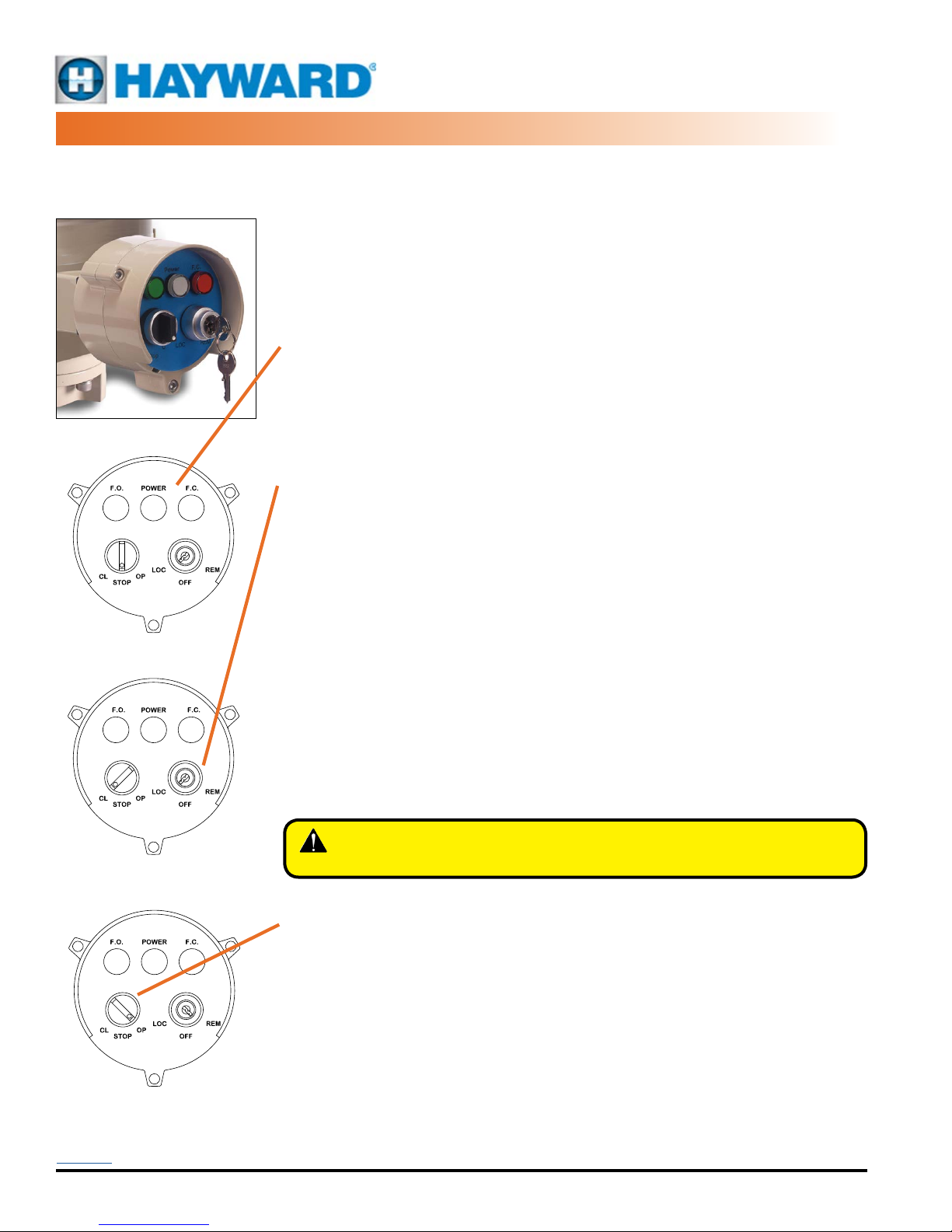
CK SERIES LCS OPERATION
ROUND LCS, KEYED
Operating the
Local Control Station
Panel Indicators
This round NEMA 4X/IP65 enclosure houses two rotary control knobs that provide the user with
the ability to operate the actuator in a normal (REMOTE) mode where the actuator responds
to control signals from a building automation system or a PLC or other control device (by
others). Or the user can elect to operate the actuator in LOCAL mode where one can control
the positioning of the actuator while standing AT the device. This allows opening and closing
the actuator (valve) to test for operation, perform maintenance or other function without relying
on radio communication to command the automation system to position the actuator.
A Key is provided for lockout and secured access to the MODE control switch of the
actuator. With the key removed (from any of the three positions), the MODE switch cannot
be changed.
The Position Indicators (top).
POWER (POWER indicator, all actuators): The Power LED is illuminated whenever power is
present at the unit, regardless of MODE position.
The panel also contains two colored LED indicators to provide visual indication of the position
and status of the actuator. The green Fully Open LED corresponds to the OPEN actuator
position. The red Fully Closed LED corresponds to the CLOSED actuator position. Both remain
steady ON when their respective end of travel is reached.
The MODE switch (right hand side) has three positions.
• REM (REMOTE, On/Off actuators): sets the actuator to respond to eld generated
control signals. In this mode the POSITION KNOB has NO affect on the positioning
of the actuator. All actuator movement is controlled by the external signal device.
The manual handwheel may be used to reposition the actuator while in this mode;
however, if an active external signal is present, the actuator WILL reposition as a
function of that control signal. The indicators are active in this mode.
• REM (REMOTE, Proportional Control actuators): The actuator follows the incoming
4-20mA(2-10vdc) control signal, and generates a 4-20mA(2-10vdc) feedback signal
OUT which corresponds to the position of the actuator.
• LOC (LOCAL, On/Off actuators): sets the actuator to respond to the POSITION KNOB.
The indicators are active in this mode.
• LOC (LOCAL, Proportional Control actuators): The actuator responds to the function
of the POSITION knob AND generates a 4-20mA(2-10vdc) feedback signal OUT
which corresponds to the position of the actuator.
• OFF (all models) In the OFF position, electronic movement of the actuator is disabled.
The actuator will NOT respond to any incoming remote or local signals. The actuator MAY
be operated manually using the handwheel and the unit will STAY in its desired position.
Panel shown in the
Local Mode
The POSITION switch (left hand side) has three positions.
When power is present in the unit, the mode switch is operational.
• STOP (center position) removes any ability to reposition the actuator electrically.
• STOP with Proportional Control actuators: The actuator generates a 4-20mA (2-10vdc)
• OP (OPEN) set the POSITION switch to OP to drive the actuator to the full CCW position.
• CL (CLOSE) set the POSITION switch to CL to drive the actuator to the full CW position.
• The position switch can be used to “bump” or “jog” the actuator incrementally in
Panel shown in the
Remote Mode driving OPEN
Back to TOC
Hayward Flow Control
1-888-HAY-INDL (1-888-429-4635)
WARNING – Being in the OFF mode does NOT serve as a power disconnect.
Live voltage will still be present inside the actuator.
feedback signal OUT which corresponds to the position of the actuator.
either direction as well.
USE ONLY HAYWARD GENUINE REPLACEMENT PARTS
www.haywardowcontrol.com
HRSLCSSPLMNTIOM Rev A
Page 10 of 42
Page 11
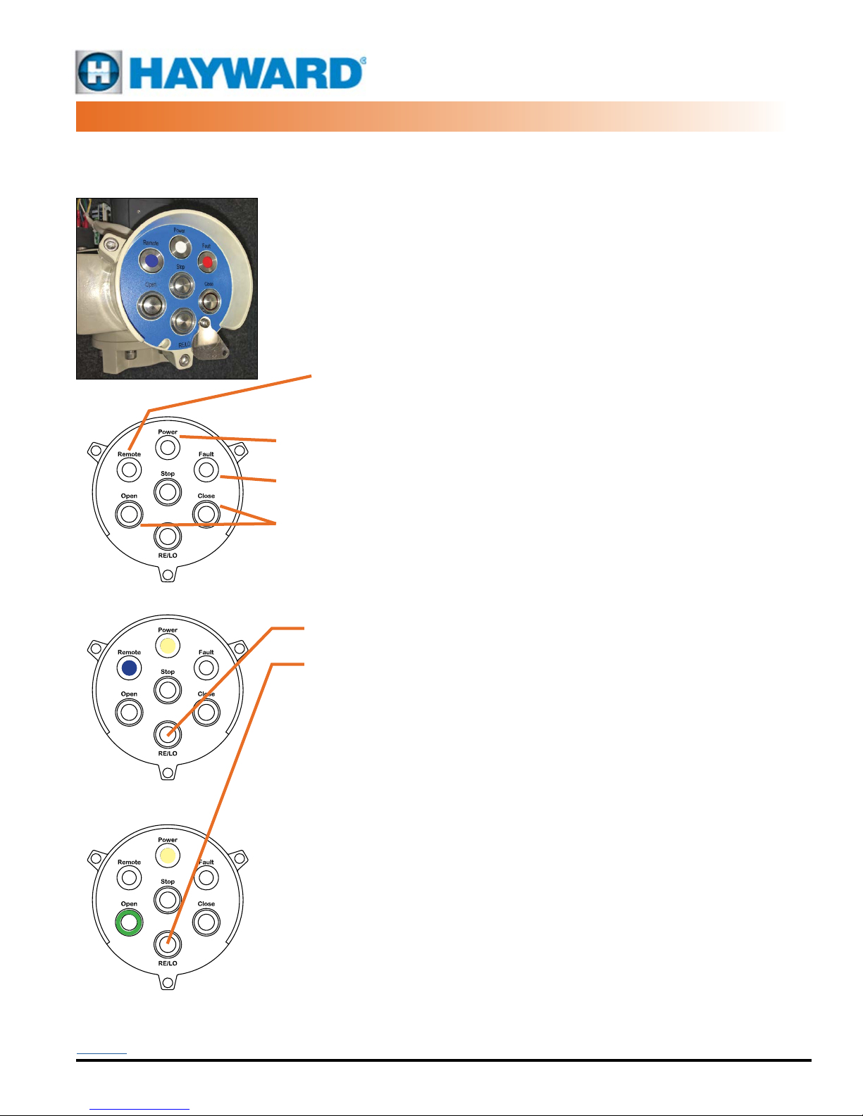
CP SERIES LCS OPERATION
ROUND LCS, PUSHBUTTON
Operating the
Local Control Station
This round NEMA 4X/IP67 enclosure houses four pushbutton control switches that provide the
user with the ability to operate the actuator in a normal (REMOTE) mode where the actuator
responds to control signals from a building automation system or a PLC or other control device
(by others). Or the user can elect to operate the actuator in LOCAL mode where one can
control the positioning of the actuator while standing AT the device. This allows opening and
closing the actuator (valve) to test for operation, perform maintenance or other function without
relying on radio communication to command the automation system to position the actuator.
The panel houses three status LED’s that indicate Power, Remote operation, and a Fault
indicator. There are also four push button switches (non-latching, push/push) two of which
also have ring surround LEDs providing the operational status of the actuator. Whenever power
is present at the unit, regardless of MODE position, the Power LED is illuminated.
REMOTE (REMOTE MODE indicator, all actuators):
• The RE/LO mode switches from Local to Remote and back with each
successive press of the push button (see below).
• When the unit is in Remote mode, the Blue Remote LED will be illuminated.
• When the unit is in Local mode, the Remote LED will be OFF.
POWER (POWER indicator, all actuators): The Power LED is illuminated whenever power is
present at the unit, regardless of MODE position.
FAULT (FAULT indicator, all actuators): The Fault LED is illuminated whenever there is a fault
detected in the actuator.
OPEN/CLOSE (OPEN and CLOSE indicators, all actuators): Regardless of the Mode of
operation (other than powered OFF), the Open and Close push buttons have internal LED
rings which ash Red (Closing) or Green (Opening). When end of travel is reached, the LED
indicators remain constant ON.
Panel shown with NO POWER
Panel shown in the
Remote Mode
Panel shown in the
Local Mode, actuator fully OPEN
RE/LO (REMOTE/LOCAL, all actuators): When the RE/LO push button is pressed, the mode
switches from Local to Remote and back with each successive press of the push button.
• REMOTE: When the unit is in Remote mode, the three Move push
buttons are disabled and have no effect on the operation of the actuator.
• LOCAL: When the unit is in Local mode (Blue LED OFF), the three Move
push buttons are enabled and one can control the position of the actuator
using the push buttons.
OPEN: Pressing the Open push button drives the actuator CCW until it reaches the end of
travel determined by the internal CCW travel cam settings.When pressed (momentary switch),
the unit will start and continue to drive until it reaches its full CCW position UNLESS the Stop
push button is pressed. This will arrest the CCW travel of the actuator and it will stay in its
current position UNLESS the manual handwheel is utilized.
CLOSE: Pressing the Close push button drives the actuator CW until it reaches its CW end of
travel limit switch.
STOP: Pressing the Stop push button stops the actuator in position.
Using the manual handwheel. In Remote mode with an active control signal present,
repositioning the actuator with the handwheel will result in the unit driving to maintain the
control signal command. i.e. if in Remote mode with a drive CW active control signal, if the
handwheel is utilized to reposition the actuator to mid-stroke, the motor will immediately drive
the actuator to its full CW position. While in Local Mode, the manual handwheel can be used
to reposition the actuator to any desired position AFTER the unit has reached its intended end
of travel position and the associated ring LED is illuminated.
This Control system employs a pad-lockable security plate that can be positioned over the
MODE push button and locked in place. This prevents changing the mode of operation. The lock
plate must be unlocked and swung out of the way to gain access to the mode switch function.
Back to TOC
Hayward Flow Control
1-888-HAY-INDL (1-888-429-4635)
USE ONLY HAYWARD GENUINE REPLACEMENT PARTS
www.haywardowcontrol.com
HRSLCSSPLMNTIOM Rev A
Page 11 of 42
Page 12

CL SERIES LCS OPERATION
RECTANGULAR LCS, LED
Operating the
Local Control Station
Panel shown in the STOP Mode
Panel shown in the Remote Mode
Panel shown in the Local Mode
driving CLOSED
Panel shown in the Local Mode
driving OPEN
There is a padlockable lever that engages with the MODE
knob to lock the operation of the MODE switch in position.
It provides restricted access in any of the three positions.
Back to TOC
Hayward Flow Control
1-888-HAY-INDL (1-888-429-4635)
This rectangular NEMA 4X/IP67 (Optional IP68) enclosure houses two non-intrusive
(magnetic) rotary control knobs that provide the user with the ability to operate the
actuator in a normal (REMOTE) mode where the actuator responds to control signals
from a building automation system or a PLC or other control device (by others). Or
the user can elect to operate the actuator in LOCAL mode where one can control
the positioning of the actuator while standing AT the device. This allows opening
and closing the actuator (valve) to test for operation, perform maintenance or other
function without relying on radio communication to command the automation system
to position the actuator.
The panel also contains ve bright LED’s to provide visual indication of the position
and status of the actuator. OPEN (green) and CLOSE (red) ash when the actuator
is MOVING open (CCW) or closed (CW), and they remain steady ON when end of
travel is reached.
The MODE switch (right hand side) has three positions.
• STOP (STOP, On/Off actuators): STOP (center position) removes any ability
to reposition the actuatorelectrically. Power is still present in the unit, and
the OPEN and CLOSE LED indicators are operational. If the unit is fully
CLOSED (CW), then the REDLED will be steady ON. Due to its epicyclic
gear train, the manual handwheelCAN be used to position the actuator. The
actuator will remain in position lastdetermined by the use of the handwheel.
• STOP (STOP, Proportional Control actuators): The actuator generates
a4-20mA(2-10vdc) feedback signal OUT which corresponds to the position
of theactuator.
• REM (REMOTE, On/Off actuators): Sets the actuator to respond to eld
generated control signals. In this mode the POSITION KNOB (left side)
has NO affect on the positioning of the actuator. All actuator movement
is controlled by the external signal device.The manual handwheel may be
used to reposition the actuator while in this mode; however, if an active
external signal is present, the actuator WILLreposition as a function of that
control signal. The LED indicators are activein this mode.
• REM (REMOTE, Proportional Control actuators): The actuator follows
theincoming 4-20mA(2-10vdc) control signal, and generates a 4-20mA(2-10vdc)
feedback signal OUT which corresponds to the position of the actuator.
• LOC (LOCAL, On/Off actuators): Sets the actuator to respond to the
POSITION KNOB (see below).
• The LED indicators are active in this mode.
• All external eld signals are ignored and have no affect on the
positioning of theactuator.
• LOC (LOCAL, Proportional Control actuators): The actuator responds tothe
function of the POSITION knob (see below) AND generates a 4-20mA(210vdc)feedback signal OUT which corresponds to the position of the actuator.
The POSITION switch (left hand side) has three positions.
When in the LOC mode, the actuator has been set to respond to the POSITION
KNOB (left side).
• OPE (OPEN, all models): When the POSITION knob is set to OPE, the
actuator will drive to the full CCWposition.
• CLO (CLOSE, all models): When the POSITION knob is set to CLO, the
actuator will drive tothe full CW position.
• There is an unmarked HOLD position detente in theknob (see red dot at
left) that allows the actuator to maintain position at somepoint away from
full travel endstops. In this mode, the manual handwheelmay be used to
reposition the actuator and it will remain in position whilePOSITION knob
is in HOLD. The LED indicators are active in this mode. Allexternal eld
signals are ignored and have no affect on the positioning of theactuator.
USE ONLY HAYWARD GENUINE REPLACEMENT PARTS
www.haywardowcontrol.com
HRSLCSSPLMNTIOM Rev A
Page 12 of 42
Page 13

CD SERIES LCS OPERATION
RECTANGULAR LCS, LCD
Operating the
Local Control Station
Panel shown in the STOP Mode
Panel shown in the Remote Mode
Panel shown in the Local Mode
driving CLOSED
Panel shown in the Local Mode
driving OPEN
There is a padlockable lever that engages with the MODE
knob to lock the operation of the MODE switch in position.
It provides restricted access in any of the three positions.
Back to TOC
Hayward Flow Control
1-888-HAY-INDL (1-888-429-4635)
This rectangular NEMA 4X/IP67 (Optional IP68) enclosure houses two nonintrusive
(magnetic) rotary control knobs that provide the user with the ability to operate the
actuator in a normal (REMOTE) mode where the actuator responds to control signals
from a building automation system or a PLC or other control device (by others). Or
the user can elect to operate the actuator in LOCAL mode where one can control
the positioning of the actuator while standing AT the device. This allows opening
and closing the actuator (valve) to test for operation, perform maintenance or other
function without relying on radio communication to command the automation system
to position the actuator.
The panel houses a monochrome LCD screen that shows percentage of full OPEN
position as a default. There are individual LED’s to show Remote, Local, F.O. (Fully
Open) and F.C. (Fully Closed) operational status.
The MODE switch (right hand side) has three positions.
• STOP (STOP, On/Off actuators): STOP (center position) removes any ability
to reposition the actuatorelectrically. Power is still present in the unit, and
the OPEN and CLOSE LED indicators are operational. If the unit is fully
CLOSED (CW), then the REDLED will be steady ON. Due to its epicyclic
gear train, the manual handwheelCAN be used to position the actuator. The
actuator will remain in position lastdetermined by the use of the handwheel.
• STOP (STOP, Proportional Control actuators): The actuator generates
a4-20mA(2-10vdc) feedback signal OUT which corresponds to the position
of theactuator.
• REM (REMOTE, On/Off actuators): Sets the actuator to respond to eld
generated control signals. In this mode the POSITION KNOB (left side)
has NO affect on the positioning of the actuator. All actuator movement
is controlled by the external signal device.The manual handwheel may be
used to reposition the actuator while in this mode; however, if an active
external signal is present, the actuator WILLreposition as a function of that
control signal. The LED indicators are activein this mode.
• REM (REMOTE, Proportional Control actuators): The actuator follows
theincoming 4-20mA(2-10vdc) control signal, and generates a 4-20mA(2-10vdc)
feedback signal OUT which corresponds to the position of the actuator.
• LOC (LOCAL, On/Off actuators): Sets the actuator to respond to the
POSITION KNOB (see below).
• The LED indicators are active in this mode.
• All external eld signals are ignored and have no affect on the
positioning of theactuator.
• LOC (LOCAL, Proportional Control actuators): The actuator responds tothe
function of the POSITION knob (see below) AND generates a 4-20mA(210vdc)feedback signal OUT which corresponds to the position of the actuator.
The POSITION switch (left hand side) has three positions.
When in the LOC mode, the actuator has been set to respond to the POSITION
KNOB (left side).
• OPE (OPEN, all models): When the POSITION knob is set to OPE, the
actuator will drive to the full CCWposition.
• CLO (CLOSE, all models): When the POSITION knob is set to CLO, the
actuator will drive tothe full CW position.
• There is an unmarked HOLD position detente in theknob (see red dot at
left) that allows the actuator to maintain position at somepoint away from
full travel endstops. In this mode, the manual handwheelmay be used to
reposition the actuator and it will remain in position whilePOSITION knob
is in HOLD. The LED indicators are active in this mode. Allexternal eld
signals are ignored and have no affect on the positioning of theactuator.
USE ONLY HAYWARD GENUINE REPLACEMENT PARTS
www.haywardowcontrol.com
HRSLCSSPLMNTIOM Rev A
Page 13 of 42
Page 14
HRCK ON/OFF CONTROL
LCS CALIBRATION AND COMMISSIONING
Notice: The end stop travel (cams) of this actuator have been factory set and tested to respond between 0° and
90° degrees rotation. If NO changes to end stops are required, this unit is ready to be put into service immediately
using this procedure. IF changes to the cam positions are required, refer to the product IOM before proceeding.
Conceptually this procedure rst establishes correct direction and control; these MUST be veried in order to
proceed. Regardless of the Level of the actuator, the actuator must drive CW when commanded to do so, and
STOP when the actuator reaches the full CW travel position. The same applies for the CCW operation.
WARNING – Follow these directions carefully and in order. Actuator damage due to improper testing and
commissioning will NOT be covered under warranty.
CAUTION – This procedure has many sections with the text “IMMEDIATELY remove power from the actuator to
STOP movement”. Quick action is necessary in case of any unexpected or uncontrolled movement to keep the actuator
from possibly driving into the mechanical stops, past the limits of the valve or damper attached, and to simply keep the
actuator in a known position for a quick, efcient installation.
Calibration Procedure - CK Series On/Off Control
1. Before applying power, verify that the voltage feeding the actuator is the same as the rating of the actuator.
Proceed after conrmation is made.
2. Place the LCS Mode switch in the OFF position, and apply power.
A. The white Power indicator on the face of the LCS should illuminate.
I. Note that the MODE switch is NOT a power disconnect.
B. The actuator should NOT move.
I. If it does, IMMEDIATELY remove power from the actuator to STOP movement.
II. Check control wiring (Reference the Actuator IOM). Correct if necessary, and repeat step 2.
C. Measure NO voltage between terminals #2 (COM/NEG/NEU) & #7 (HOT/POS/L1).
3. Be sure there are NO REMOTE movement commands active, and place the LCS Mode switch in the
REMOTE position.
A. The actuator should NOT move.
I. If it does, IMMEDIATELY remove power from the actuator to STOP movement.
II. Check control wiring (Reference the Actuator IOM). Correct if necessary and repeat step 3.
B. Terminal #7 is control voltage OUT of the actuator and feeds the Field control panel (PLC). With the MODE
switch in REMOTE, measure the voltage between terminals #2 (COM/NEG/NEU) & #7 (HOT/POS/L1) and
conrm it matches that measured in step 1 above.
4. Generate a remote CW move command and verify the DIRECTION of rotation of the position indicator is CW.
A. If it is, proceed to step 4.D.
B. If it is NOT, IMMEDIATELY remove power from the actuator to STOP movement.
C. Verify that a CW command is applying proper CW control by measuring the rated voltage between terminals
#2 (COM) and #4 (HOT). Correct and return to step 4.
D. On HRCK3A~4F units with torque switches, during CW travel movement, depress the lever on the UPPER
torque switch to interrupt actuator movement as a check of the system.
WARNING – Serious Damage to the actuator will result if the motor is allowed to drive the gear train into the
mechanical stop! Remove power from this device BEFORE making any travel adjustments.
Back to TOC
Hayward Flow Control
1-888-HAY-INDL (1-888-429-4635)
USE ONLY HAYWARD GENUINE REPLACEMENT PARTS
www.haywardowcontrol.com
HRSLCSSPLMNTIOM Rev A
Page 14 of 42
Page 15

HRCK ON/OFF CONTROL
CALIBRATION AND COMMISSIONING - CONTINUED
E. On HRCK5A~6A units with torque switches, during CW travel movement, depress the lever on the LOWER
torque switch to interrupt actuator movement as a check of the system.
F. When the actuator reaches its full CW end of travel position, the RED indicator will light up on the face of the LCS.
5. Generate a remote CCW move command and verify the DIRECTION of rotation of the position indicator is CCW.
A. If it is NOT, IMMEDIATELY remove power from the actuator to STOP movement.
B. Verify that a CCW command is applying proper CCW control by measuring between terminals #2 (COM) and
#6 (HOT). Correct and return to step 5.
C. On HRCK3A~4F units with torque switches, during CCW travel movement, depress the lever on the LOWER
torque switch to interrupt actuator movement as a check of the system.
D. On HRCK5A~6A units with torque switches, during CCW travel movement, depress the lever on the UPPER
torque switch to interrupt actuator movement as a check of the system.
E. When the actuator reaches its full CCW end of travel position, the GRN indicator will light up on the face of
the LCS.
6. If the actuator does NOT stop at the correct positions, fails to move in the correct directions, or on torque
switch units, fails to stop movement when the torque switch levers are depressed, IMMEDIATELY STOP the
operation of the actuator and refer to the Actuator IOM Table of Contents for the section to reference for the
corrective action needed.
7. Place the LCS Move switch in the STOP position, and place the Mode switch in LOCAL position.
A. The actuator should NOT move.
8. Place the LCS Move switch in the CW (Close) position, and verify the DIRECTION of rotation of the position
indicator is CCW.
A. A. Verify that a CW command is applying proper CW control by measuring the rated voltage between terminals
#2 (COM/NEG/NEU) & #4 (HOT/POS/L1).
I. When the actuator reaches its full CW end of travel position, the RED indicator will light up on the face of
the LCS.
9. Place the LCS Move switch in the CCW (Open) position, and verify the DIRECTION of rotation of the position
indicator is CCW.
A. Verify that a CCW command is applying proper CCW control by measuring the rated voltage between terminals
#2 (COM/NEG/NEU) & #6 (HOT/POS/L1).
I. When the actuator reaches its full CCW end of travel position, the GRN indicator will light up on the face
of the LCS.
10. Place the LCS in Local or Remote Mode to put the actuator into service.
Back to TOC
Hayward Flow Control
1-888-HAY-INDL (1-888-429-4635)
USE ONLY HAYWARD GENUINE REPLACEMENT PARTS
www.haywardowcontrol.com
HRSLCSSPLMNTIOM Rev A
Page 15 of 42
Page 16
HRCK PROPORTIONAL CONTROL
LCS CALIBRATION AND COMMISSIONING
Notice: The end stop travel (cams) of this actuator have been factory set and tested to respond between 0° and
90° degrees rotation. If NO changes to end stops are required, this unit is ready to be put into service immediately
using this procedure. IF changes to the cam positions are required, refer to the product IOM before proceeding.
Conceptually this procedure rst establishes correct direction and control; these MUST be veried in order to
proceed. Regardless of the Level of the actuator, the actuator must drive CW when commanded to do so, and
STOP when the actuator reaches the full CW travel position. The same applies for the CCW operation.
WARNING – Follow these directions carefully and in order. Actuator damage due to improper testing and
commissioning will NOT be covered under warranty.
CAUTION – This procedure has many sections with the text “IMMEDIATELY remove power from the actuator to
STOP movement”. Quick action is necessary in case of any unexpected or uncontrolled movement to keep the actuator
from possibly driving into the mechanical stops, past the limits of the valve or damper attached, and to simply keep the
actuator in a known position for a quick, efcient installation.
Calibration Procedure - CK Series Proportional Control
1. Set the control signal selection jumpers, refer to the Actuator IOM Proportional PCB detail page.
2. Before applying power, verify that the voltage feeding the actuator is the same as the rating of the actuator.
Proceed after conrmation is made.
3. Place the LCS Mode switch in the OFF position, and apply power.
A. A. The white Power indicator on the face of the LCS should illuminate.
I. Note that the MODE switch is NOT a power disconnect.
B. The actuator should NOT move.
I. If it does, IMMEDIATELY remove power from the actuator to STOP movement.
II. Check control wiring (Reference the Actuator IOM). Correct if necessary, and repeat step 3.
4. Generate a mid-travel command (12mA) then place the LCS Mode switch in the REMOTE position.
A. The actuator should move only to match the incoming signal, if at all.
I. If the actuator moves and continues to move away from midpoint, IMMEDIATELY remove power from
the actuator to STOP movement.
• Place a meter in series with terminal 3 (ref) and the wire coming from the eld controller
(+), it MUST read +12mA.
• If it does NOT, check the polarity of the incoming analog signal to make sure it is
(+)12mA. Repeat step 4.
II. If the actuator moves momentarily and then STOPS at the mid stroke position, proceed to step 5.
III. If the actuator does not move at all, rotate the handwheel slightly in either direction to offset the controller
• The actuator should move back to the midpoint position and then STOP. Proceed to
step 5.
5. Generate a CW move command (4mA) and verify the DIRECTION of rotation of the position indicator is CW.
A. The actuator should run CW and run until it reaches its CW end of travel position.
B. While power is on, an analog feedback signal OUT provides an electronic position of the actuator... i.e. 4mA =
full CW and 20mA = full CCW positions (reference terminals #5 (+) and #6 (-) ).
C. On HRCK3A~4F units with torque switches, during CW travel movement, depress the lever on the UPPER
torque switch to interrupt actuator movement as a check of the system.
D. On HRCK5A~6A units with torque switches, during CW travel movement, depress the lever on the LOWER
torque switch to interrupt actuator movement as a check of the system.
Back to TOC
Hayward Flow Control
1-888-HAY-INDL (1-888-429-4635)
USE ONLY HAYWARD GENUINE REPLACEMENT PARTS
www.haywardowcontrol.com
HRSLCSSPLMNTIOM Rev A
Page 16 of 42
Page 17

HRCK PROPORTIONAL CONTROL
CALIBRATION AND COMMISSIONING - CONTINUED
E. When the actuator reaches its full CW end of travel position, the RED indicator will light up on the face of the LCS.
6. Generate a CCW move command (20mA) and verify the DIRECTION of rotation of the position indicator is CCW.
A. The actuator should run CCW and run until it reaches its CW end of travel position.
B. While power is on, an analog feedback signal OUT provides an electronic position of the actuator... i.e. 4mA =
full CW and 20mA = full CCW positions.
C. On HRCK3A~4F units with torque switches, during CW travel movement, depress the lever on the LOWER
torque switch to interrupt actuator movement as a check of the system.
D. On HRCK5A~6A units with torque switches, during CCW travel movement, depress the lever on the UPPER
torque switch to interrupt actuator movement as a check of the system.
E. When the actuator reaches its full CCW end of travel position, the GRN indicator will light up on the face of
the LCS.
7. Place the LCS Move switch in the STOP position, and place the Mode switch in LOCAL position.
A. The actuator should NOT move.
8. Place the LCS Move switch in the CW (Close) position, and verify the DIRECTION of rotation of the position
indicator is CW.
9. Place the LCS Move switch in the CCW (Open) position, and verify the DIRECTION of rotation of the position
indicator is CCW.
10. Note that in LOCAL mode, there is no feedback signal being generated at terminals #5 & #6.
11. Place the LCS in Remote or Local Mode to put the actuator into service.
Back to TOC
Hayward Flow Control
1-888-HAY-INDL (1-888-429-4635)
USE ONLY HAYWARD GENUINE REPLACEMENT PARTS
www.haywardowcontrol.com
HRSLCSSPLMNTIOM Rev A
Page 17 of 42
Page 18
HRCP ON/OFF CONTROL
LCS CALIBRATION AND COMMISSIONING
Notice: The end stop travel (cams) of this actuator have been factory set and tested to respond between 0° and
90° degrees rotation. If NO changes to end stops are required, this unit is ready to be put into service immediately
using this procedure. IF changes to the cam positions are required, refer to the product IOM before proceeding.
Conceptually this procedure rst establishes correct direction and control; these MUST be veried in order to
proceed. Regardless of the Level of the actuator, the actuator must drive CW when commanded to do so, and
STOP when the actuator reaches the full CW travel position. The same applies for the CCW operation.
WARNING – Follow these directions carefully and in order. Actuator damage due to improper testing and
commissioning will NOT be covered under warranty.
CAUTION – This procedure has many sections with the text “IMMEDIATELY remove power from the actuator to
STOP movement”. Quick action is necessary in case of any unexpected or uncontrolled movement to keep the actuator
from possibly driving into the mechanical stops, past the limits of the valve or damper attached, and to simply keep the
actuator in a known position for a quick, efcient installation.
Calibration Procedure - CP Series On/Off Control
1. Before applying power, verify that the voltage feeding the actuator is the same as the rating of the actuator.
Proceed after conrmation is made.
2. Apply power, then measure the voltage between terminals #2 (COM/NEG/NEU) & #1 (HOT/POS/L1).
3. Be sure there are NO REMOTE movement commands active, then depress the LCS Mode switch so it turns
blue. It will then be in REMOTE mode.
A. Note that the MODE switch is NOT a power disconnect.
B. The actuator should NOT move.
I. If it does, IMMEDIATELY remove power from the actuator to STOP movement.
C. Terminal #7 is control voltage OUT of the actuator and feeds the Field control panel (PLC). With the MODE
switch in REMOTE, measure the voltage between terminals #2 (COM/NEG/NEU) & #7 (HOT/POS/L1) and
conrm it matches that measured in step 1 above.
4. Generate a remote CW move command and verify the DIRECTION of rotation of the position indicator is CW.
A. If it is, proceed to step 4.D.
B. If it is NOT, IMMEDIATELY remove power from the actuator to STOP movement.
C. Verify that a CW command is applying proper CW control by measuring the rated voltage between terminals
#2 (COM/NEG/NEU) & #4 (HOT/POS/L1). Correct and return to step 4.
D. The CLOSED LED indicator on the face of the LCS will be ashing RED.
E. On HRCK3A~4F units with torque switches, during CW travel movement, depress the lever on the UPPER
torque switch to interrupt actuator movement as a check of the system.
F. On HRCK5A~6A units with torque switches, during CW travel movement, depress the lever on the LOWER
torque switch to interrupt actuator movement as a check of the system.
G. When the actuator reaches its full CW end of travel position, the RED indicator on the face of the LCS will be
on steady.
WARNING – Serious Damage to the actuator will result if the motor is allowed to drive the gear train into the
mechanical stop! Remove power from this device BEFORE making any travel adjustments.
Back to TOC
Hayward Flow Control
1-888-HAY-INDL (1-888-429-4635)
USE ONLY HAYWARD GENUINE REPLACEMENT PARTS
www.haywardowcontrol.com
HRSLCSSPLMNTIOM Rev A
Page 18 of 42
Page 19

HRCP ON/OFF CONTROL
CALIBRATION AND COMMISSIONING - CONTINUED
5. Generate a remote CCW move command and verify the DIRECTION of rotation of the position indicator is CCW.
A. If it is, proceed to step 5.D.
B. If it is NOT, IMMEDIATELY remove power from the actuator to STOP movement.
C. Verify that a CCW command is applying proper CCW control by measuring the rated voltage between terminals
#2 (COM/NEG/NEU) & #6 (HOT/POS/L1). Correct and return to step 5.
D. The OPEN LED indicator on the face of the LCS will be ashing GREEN.
E. On HRCK3A~4F units with torque switches, during CCW travel movement, depress the lever on the LOWER
torque switch to interrupt actuator movement as a check of the system.
F. On HRCK5A~6A units with torque switches, during CCW travel movement, depress the lever on the UPPER
torque switch to interrupt actuator movement as a check of the system.
G. When the actuator reaches its full CCW end of travel position, the GRN indicator on the face of the LCS will
be on steady.
6. If the actuator does NOT stop at the correct positions, fails to move in the correct directions, or on torque switch
units, fails to stop movement when the torque switch levers are depressed, IMMEDIATELY STOP the operation of
the actuator and refer to the Table of Contents for the section to reference for the corrective action needed.
7. Depress the LCS Mode switch so it turns OFF. It will then be in LOCAL mode.
A. The actuator should NOT move.
8. Depress the CLOSE switch, and it will ash RED, indicating a drive CW. Verify the DIRECTION of the position
indicator is CW.
A. When the actuator reaches its full CW end of travel position, the RED indicator will be on constant on the face
of the LCS.
B. At any time during travel, you can depress the STOP switch to arrest the movement of the actuator.
9. Depress the OPEN switch, and it will ash GREEN, indicating a drive CCW. Verify the DIRECTION of the position
indicator is CCW.
A. When the actuator reaches its full CCW end of travel position, the GRN indicator will be on constant on the
face of the LCS.
B. At any time during travel, you can depress the STOP switch to arrest the movement of the actuator.
10. Place the LCS in Local or Remote Mode to put the actuator into service.
Back to TOC
Hayward Flow Control
1-888-HAY-INDL (1-888-429-4635)
USE ONLY HAYWARD GENUINE REPLACEMENT PARTS
www.haywardowcontrol.com
HRSLCSSPLMNTIOM Rev A
Page 19 of 42
Page 20
HRCP PROPORTIONAL CONTROL
LCS CALIBRATION AND COMMISSIONING
Notice: The end stop travel (cams) of this actuator have been factory set and tested to respond between 0° and
90° degrees rotation. If NO changes to end stops are required, this unit is ready to be put into service immediately
using this procedure. IF changes to the cam positions are required, refer to the product IOM before proceeding.
Conceptually this procedure rst establishes correct direction and control; these MUST be veried in order to
proceed. Regardless of the Level of the actuator, the actuator must drive CW when commanded to do so, and
STOP when the actuator reaches the full CW travel position. The same applies for the CCW operation.
WARNING – Follow these directions carefully and in order. Actuator damage due to improper testing and
commissioning will NOT be covered under warranty.
CAUTION – This procedure has many sections with the text “IMMEDIATELY remove power from the actuator to
STOP movement”. Quick action is necessary in case of any unexpected or uncontrolled movement to keep the actuator
from possibly driving into the mechanical stops, past the limits of the valve or damper attached, and to simply keep the
actuator in a known position for a quick, efcient installation.
Calibration Procedure - CP Series Proportional Control
1. Set the control signal selection jumpers, refer to the Actuator IOM Proportional PCB detail page.
2. Before applying power, verify that the voltage feeding the actuator is the same as the rating of the actuator.
Proceed after conrmation is made.
3. Apply power, then measure the voltage between terminals #2 (COM/NEG/NEU) & #7 (HOT/POS/L1).
4. Be sure there are NO REMOTE movement commands active, then depress the LCS Mode switch so it turns blue.
It will then be in REMOTE mode.
A. Note that the MODE switch is NOT a power disconnect.
B. The actuator should NOT move.
I. If it does, IMMEDIATELY remove power from the actuator to STOP movement.
5. Generate a remote CW move command (4mA) and verify the DIRECTION of rotation of the position indicator is CW.
A. If it is, proceed to step 5.D.
B. If it is NOT, IMMEDIATELY remove power from the actuator to STOP movement.
C. Verify that the remote move command is transmitting a 4mA control signal to the actuator. Insert a 4-20 signal
monitor in series with terminal #3 (+ IN). Correct and return to step 5.
D. The CLOSED LED indicator on the face of the LCS will be ashing RED.
E. On HRCK3A~4F units with torque switches, during CW travel movement, depress the lever on the UPPER
torque switch to interrupt actuator movement as a check of the system.
F. On HRCK5A~6A units with torque switches, during CW travel movement, depress the lever on the LOWER
torque switch to interrupt actuator movement as a check of the system.
G. When the actuator reaches its full CW end of travel position, the RED indicator on the face of the LCS will be
on steady.
6. Generate a remote CCW move command (20mA) and verify the DIRECTION of rotation of the position indicator
is CCW.
A. If it is, proceed to step 6.D.
B. If it is NOT, IMMEDIATELY remove power from the actuator to STOP movement.
C. Verify that the remote move command is transmitting a 20mA control signal to the actuator. Insert a 4-20 signal
monitor in series with terminal 3 (+ IN). Correct and return to step 6.
D. The OPEN LED indicator on the face of the LCS will be ashing GRN.
Back to TOC
Hayward Flow Control
1-888-HAY-INDL (1-888-429-4635)
USE ONLY HAYWARD GENUINE REPLACEMENT PARTS
www.haywardowcontrol.com
HRSLCSSPLMNTIOM Rev A
Page 20 of 42
Page 21

HRCP PROPORTIONAL CONTROL
CALIBRATION AND COMMISSIONING - CONTINUED
E. On HRCK3A~4F units with torque switches, during CCW travel movement, depress the lever on the LOWER
torque switch to interrupt actuator movement as a check of the system.
F. On HRCK5A~6A units with torque switches, during CCW travel movement, depress the lever on the UPPERE
torque switch to interrupt actuator movement as a check of the system.
G. When the actuator reaches its full CCW end of travel position, the GRN indicator on the face of the LCS will be
on steady.
7. If the actuator does NOT stop at the correct positions, fails to move in the correct directions, or on torque
switch units, fails to stop movement when the torque switch levers are depressed, IMMEDIATELY STOP the
operation of the actuator and refer to the Table of Contents for the section to reference for the corrective action
needed.
8. Depress the LCS Mode switch so it turns OFF. It will then be in LOCAL mode.
A. The actuator should NOT move.
9. Depress the CLOSE switch, and it will ash RED, indicating a drive CW. Verify the DIRECTION of rotation of the
position indicator is CW.
A. When the actuator reaches its full CW end of travel position, the RED indicator will be on constant on the face
of the LCS.
B. At any time during travel, you can depress the STOP switch to arrest the movement of the actuator.
10. Depress the OPEN switch, and it will ash GRN, indicating a drive CCW. Verify the DIRECTION of rotation of the
position indicator is CCW.
A. When the actuator reaches its full CCW end of travel position, the GRN indicator will be on constant on the
face of the LCS.
B. At any time during travel, you can depress the STOP switch to arrest the movement of the actuator.
11. Place the LCS in Local or Remote Mode to put the actuator into service.
Back to TOC
Hayward Flow Control
1-888-HAY-INDL (1-888-429-4635)
USE ONLY HAYWARD GENUINE REPLACEMENT PARTS
www.haywardowcontrol.com
HRSLCSSPLMNTIOM Rev A
Page 21 of 42
Page 22
HRCL ON/OFF CONTROL
LCS CALIBRATION AND COMMISSIONING
Notice: The end stop travel (cams) of this actuator have been factory set and tested to respond between 0° and
90° degrees rotation. If NO changes to end stops are required, this unit is ready to be put into service immediately
using this procedure. IF changes to the cam positions are required, refer to the product IOM before proceeding.
Conceptually this procedure rst establishes correct direction and control; these MUST be veried in order to
proceed. Regardless of the Level of the actuator, the actuator must drive CW when commanded to do so, and
STOP when the actuator reaches the full CW travel position. The same applies for the CCW operation.
WARNING – Follow these directions carefully and in order. Actuator damage due to improper testing and
commissioning will NOT be covered under warranty.
CAUTION – This procedure has many sections with the text “IMMEDIATELY remove power from the actuator to
STOP movement”. Quick action is necessary in case of any unexpected or uncontrolled movement to keep the actuator
from possibly driving into the mechanical stops, past the limits of the valve or damper attached, and to simply keep the
actuator in a known position for a quick, efcient installation.
Calibration Procedure - CL Series On/Off Control
1. Before applying power, verify that the voltage feeding the actuator is the same as the rating of the actuator.
Proceed after conrmation is made.
2. Note that NO external voltage is to be applied to terminals #3 through #7. To do so may damage the LCS unit.
3. Place the LCS Mode switch in the OFF position, and apply power.
A. Note that the MODE switch is NOT a power disconnect.
B. The actuator should NOT move.
I. If it does, IMMEDIATELY remove power from the actuator to STOP movement.
II. Check control wiring (Reference the Actuator IOM). Correct if necessary, and repeat step 3.
4. Be sure there are NO REMOTE movement commands active, and place the LCS Mode switch in the REMOTE position.
A. A. The actuator should NOT move.
I. If it does, IMMEDIATELY remove power from the actuator to STOP movement.
II. Check control wiring (Reference the Actuator IOM). Correct if necessary and repeat step 4.
B. Terminal #7 is control voltage OUT of the actuator and feeds the Field control panel (i.e. PLC). With the MODE
switch in REMOTE, measure the voltage between terminals #3 (Control Reference) & #7 (Control OUT).
5. Generate a remote CW move command and verify the DIRECTION of rotation of the position indicator is CW.
A. If it is, proceed to step 5.D.
B. If it is NOT, IMMEDIATELY remove power from the actuator to STOP movement.
C. Verify that a CW command is applying proper CW control by measuring the rated voltage between terminals
#3 (Ref) and #4 (CW Command). Correct and return to step 5.
D. Note that the FC indicator on the LED Panel will be ashing during travel.
E. On HRCK3A~4F units with torque switches, during CW travel movement, depress the lever on the UPPER
torque switch to interrupt actuator movement as a check of the system.
F. On HRCK5A~6A units with torque switches, during CW travel movement, depress the lever on the LOWER
torque switch to interrupt actuator movement as a check of the system.
G. When the actuator reaches its full CW end of travel position, the FC indicator will light up on the face of the LCS.
WARNING – Serious Damage to the actuator will result if the motor is allowed to drive the gear train into the
mechanical stop! Remove power from this device BEFORE making any travel adjustments.
Back to TOC
Hayward Flow Control
1-888-HAY-INDL (1-888-429-4635)
USE ONLY HAYWARD GENUINE REPLACEMENT PARTS
www.haywardowcontrol.com
HRSLCSSPLMNTIOM Rev A
Page 22 of 42
Page 23

HRCL ON/OFF CONTROL
CALIBRATION AND COMMISSIONING - CONTINUED
6. Generate a CCW move command and verify the DIRECTION of rotation of the position indicator is CCW.
A. If it is, proceed to step 6.D.
B. If it is NOT, IMMEDIATELY remove power from the actuator to STOP movement.
C. Verify that a CCW command is applying proper CCW control by measuring the rated voltage between terminals
#3 (Ref) and #6 (CCW Command). Correct and return to step 6.
D. Note that the FC indicator on the LED Panel will be ashing during travel.
E. On HRCK3A~4F units with torque switches, during CCW travel movement, depress the lever on the LOWER
torque switch to interrupt actuator movement as a check of the system.
F. On HRCK5A~6A units with torque switches, during CCW travel movement, depress the lever on the UPPER
torque switch to interrupt actuator movement as a check of the system.
G. When the actuator reaches its full CCW end of travel position, the FO indicator will light up on the face of the LCS.
7. If the actuator does NOT stop at the correct positions, fails to move in the correct directions, or on torque switch
units, fails to stop movement when the torque switch levers are depressed, IMMEDIATELY STOP the operation of
the actuator and refer to the Table of Contents for the section to reference for the corrective action needed.
8. Place the LCS Move switch in the STOP position, and place the Mode switch in LOCAL position.
A. The actuator should NOT move.
9. Place the LCS Move switch in the CW (Close) position and verify the DIRECTION of rotation of the position
indicator is CW.
A. Note that the FC indicator on the LED Panel will be ashing during travel. The FC indicator will stay on constant
once the actuator reaches it full CW end of travel.
10. Place the LCS Move switch in the CCW (Open) position and verify the DIRECTION of rotation of the position
indicator is CCW.
A. Note that the FO indicator on the LED Panel will be ashing during travel. The FO indicator will stay on constant
once the actuator reaches it full CCW end of travel.
11. Place the LCS in Local or Remote Mode to put the actuator into service.
Back to TOC
Hayward Flow Control
1-888-HAY-INDL (1-888-429-4635)
USE ONLY HAYWARD GENUINE REPLACEMENT PARTS
www.haywardowcontrol.com
HRSLCSSPLMNTIOM Rev A
Page 23 of 42
Page 24
HRCL PROPORTIONAL CONTROL
LCS CALIBRATION AND COMMISSIONING
Notice: The end stop travel (cams) of this actuator have been factory set and tested to respond between 0° and
90° degrees rotation. If NO changes to end stops are required, this unit is ready to be put into service immediately
using this procedure. IF changes to the cam positions are required, refer to the product IOM before proceeding.
Conceptually this procedure rst establishes correct direction and control; these MUST be veried in order to
proceed. Regardless of the Level of the actuator, the actuator must drive CW when commanded to do so, and
STOP when the actuator reaches the full CW travel position. The same applies for the CCW operation.
WARNING – Follow these directions carefully and in order. Actuator damage due to improper testing and
commissioning will NOT be covered under warranty.
CAUTION – This procedure has many sections with the text “IMMEDIATELY remove power from the actuator to
STOP movement”. Quick action is necessary in case of any unexpected or uncontrolled movement to keep the actuator
from possibly driving into the mechanical stops, past the limits of the valve or damper attached, and to simply keep the
actuator in a known position for a quick, efcient installation.
Calibration Procedure - CL Series Proportional Control
1. Set the control signal selection jumpers, refer to the Proportional PCB detail page.
2. Note that ONLY CONTROL SIGNALS are to be applied to terminals #3 through #6. To do otherwise will damage
the proportional control processor.
3. Place the LCS Mode switch in the OFF position, and apply power.
A. Note that the MODE switch is NOT a power disconnect.
B. The actuator should NOT move.
I. If it does, IMMEDIATELY remove power from the actuator to STOP movement.
II. Check control wiring (Reference the Actuator IOM). Correct if necessary, and repeat step 3.
4. Generate a mid-travel command (12mA) then place the LCS Mode switch in the REMOTE position.
A. The actuator should move only to match the incoming signal, if at all.
I. If the actuator moves and continues to move away from midpoint, IMMEDIATELY remove power from
the actuator to STOP movement.
a. Place a meter in series with terminal 3 (SIG + IN), it MUST read +12mA.
i. If it does NOT, check the polarity of the incoming analog signal to make sure it is (+)12mA.
Repeat step 4.
II. If the actuator moves momentarily and then STOPS at the mid stroke position, proceed to step 5.
III. If the actuator does not move at all, rotate the handwheel slightly in either direction to offset the controller
a. The actuator should move back to the midpoint position and then STOP. Proceed to step 5.
B. The REMOTE LED will be illuminated.
5. Generate a CW move command (4mA) and verify the DIRECTION of rotation of the position indicator is CW.
A. The actuator will run CW. If it does NOT, IMMEDIATELY reposition the Move switch to the NULL position
to STOP movement and interrogate the remotely generated analog control signal AT the actuator.
B. Verify that the eld controller is generating a correct signal. Place a meter in series with terminal 3 (meter blk)
and the wire coming from the eld controller (meter red), it MUST read +4mA.
I. If it does NOT, check the polarity of the incoming analog signal to make sure it is (+)4mA.
II. Check the output command of the eld controller. Repeat step 6.
WARNING – Serious Damage to the actuator will result if the motor is allowed to drive the gear train into the
mechanical stop! Remove power from this device BEFORE making any travel adjustments.
Back to TOC
Hayward Flow Control
1-888-HAY-INDL (1-888-429-4635)
USE ONLY HAYWARD GENUINE REPLACEMENT PARTS
www.haywardowcontrol.com
HRSLCSSPLMNTIOM Rev A
Page 24 of 42
Page 25

HRCL PROPORTIONAL CONTROL
CALIBRATION AND COMMISSIONING - CONTINUED
C. While running in the CW direction, the red CLOSE LED will be ashing until it reaches the full CLOSED position.
D. On HRCK3A~4F units with torque switches, during CW travel movement, depress the lever on the UPPER
torque switch to interrupt actuator movement as a check of the system.
E. On HRCK5A~6A units with torque switches, during CW travel movement, depress the lever on the LOWER
torque switch to interrupt actuator movement as a check of the system.
F. When the actuator reaches its full CW end of travel position, the FC indicator will stay illuminated on the face
of the LCS.
6. Generate a CCW move command (20mA) and verify the DIRECTION of the position indicator is CCW.
A. The actuator will run CCW. If it does NOT, IMMEDIATELY reposition the Move switch to the NULL position
to STOP movement and interrogate the remotely generated analog control signal AT the actuator.
B. Verify that the eld controller is generating a correct signal. Place a meter in series with terminal 3 (meter blk)
and the wire coming from the eld controller (meter red), it MUST read +20mA.
I. If it does NOT, check the polarity of the incoming analog signal to make sure it is (+)20mA.
II. Check the output command of the eld controller. Repeat step 7.
C. While running in the CCW direction, the green OPEN LED will be ashing until it reaches the full OPEN position.
D. On HRCK3A~4F units with torque switches, during CCW travel movement, depress the lever on the LOWER
torque switch to interrupt actuator movement as a check of the system.
E. On HRCK5A~6A units with torque switches, during CCW travel movement, depress the lever on the UPPER
torque switch to interrupt actuator movement as a check of the system.
F. When the actuator reaches its full CCW end of travel position, the GREEN LED indicator will remain ON steady
on the face of the LCS.
7. If the actuator does NOT stop at the correct positions, fails to move in the correct directions, or on torque
switch units, fails to stop movement when the torque switch levers are depressed, IMMEDIATELY STOP the
operation of the actuator and refer to the Table of Contents for the section to reference for the corrective action
needed.
8. Place the LCS Move switch in the STOP position, and place the Mode switch in LOCAL position.
A. The actuator should NOT move.
B. The LOCAL LED will be illuminated.
9. Place the LCS Move switch in the CW (Close) position and verify the DIRECTION of rotation of the position
indicator is CW.
A. The actuator should run CW. If it does NOT, IMMEDIATELY reposition the Move switch to the NULL position
to stop the actuator.
B. Verify that the Move knob was placed in the CLOSE position and repeat step 9.
C. While running in the CW direction, the red CLOSE LED will be ashing until it reaches the full CLOSED position.
D. When the actuator reaches its full CW end of travel position, the RED indicator will remain ON steady on the
face of the LCS.
10. Place the LCS Move switch in the CCW (Open) position and verify the DIRECTION of the position indicator is CCW.
A. The actuator should run CCW. If it does NOT, IMMEDIATELY reposition the Move switch to the NULL
position to stop the actuator.
B. Verify that the Move knob was placed in the OPEN position and repeat step 10.
C. While running in the CCW direction, the green OPEN LED will be ashing until it reaches the full OPEN position.
D. When the actuator reaches its full CCW end of travel position, the GREEN indicator will remain ON steady on
the face of the LCS.
11. Place the LCS in Remote or Local Mode to put the actuator into service.
Back to TOC
Hayward Flow Control
1-888-HAY-INDL (1-888-429-4635)
USE ONLY HAYWARD GENUINE REPLACEMENT PARTS
www.haywardowcontrol.com
HRSLCSSPLMNTIOM Rev A
Page 25 of 42
Page 26
HRCD ON/OFF CONTROL
LCS CALIBRATION AND COMMISSIONING
Notice: The end stop travel (cams) of this actuator have been factory set and tested to respond between 0° and
90° degrees rotation. If NO changes to end stops are required, this unit is ready to be put into service immediately
using this procedure. IF changes to the cam positions are required, refer to the product IOM before proceeding.
Conceptually this procedure rst establishes correct direction and control; these MUST be veried in order to
proceed. Regardless of the Level of the actuator, the actuator must drive CW when commanded to do so, and
STOP when the actuator reaches the full CW travel position. The same applies for the CCW operation.
WARNING – Follow these directions carefully and in order. Actuator damage due to improper testing and
commissioning will NOT be covered under warranty.
CAUTION – This procedure has many sections with the text “IMMEDIATELY remove power from the actuator to
STOP movement”. Quick action is necessary in case of any unexpected or uncontrolled movement to keep the actuator
from possibly driving into the mechanical stops, past the limits of the valve or damper attached, and to simply keep the
actuator in a known position for a quick, efcient installation.
Calibration Procedure - CD Series On/Off Control
1. After the actuator and valve (damper) assembly have been installed with power and control connected, BEFORE
applying power, use the handwheel to rotate the actuator to a mid-travel position.
2. Note that NO external voltage is to be applied to terminals #3 through #7. To do so may damage the LCS unit.
3. Place the LCS Mode switch in the OFF position, and apply power.
A. The blue backlit LCD screen on the face of the LCS will illuminate.
B. The actuator should NOT move.
I. If it does, IMMEDIATELY remove power from the actuator to STOP movement.
II. Check control wiring (Reference the Actuator IOM). Correct if necessary, and repeat step 3.
C. Note that the MODE switch is NOT a power disconnect.
4. Be sure there are NO REMOTE movement commands active, and place the LCS Mode switch in the REMOTE
position.
A. A. The actuator should NOT move.
I. If it does, IMMEDIATELY remove power from the actuator to STOP movement.
II. Check control wiring (Reference the Actuator IOM). Correct if necessary and repeat step 4.
B. Terminal #7 is 24V control voltage OUT of the actuator and feeds the Field control panel (i.e. PLC). With the
MODE switch in REMOTE, measure the voltage between terminals #3 (Control Reference) & #7 (Control OUT).
5. Generate a remote CW move command and verify the DIRECTION of the position indicator is CW.
A. The actuator should run CW. If it does NOT, IMMEDIATELY remove power from the actuator to STOP movement.
B. Verify that a CW command is applying proper CW control by measuring 24vac between terminals #2 (COM)
and #4 (CW). Correct and return to step 5.
C. The actuator will run until it reaches its CW end of travel position. While running in the CW direction, the LCD
display will ash the percentage of full OPEN in the center of the screen and the red FC LED will be ashing.
There will also be a small DOWN arrow just to the right of the % display, indicating a move CLOSED or CW. Upon
reaching end of travel, the red FC LED will be on steady and the display will show a graphic of a CLOSED valve.
WARNING – Serious Damage to the actuator will result if the motor is allowed to drive the gear train into the
mechanical stop! Remove power from this device BEFORE making any travel adjustments.
Back to TOC
Hayward Flow Control
1-888-HAY-INDL (1-888-429-4635)
USE ONLY HAYWARD GENUINE REPLACEMENT PARTS
www.haywardowcontrol.com
HRSLCSSPLMNTIOM Rev A
Page 26 of 42
Page 27

HRCD ON/OFF CONTROL
CALIBRATION AND COMMISSIONING - CONTINUED
D. On HRCK3A~4F units with torque switches, during CW travel movement, depress the lever on the UPPER
torque switch to interrupt actuator movement as a check of the system. While the TS is depressed the bottom
line of the LCD display will show “C-OTorq” until the TS is released.
E. On HRCK5A~6A units with torque switches, during CW travel movement, depress the lever on the LOWER
torque switch to interrupt actuator movement as a check of the system. While the TS is depressed the bottom
line of the LCD display will show “C-OTorq” until the TS is released.
6. Generate a CCW move command and verify the DIRECTION of the position indicator is CCW.
A. The actuator should run CCW. If it does NOT, IMMEDIATELY remove power from the actuator to
STOP movement.
B. Verify that a CCW command is applying proper CCW control by measuring 24vac between terminals #2 (COM)
and #6 (CCW). Correct and return to step 6.
C. The actuator will run until it reaches its CCW end of travel position. While running in the CCW direction, the LCD
display will ash the percentage of full OPEN in the center of the screen and the grn FO LED will be ashing.
There will also be a small UP arrow just to the right of the % display, indicating a move OPEN or CCW. Upon
reaching end of travel, the grn FO LED will be on steady and the display will show a graphic of an OPEN valve.
D. On HRCK3A~4F units with torque switches, during CCW travel movement, depress the lever on the LOWER
torque switch to interrupt actuator movement as a check of the system. While the TS is depressed the bottom
line of the LCD display will show “O-OTorq” until the TS is released.
E. On HRCK5A~6A units with torque switches, during CCW travel movement, depress the lever on the UPPER
torque switch to interrupt actuator movement as a check of the system. While the TS is depressed the bottom
line of the LCD display will show “O-OTorq” until the TS is released.
7. If the actuator does NOT stop at the correct positions, fails to move in the correct directions, or on torque switch
units, fails to stop movement when the torque switch levers are depressed, IMMEDIATELY STOP the operation of
the actuator and refer to the Table of Contents for the section to reference for the corrective action needed.
8. Place the LCS Move switch in the STOP position, and place the Mode switch in LOCAL position.
A. The actuator should NOT move.
B. The bottom line of the LCD panel should display “LOCAL<>NORMAL”.
9. Place the LCS Move switch in the CW (Close) position and verify the DIRECTION of the position indicator is CW.
A. The actuator should run CW. If it does NOT, IMMEDIATELY remove power from the actuator to STOP movement.
B. Verify that a CW command is applying proper CW control by measuring 24vac between terminals #2 (COM)
and #4 (CW). Correct and return to step 9.
C. The actuator will run until it reaches its CW end of travel position. While running in the CW direction, the LCD
display will ash the percentage of full OPEN in the center of the screen and the red FC LED will be ashing.
There will also be a small DOWN arrow just to the right of the % display, indicating a move CLOSED or CW. Upon
reaching end of travel, the red FC LED will be on steady and the display will show a graphic of a CLOSED valve.
10. Place the LCS Move switch in the CCW (Open) position and verify the DIRECTION of the position indicator is CCW.
A. The actuator should run CCW. If it does NOT, IMMEDIATELY remove power from the actuator to STOP
movement.
B. Verify that a CCW command is applying proper CCW control by measuring 24vac between terminals #2 (COM)
and #6 (CCW). Correct and return to step 10.
C. The actuator will run until it reaches its CCW end of travel position. While running in the CCW direction, the
LCD display will ash the percentage of full OPEN in the center of the screen and the green FO LED will be
ashing. There will also be a small UP arrow just to the right of the % display, indicating a move OPEN or
CCW. Upon reaching end of travel, the green FO LED will be on steady and the display will show a graphic of
an OPEN valve.
11. Place the LCS in Local or Remote Mode to put the actuator into service.
Back to TOC
Hayward Flow Control
1-888-HAY-INDL (1-888-429-4635)
USE ONLY HAYWARD GENUINE REPLACEMENT PARTS
www.haywardowcontrol.com
HRSLCSSPLMNTIOM Rev A
Page 27 of 42
Page 28
HRCD PROPORTIONAL CONTROL
LCS CALIBRATION AND COMMISSIONING
Notice: The end stop travel (cams) of this actuator have been factory set and tested to respond between 0° and
90° degrees rotation. If NO changes to end stops are required, this unit is ready to be put into service immediately
using this procedure. IF changes to the cam positions are required, refer to the product IOM before proceeding.
Conceptually this procedure rst establishes correct direction and control; these MUST be veried in order to
proceed. Regardless of the Level of the actuator, the actuator must drive CW when commanded to do so, and
STOP when the actuator reaches the full CW travel position. The same applies for the CCW operation.
WARNING – Follow these directions carefully and in order. Actuator damage due to improper testing and
commissioning will NOT be covered under warranty.
CAUTION – This procedure has many sections with the text “IMMEDIATELY remove power from the actuator to
STOP movement”. Quick action is necessary in case of any unexpected or uncontrolled movement to keep the actuator
from possibly driving into the mechanical stops, past the limits of the valve or damper attached, and to simply keep the
actuator in a known position for a quick, efcient installation.
Calibration Procedure - CD Series Proportional Control
1. Set the control signal selection jumpers, refer to the Proportional PCB detail page.
2. Note that ONLY CONTROL SIGNALS are to be applied to terminals #3 through #6. To do otherwise will damage
the proportional control processor.
3. Place the LCS Mode switch in the OFF position, and apply power.
A. Note that the MODE switch is NOT a power disconnect.
B. The actuator should NOT move.
I. If it does, IMMEDIATELY remove power from the actuator to STOP movement.
II. Check control wiring (Reference the Actuator IOM). Correct if necessary, and repeat step 3.
4. Generate a mid-travel command (12mA) then place the LCS Mode switch in the REMOTE position.
A. The actuator should move only to match the incoming signal, if at all.
I. If the actuator moves and continues to move away from midpoint, IMMEDIATELY remove power from
the actuator to STOP movement.
a. Place a meter in series with terminal 3 (SIG + IN), it MUST read +12mA.
i. If it does NOT, check the polarity of the incoming analog signal to make sure it is (+)12mA.
Repeat step 4.
II. If the actuator moves momentarily and then STOPS at the mid stroke position, proceed to step 5.
a. If the actuator does not move at all, rotate the handwheel slightly in either direction to offset the
controller. The actuator should move back to the midpoint position and then STOP. Proceed to step 5.
B. The REMOTE LED will be illuminated.
5. Generate a CW move command (4mA) and verify the DIRECTION of rotation of the position indicator is CW.
A. The actuator will run CW. If it does NOT, IMMEDIATELY reposition the Move switch to the NULL position
to STOP movement and interrogate the remotely generated analog control signal AT the actuator.
B. Verify that the eld controller is generating a correct signal. Place a meter in series with terminal 3 (meter blk)
and the wire coming from the eld controller (meter red), it MUST read +4mA.
I. If it does NOT, check the polarity of the incoming analog signal to make sure it is (+)4mA.
II. Check the output command of the eld controller. Repeat step 5.
WARNING – Serious Damage to the actuator will result if the motor is allowed to drive the gear train into the
mechanical stop! Remove power from this device BEFORE making any travel adjustments.
Back to TOC
Hayward Flow Control
1-888-HAY-INDL (1-888-429-4635)
USE ONLY HAYWARD GENUINE REPLACEMENT PARTS
www.haywardowcontrol.com
HRSLCSSPLMNTIOM Rev A
Page 28 of 42
Page 29

HRCD PROPORTIONAL CONTROL
CALIBRATION AND COMMISSIONING - CONTINUED
C. The actuator will run until it reaches its CW end of travel position. While running in the CW direction, the LCD
display will ash the percentage of full OPEN in the center of the screen and the red FC LED will be ashing.
There will also be a small DOWN arrow just to the right of the % display, indicating a move CLOSED or CW. Upon
reaching end of travel, the red FC LED will be on steady and the display will show a graphic of a CLOSED valve.
D. On HRCK3A~4F units with torque switches, during CW travel movement, depress the lever on the UPPER
torque switch to interrupt actuator movement as a check of the system. While the TS is depressed the bottom
line of the LCD display will show “C-OTorq” until the TS is released.
E. On HRCK5A~6A units with torque switches, during CW travel movement, depress the lever on the LOWER
torque switch to interrupt actuator movement as a check of the system. While the TS is depressed the bottom
line of the LCD display will show “C-OTorq” until the TS is released.
6. Generate a CCW move command (20mA) and verify the DIRECTION of the position indicator is CCW.
A. The actuator will run CCW. If it does NOT, IMMEDIATELY reposition the Move switch to the NULL position
to STOP movement and interrogate the remotely generated analog control signal AT the actuator.
B. Verify that the eld controller is generating a correct signal. Place a meter in series with terminal 3 (meter blk)
and the wire coming from the eld controller (meter red), it MUST read +20mA.
I. If it does NOT, check the polarity of the incoming analog signal to make sure it is (+)20mA.
II. Check the output command of the eld controller. Repeat step 7.
C. The actuator will run until it reaches its CCW end of travel position. While running in the CCW direction, the LCD
display will ash the percentage of full OPEN in the center of the screen and the grn FO LED will be ashing.
There will also be a small UP arrow just to the right of the % display, indicating a move OPEN or CCW. Upon
reaching end of travel, the grn FO LED will be on steady and the display will show a graphic of an OPEN valve.
D. On HRCK3A~4F units with torque switches, during CCW travel movement, depress the lever on the LOWER
torque switch to interrupt actuator movement as a check of the system. While the TS is depressed the bottom
line of the LCD display will show “O-OTorq” until the TS is released.
E. On HRCK5A~6A units with torque switches, during CCW travel movement, depress the lever on the UPPER
torque switch to interrupt actuator movement as a check of the system. While the TS is depressed the bottom
line of the LCD display will show “O-OTorq” until the TS is released.
7. If the actuator does NOT stop at the correct positions, fails to move in the correct directions, or on torque
switch units, fails to stop movement when the torque switch levers are depressed, IMMEDIATELY STOP the
operation of the actuator and refer to the Table of Contents for the section to reference for the corrective action
needed.
8. Place the LCS Move switch in the STOP position, and place the Mode switch in LOCAL position.
A. The actuator should NOT move.
B. The LOCAL LED will be illuminated.
9. Place the LCS Move switch in the CW (Close) position and verify the DIRECTION of rotation of the position
indicator is CW.
A. The actuator should run CW. If it does NOT, IMMEDIATELY reposition the Move switch to the NULL position
to stop the actuator.
B. Verify that the Move knob was placed in the CLOSE position and repeat step 9.
C. The actuator will run until it reaches its CW end of travel position. While running in the CW direction, the LCD
display will ash the percentage of full OPEN in the center of the screen and the red FC LED will be ashing.
There will also be a small DOWN arrow just to the right of the % display, indicating a move CLOSED or CW. Upon
reaching end of travel, the red FC LED will be on steady and the display will show a graphic of a CLOSED valve.
10. Place the LCS Move switch in the CCW (Open) position and verify the DIRECTION of the position
indicator is CCW.
A. The actuator should run CCW. If it does NOT, IMMEDIATELY reposition the Move switch to the NULL
position to stop the actuator.
Back to TOC
Hayward Flow Control
1-888-HAY-INDL (1-888-429-4635)
USE ONLY HAYWARD GENUINE REPLACEMENT PARTS
www.haywardowcontrol.com
HRSLCSSPLMNTIOM Rev A
Page 29 of 42
Page 30

HRCD PROPORTIONAL CONTROL
CALIBRATION AND COMMISSIONING - CONTINUED
B. Verify that the Move knob was placed in the OPEN position and repeat step 10.
C. The actuator will run until it reaches its CCW end of travel position. While running in the CCW direction, the LCD
display will ash the percentage of full OPEN in the center of the screen and the grn FO LED will be ashing.
There will also be a small UP arrow just to the right of the % display, indicating a move OPEN or CCW. Upon
reaching end of travel, the grn FO LED will be on steady and the display will show a graphic of an OPEN valve.
11. Place the LCS in Remote or Local Mode to put the actuator into service.
Back to TOC
Hayward Flow Control
1-888-HAY-INDL (1-888-429-4635)
USE ONLY HAYWARD GENUINE REPLACEMENT PARTS
www.haywardowcontrol.com
HRSLCSSPLMNTIOM Rev A
Page 30 of 42
Page 31

NOTES
Back to TOC
Hayward Flow Control
1-888-HAY-INDL (1-888-429-4635)
USE ONLY HAYWARD GENUINE REPLACEMENT PARTS
www.haywardowcontrol.com
HRSLCSSPLMNTIOM Rev A
Page 31 of 42
Page 32
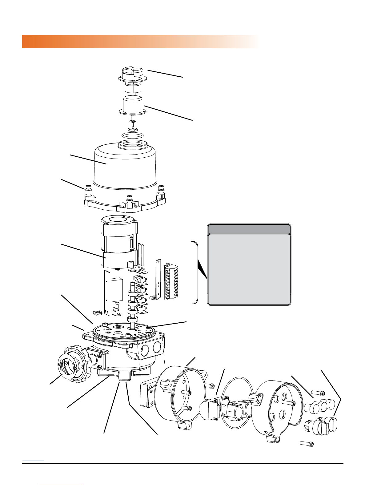
MECHANICAL DATA
Aluminum Casting
NEMA 4X Protection
Captured
Cover Screws
EXPLODED VIEW
HRCK2A~2S
UV / Impact resistant
protective Indicator Cover
Easily distinguishable
green/red
Position Indicator
Heavy Duty
Drive Motor
NEMA 4X
Cover Seal
Aluminum Casting
NEMA 4X Protection
Override Handwheel
version
Modular Control Cards including
3 position, proportional control,
Steel Cut Gearing
Cast Aluminum
Control Housing
Inside the actuator
internal heater, 2 position,
custom interfaces.
Removable Wiring Block
Easily accessible switch &
cam stacks
Switches
Power and
End of Travel
Indicators
Control knobs,
keys, or levers
8mm Bottom Mounted
Manual Override Shaft on
versions without Hand Wheel
ISO5211 Double Square
Female Drive Socket
Back to TOC
Hayward Flow Control
1-888-HAY-INDL (1-888-429-4635)
ISO5211 Mounting System
USE ONLY HAYWARD GENUINE REPLACEMENT PARTS
www.haywardowcontrol.com
HRSLCSSPLMNTIOM Rev A
Page 32 of 42
Page 33
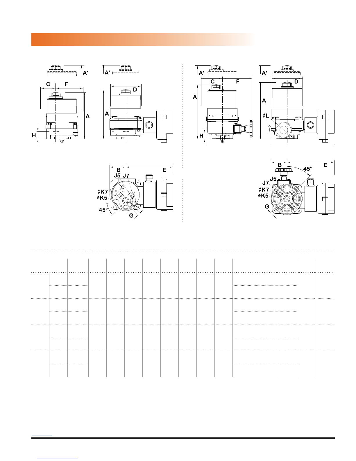
MECHANICAL DATA
DIMENSIONAL DATA
HRCK2A~2S
COVER REMOVAL
CLEARANCE
Note: Handwheel rotates CW to drive Output shaft CW
COVER REMOVAL
CLEARANCE
ON/OFF HEIGHT DIM MODULATING HEIGHT DIM ON/OFF HEIGHT DIM MODULATING HEIGHT DIM
COVER REMOVAL
CLEARANCE
HRSN2A/2R (NO HANDWHEEL) HRSN2B/2S (WITH HANDWHEEL OVERRIDE)
DIMENSIONS
MODEL
on/off - LV 6.38 / 162
HRCK2A
Mod - LV 7.56 / 192 (4) M8-1.25 X 20mm Deep
on/off - LV 7.40 / 188
HRCK2B
Mod - LV 8.58 / 218 (4) M8-1.25 X 20mm Deep
on/off - LV 6.38 / 162
HRCK2R
Mod - LV 7.56 / 192 (4) M8-1.25 X 20mm Deep
on/off - LV 7.40 / 188
HRCK2S
Mod - LV 8.58 / 218 (4) M8-1.25 X 20mm Deep
A
in/mm
A'
B
C
D
E
F
G*
H
in/mm
in/mm
in/mm
in/mm
in/mm
in/mm
in/mm
in/mm
4.93/125 2.20/56 1.40/36 4.22/107 6.63/170 3.25/83 0.551/14 0.78/20
4.93/125 2.20/56 2.32/59 4.22/107 6.63/170 4.25/108 0.551/14 0.78/20
4.93/125 2.20/56 1.40/36 4.22/107 6.63/170 3.25/83 0.551/14 0.78/20
4.93/125 2.20/56 2.32/59 4.22/107 6.63/170 4.25/108 0.669/17 0.78/20
J*
in/mm
(4) M6-1.0 X 18mm Deep
(4) M6-1.0 X 18mm Deep
(4) M6-1.0 X 18mm Deep
(4) M6-1.0 X 18mm Deep
K*
in/mm
F05 /
1.969/50
F07 /
2.756/70
F05 /
1.969/50
F07 /
2.756/70
F05 /
1.969/50
F07 /
2.756/70
F05 /
1.969/50
F07 /
2.756/70
L
in/mm
- 11.3/5.1
2.5/63
12 turns
90°
- 11.3/5.1
2.5/63
14 turns
90°
WEIGHT
lbs/kg
11.3/5.1
11.3/5.1
Back to TOC
Hayward Flow Control
1-888-HAY-INDL (1-888-429-4635)
USE ONLY HAYWARD GENUINE REPLACEMENT PARTS
www.haywardowcontrol.com
HRSLCSSPLMNTIOM Rev A
Page 33 of 42
Page 34
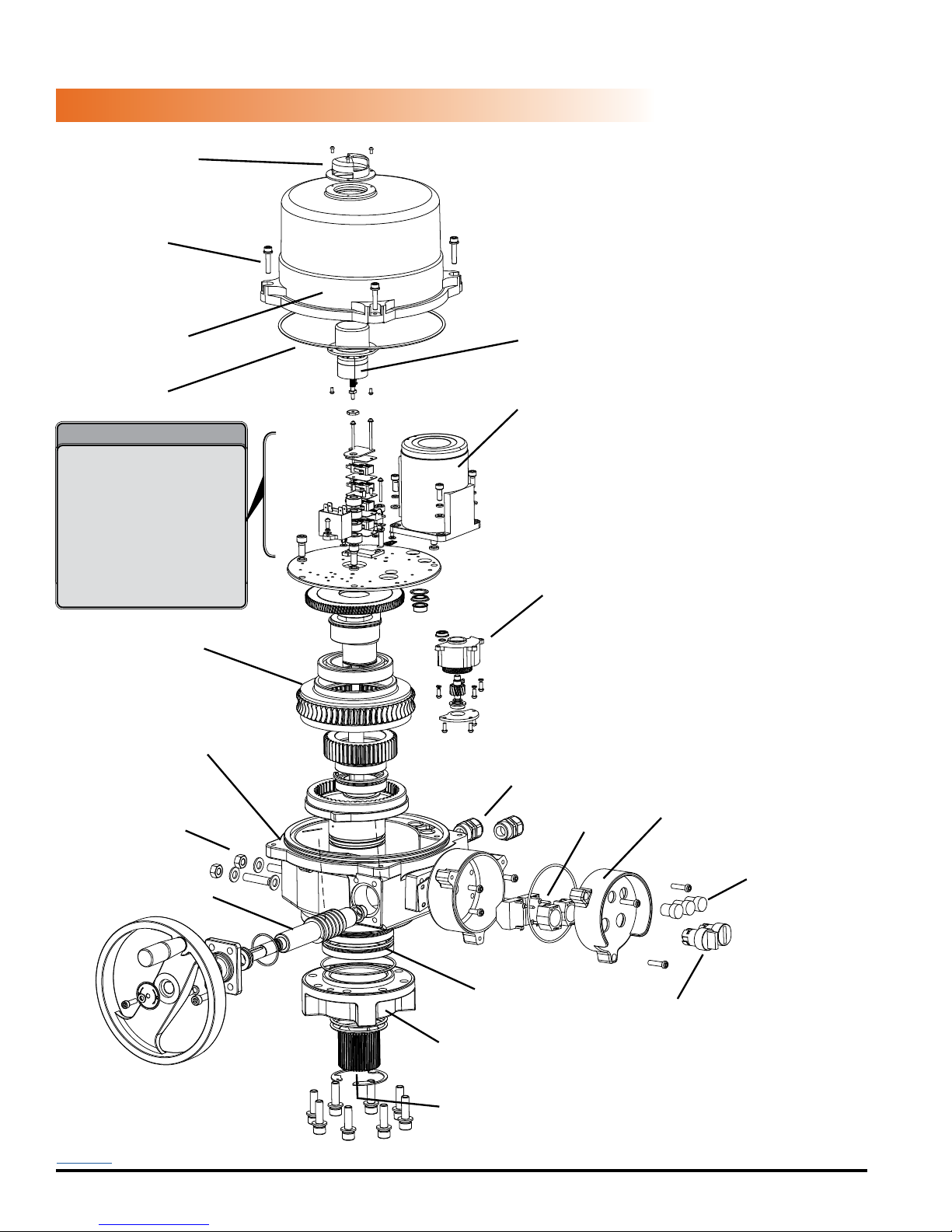
MECHANICAL DATA
UV / Impact resistant
protective Indicator Cover
Captured
Cover Screws
EXPLODED VIEW
HRCK, HRCP 3A~4F
Aluminum Casting
NEMA 4X Protection
NEMA 4X
Cover Seal
Inside the actuator
Modular Control Cards including
internal heater, 2 position,
3 position, proportional control,
custom interfaces.
Removable Wiring Block
Easily accessible switch &
cam stacks
Steel Cut Gearing
Aluminum Casting
NEMA 4X Protection
External
Mechanical Stop
Adjustments
Worm Override Shaft
Easily distinguishable
green/red
Position Indicator
Heavy Duty
Drive Motor
Torque Switch
NEMA 4X
Sealed Conduit Entry
(2) - 3/4”
Cast Aluminum
Control Housing
Control PCB
Power and
End of Travel
Indicators
Manual Override
Handwheel
Back to TOC
Hayward Flow Control
1-888-HAY-INDL (1-888-429-4635)
Main Shaft Ball Bearings
Changeable ISO5211
Mounting System
ISO5211 Double Square
Female Drive Socket
USE ONLY HAYWARD GENUINE REPLACEMENT PARTS
www.haywardowcontrol.com
Control knobs, keys,
or levers
HRSLCSSPLMNTIOM Rev A
Page 34 of 42
Page 35
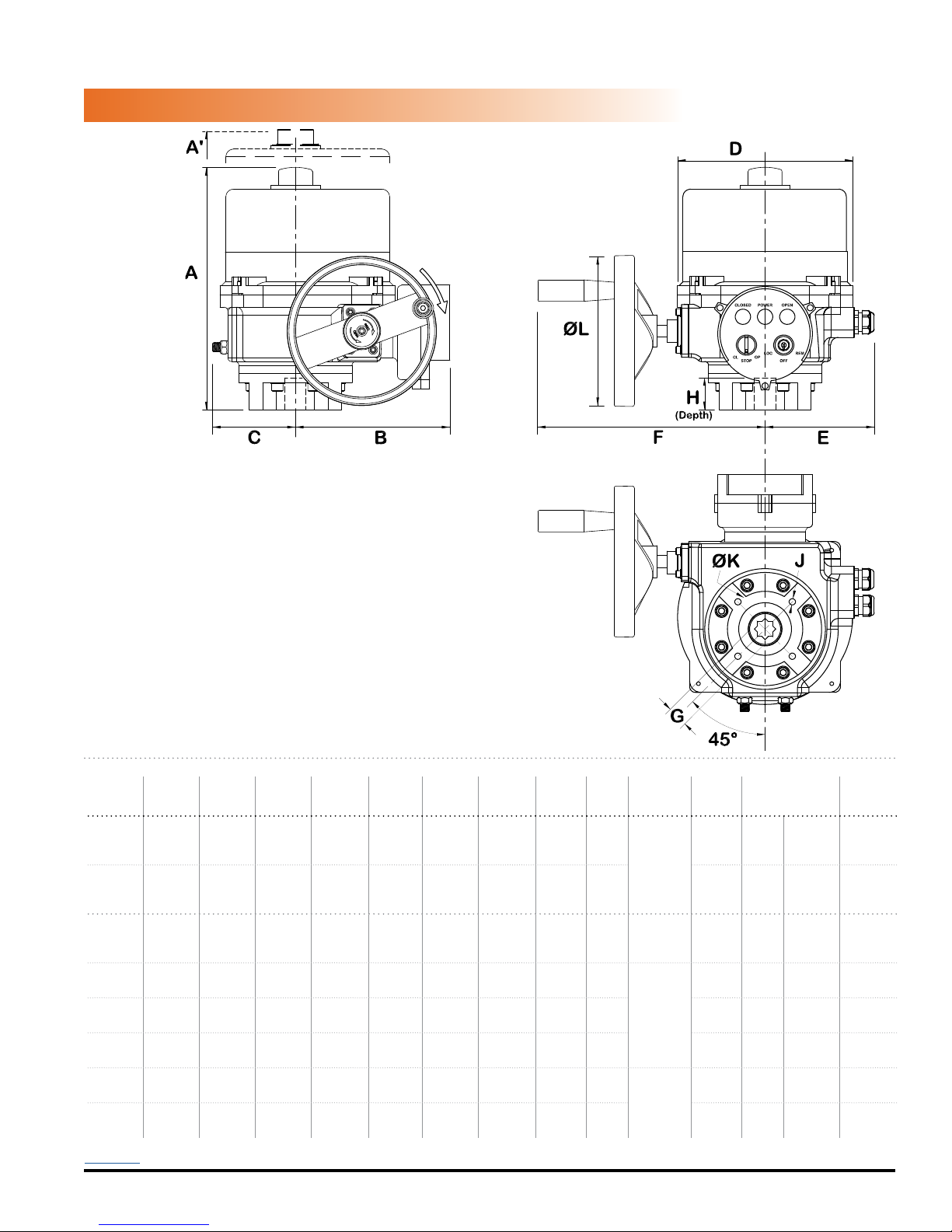
MECHANICAL DATA
COVER REMOVAL
CLEARANCE
DIMENSIONAL DATA
HRCK, HRCP 3A~4F
OUTPUT
SHAFT CW
DIMENSIONS
MODEL A
in/mm
A'
in/mm
B
in/mm
HRSN3A 10.45/265 6/150 7.35/187 3.11/79 8.50/216 4.73/120 9.45/240 0.669/17 1.38/35
HRSN3B 10.45/265 6/150 7.35/187 3.11/79 8.50/216 4.73/120 9.45/240 0.669/17 1.38/35
HRSN4A 12.64/321 7.87/200 8.78/223 4.06/103 10.31/262 5.91/150 11.69/297 0.866/22 2.17/55
HRSN4B 12.64/321 7.87/200 8.78/223 4.06/103 10.31/262 5.91/150 11.69/297 1.063/27 2.17/55
HRSN4C 12.64/321 7.87/200 8.78/223 4.06/103 10.31/262 5.91/150 11.69/297 1.063/27 2.17/55
HRSN4D 12.64/321 7.87/200 8.78/223 4.06/103 10.31/262 5.91/150 11.69/297 1.063/27 2.17/55
HRSN4E 14.88/378 9.84/250 9.49/241 4.69/119 11.54/293 6.34/161 13.62/346 1.063/27 2.56/65
HRSN4F 14.88/378 9.84/250 9.49/241 4.69/119 11.54/293 6.34/161 13.62/346 1.417/36 2.56/65
Back to TOC
Hayward Flow Control
1-888-HAY-INDL (1-888-429-4635)
C
in/mm
D
E
in/mm
USE ONLY HAYWARD GENUINE REPLACEMENT PARTS
in/mm
www.haywardowcontrol.com
F
in/mm
G*
in/mm
in/mm
H
J*
K*
in/mm
(4) M8
in/mm
F07
2.756/70
4.7/120
X 20mm
F07
2.756/70
F10
4.02/102
F12
4.92/125
F12
4.92/125
F12
4.92/125
F14
5.51/140
F14
5.51/140
4.7/120
7.76 /
197
7.76 /
197
7.76 /
197
7.76 /
197
11.42 /
290
11.42 /
290
Deep
(4) M10
-1.5 X
20mm D
(4) M12
-1.75 X
25mm D
(4) M16
-2.0 X
25mm D
*Consult Hayward Flow Control for optional ISO patterns
12.5
turns
WEIGHT
lbs/kg
26.5/12
L
90°
12.5
turns
26.5/12
90°
14.5 turns
90°
14.5 turns
90°
14.5 turns
90°
14.5 turns
90°
16 turns
90°
16 turns
90°
HRSLCSSPLMNTIOM Rev A
51/23
51/23
51/23
51/23
82/38
82/38
Page 35 of 42
Page 36
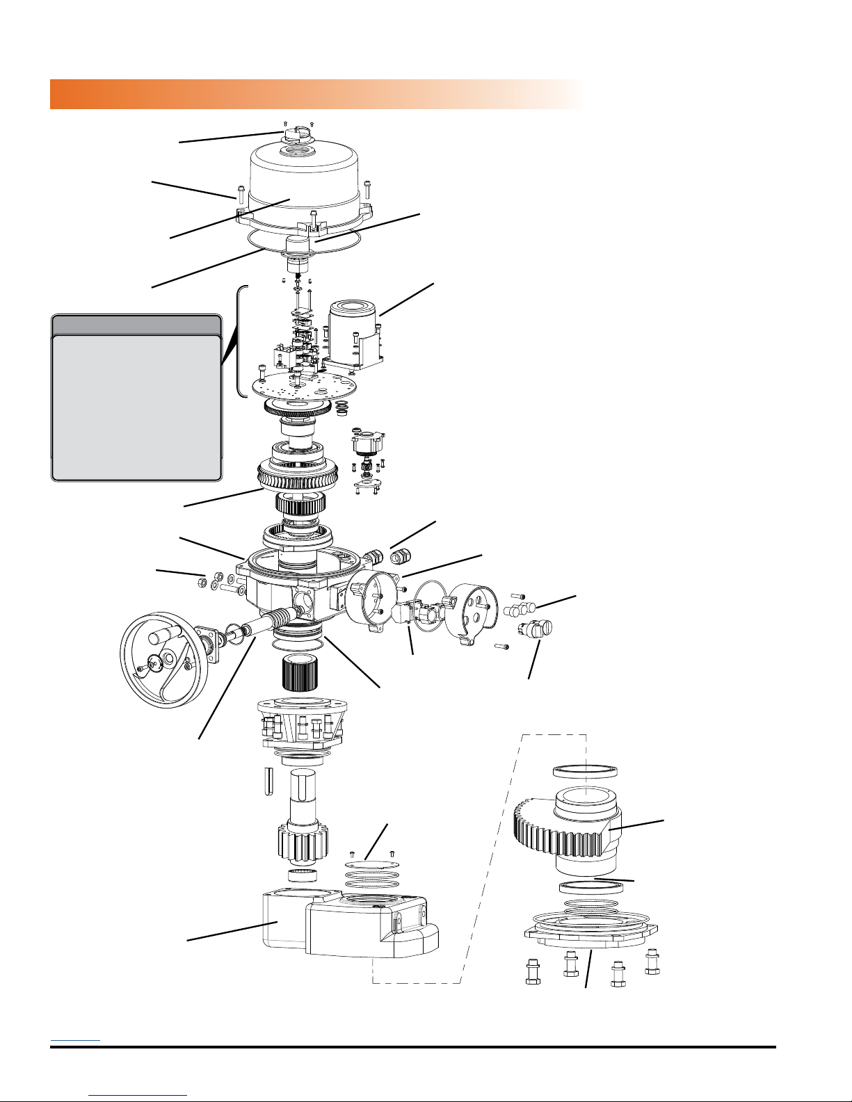
MECHANICAL DATA
UV / Impact resistant
protective Indicator Cover
Captured
Cover Screws
Aluminum Casting
NEMA 4X Protection
NEMA 4X
Cover Seal
Inside the actuator
Modular Control Cards including
internal heater, 2 position,
3 position, proportional control,
custom interfaces.
Removable Wiring Block
Easily accessible switch &
cam stacks
EXPLODED VIEW
HRCK, HRCP 5A~6A
Easily distinguishable
green/red
Position Indicator
Heavy Duty
Drive Motor
Torque
Switches
Steel Cut Gearing
Aluminum Casting
NEMA 4X Protection
External
Mechanical Stop
Adjustments
Manual Override
Handwheel
Worm Override Shaft
Sealed Conduit Entry
Control PCB
Main Shaft
Ball Bearings
Position Indicator
NEMA 4X
(2) - 3/4”
Cast Aluminum
Control Housing
Power and
End of Travel
Indicators
Control knobs, keys,
or levers
Steel Cut
Gearing
ISO5211 Double
Square Female
Drive Socket
Aluminum Casting
NEMA 4X Protection
Lower casting has
been rotated for clarity
Back to TOC
Hayward Flow Control
1-888-HAY-INDL (1-888-429-4635)
USE ONLY HAYWARD GENUINE REPLACEMENT PARTS
www.haywardowcontrol.com
ISO5211
Mounting System
HRSLCSSPLMNTIOM Rev A
Page 36 of 42
Page 37
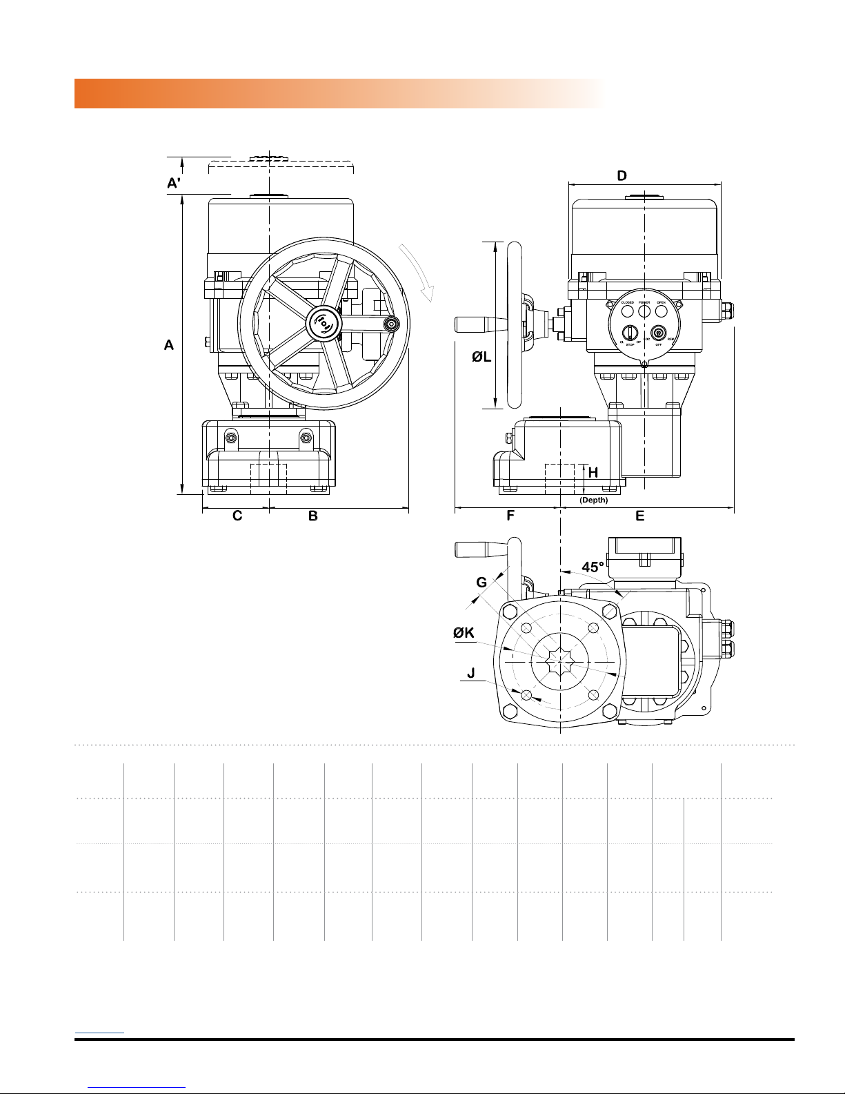
COVER REMOVAL
MECHANICAL DATA
CLEARANCE
COVER REMOVAL
CLEARANCE
DIMENSIONAL DATA
HRCK, HRCP 5A~6A
OUTPUT
SHAFT CW
DIMENSIONS
MODEL A
in/mm
A'
in/mm
B
in/mm
in/mm
HRSN5A 20.94/532 9.84/250 8.46/215 4.57/116 11.54/293 11.89/302 7.17/182 1.811/46 3.35/85
HRSN5B 20.94/532 9.84/250 8.46/215 4.57/116 11.54/293 11.89/302 7.17/182 1.811/46 3.35/85
HRSN6A 20.94/532 9.84/250 8.46/215 4.57/116 11.54/293 11.89/302 7.17/182 1.811/46 3.35/85
Back to TOC
Hayward Flow Control
1-888-HAY-INDL (1-888-429-4635)
C
D
E
in/mm
USE ONLY HAYWARD GENUINE REPLACEMENT PARTS
in/mm
www.haywardowcontrol.com
F
in/mm
G*
in/mm
H
J*
K*
in/mm
in/mm
(4) M20
- 2.5 X
35mm D
(4) M20
- 2.5 X
35mm D
(4) M20
- 2.5 X
35mm D
*Consult Hayward Flow Control for optional ISO patterns
in/mm
F16
6.50/165
F16
6.50/165
F16
6.50/165
L
11.42 /
290
11.42 /
290
11.42 /
290
WEIGHT
lbs/kg
36.5
167/76
turns
90°
36.5
167/76
turns
90°
36.5
167/76
turns
90°
HRSLCSSPLMNTIOM Rev A
Page 37 of 42
Page 38
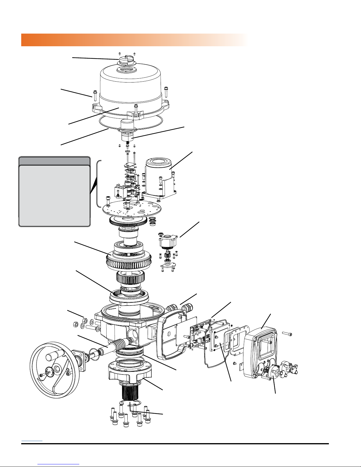
MECHANICAL DATA
UV / Impact resistant
protective Indicator Cover
Captured
Cover Screws
EXPLODED VIEW
HRCL, HRCD 3A~4F
Aluminum Casting
NEMA 4X Protection
NEMA 4X
Cover Seal
Inside the actuator
Modular Control Cards including
internal heater, 2 position,
3 position, proportional control,
custom interfaces.
Removable Wiring Block
Easily accessible switch &
cam stacks
Steel Cut Gearing
Aluminum Casting
NEMA 4X Protection
External
Mechanical Stop
Adjustments
Easily distinguishable
green/red
Position Indicator
Heavy Duty
Drive Motor
Torque Switch
NEMA 4X
Sealed Conduit Entry
(2) - 3/4”
Control PCB
Cast Aluminum
Control Housing
Worm Override Shaft
Manual Override
Handwheel
Back to TOC
Hayward Flow Control
1-888-HAY-INDL (1-888-429-4635)
Main Shaft Ball Bearings
Status, Position and
Changeable ISO5211
Mounting System
ISO5211 Double Square
Female Drive Socket
USE ONLY HAYWARD GENUINE REPLACEMENT PARTS
www.haywardowcontrol.com
Fault Display
Non-Intrusive
Magnetic Switches
HRSLCSSPLMNTIOM Rev A
Page 38 of 42
Page 39
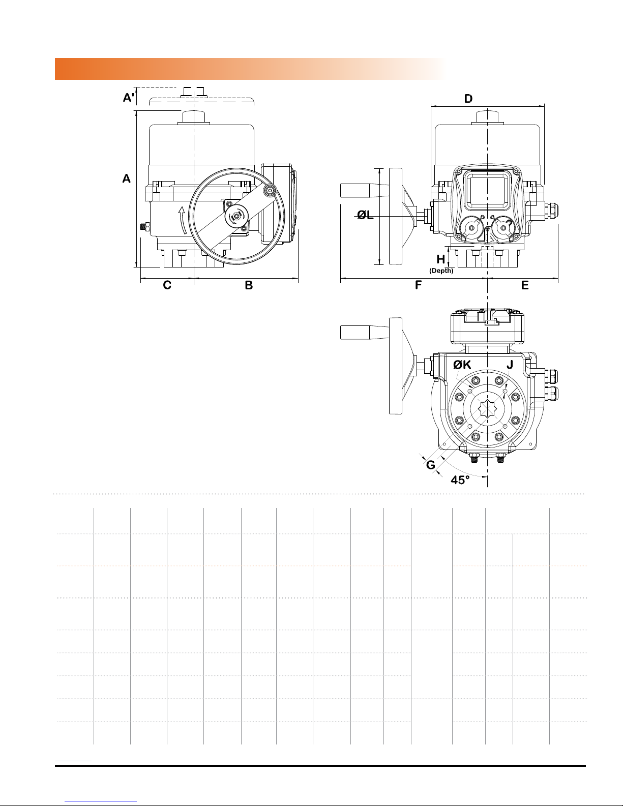
MECHANICAL DATA
COVER REMOVAL
CLEARANCE
DIMENSIONAL DATA
HRCL, HRCD 3A~4F
OUTPUT
SHAFT CW
DIMENSIONS
MODEL A
in/mm
A'
in/mm
B
in/mm
HRSN3A 10.45/265 6/150 7.35/187 3.11/79 8.50/216 4.73/120 9.45/240 0.669/17 1.38/35
HRSN3B 10.45/265 6/150 7.35/187 3.11/79 8.50/216 4.73/120 9.45/240 0.669/17 1.38/35
HRSN4A 12.64/321 7.87/200 8.78/223 4.06/103 10.31/262 5.91/150 11.69/297 0.866/22 2.17/55
HRSN4B 12.64/321 7.87/200 8.78/223 4.06/103 10.31/262 5.91/150 11.69/297 1.063/27 2.17/55
HRSN4C 12.64/321 7.87/200 8.78/223 4.06/103 10.31/262 5.91/150 11.69/297 1.063/27 2.17/55
HRSN4D 12.64/321 7.87/200 8.78/223 4.06/103 10.31/262 5.91/150 11.69/297 1.063/27 2.17/55
HRSN4E 14.88/378 9.84/250 9.49/241 4.69/119 11.54/293 6.34/161 13.62/346 1.063/27 2.56/65
HRSN4F 14.88/378 9.84/250 9.49/241 4.69/119 11.54/293 6.34/161 13.62/346 1.417/36 2.56/65
Back to TOC
Hayward Flow Control
1-888-HAY-INDL (1-888-429-4635)
C
in/mm
D
E
in/mm
USE ONLY HAYWARD GENUINE REPLACEMENT PARTS
in/mm
www.haywardowcontrol.com
F
in/mm
G*
in/mm
in/mm
H
J*
K*
in/mm
(4) M8
in/mm
F07
2.756/70
4.7/ 20
X 20mm
F07
2.756/70
F10
4.02/102
F12
4.92/125
F12
4.92/125
F12
4.92/125
F14
5.51/140
F14
5.51/140
4.7/120
7.76 /
197
7.76 /
197
7.76 /
197
7.76 /
197
11.42 /
290
11.42 /
290
Deep
(4) M10
-1.5 X
20mm D
(4) M12
-1.75 X
25mm D
(4) M16
-2.0 X
25mm D
*Consult Hayward Flow Control for optional ISO patterns
12.5
turns
WEIGHT
lbs/kg
26.5/12
L
90°
12.5
turns
26.5/12
90°
14.5 turns
90°
14.5 turns
90°
14.5 turns
90°
14.5 turns
90°
16 turns
90°
16 turns
90°
HRSLCSSPLMNTIOM Rev A
51/23
51/23
51/23
51/23
82/38
82/38
Page 39 of 42
Page 40
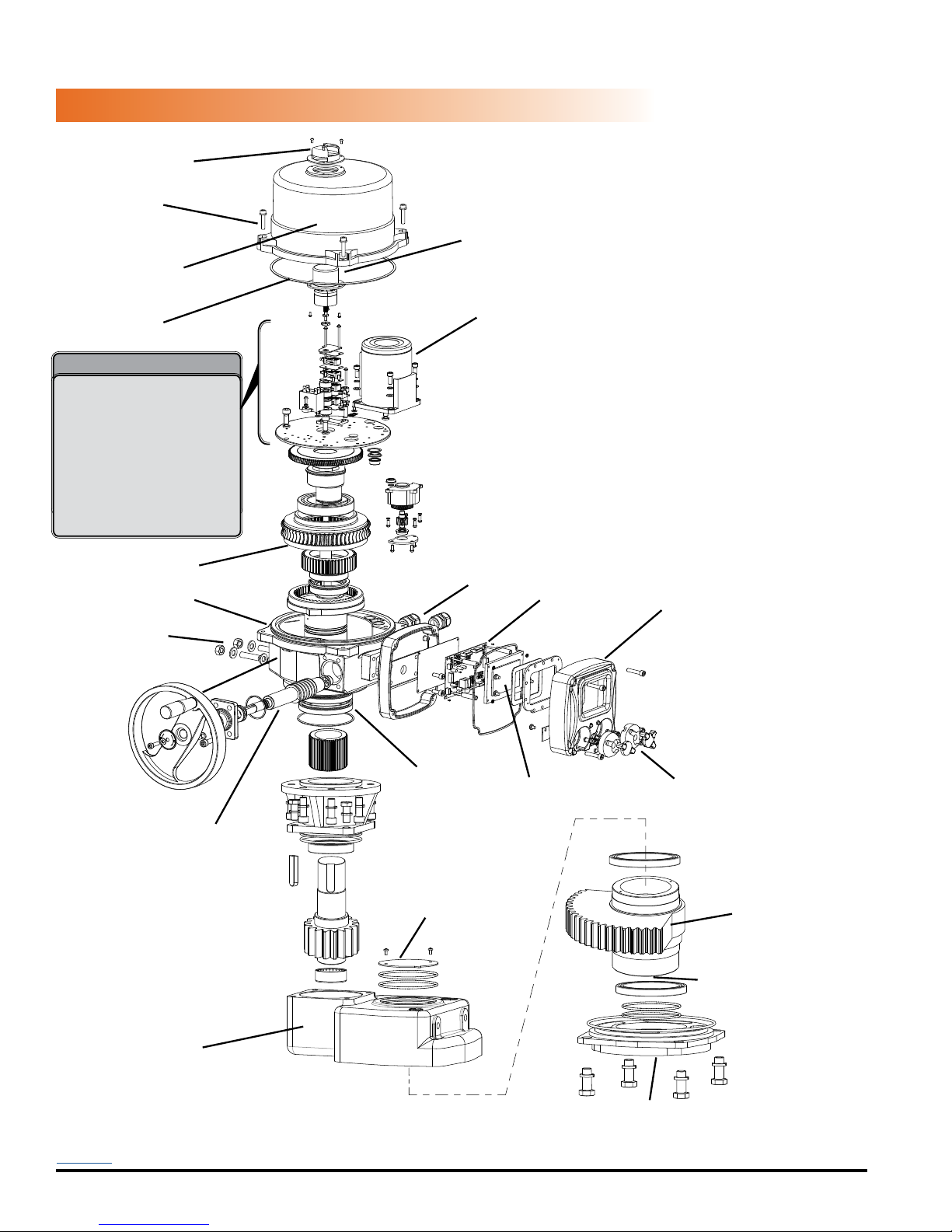
MECHANICAL DATA
UV / Impact resistant
protective Indicator Cover
Captured
Cover Screws
Aluminum Casting
NEMA 4X Protection
NEMA 4X
Cover Seal
Inside the actuator
Modular Control Cards including
internal heater, 2 position,
3 position, proportional control,
custom interfaces.
Removable Wiring Block
Easily accessible switch &
cam stacks
Steel Cut Gearing
Aluminum Casting
NEMA 4X Protection
Easily distinguishable
green/red
Position Indicator
Heavy Duty
Drive Motor
Torque
Switches
NEMA 4X
Sealed Conduit Entry
(2) - 3/4”
Control PCB
EXPLODED VIEW
HRCL, HRCD 5A~6A
Cast Aluminum
Control Housing
External
Mechanical Stop
Adjustments
Manual Override
Handwheel
Worm Override Shaft
Aluminum Casting
NEMA 4X Protection
Ball Bearings
Position Indicator
Lower casting has
been rotated for clarity
Main Shaft
Status, Position and
Fault Display
Non-Intrusive
Magnetic Switches
Steel Cut
Gearing
ISO5211 Double
Square Female
Drive Socket
ISO5211
Mounting System
Back to TOC
Hayward Flow Control
1-888-HAY-INDL (1-888-429-4635)
USE ONLY HAYWARD GENUINE REPLACEMENT PARTS
www.haywardowcontrol.com
HRSLCSSPLMNTIOM Rev A
Page 40 of 42
Page 41
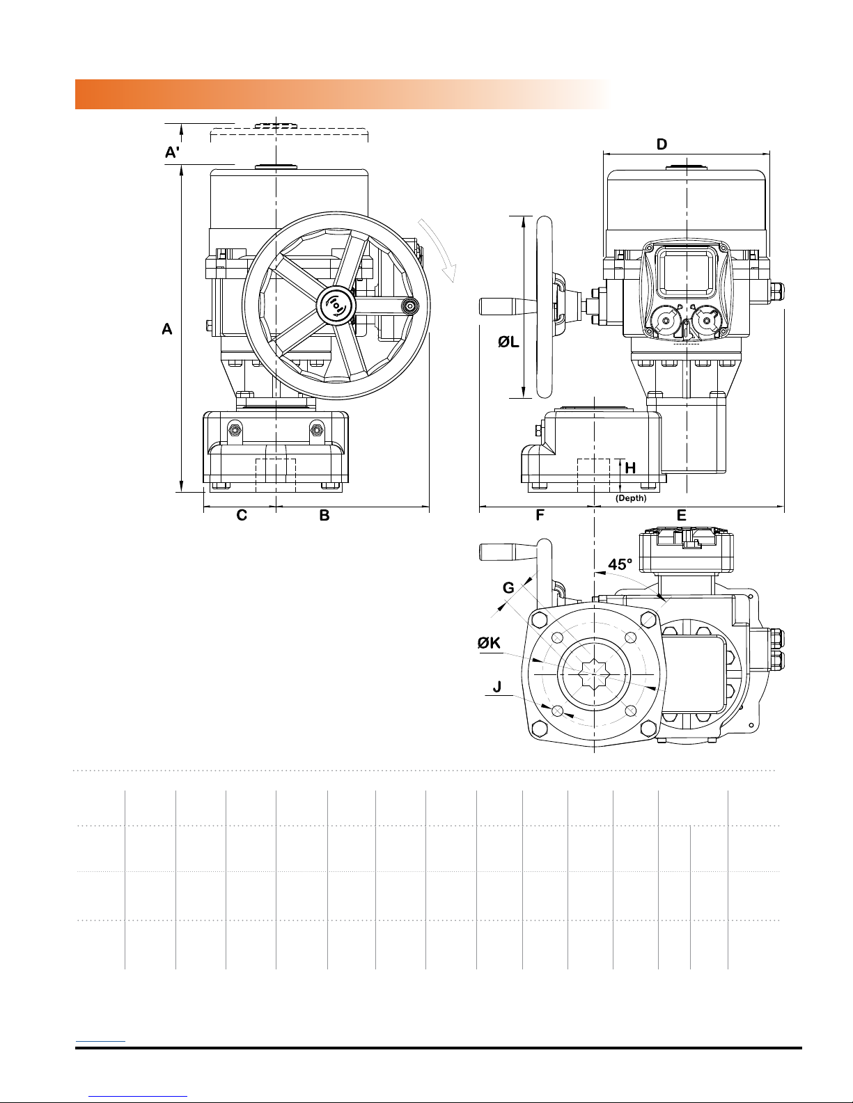
MECHANICAL DATA
COVER REMOVAL
CLEARANCE
DIMENSIONAL DATA
HRCL, HRCD 5A~6A
OUTPUT
SHAFT CW
DIMENSIONS
MODEL A
in/mm
A'
in/mm
B
in/mm
in/mm
HRSN5A 20.94/532 9.84/250 8.46/215 4.57/116 11.54/293 11.89/302 7.17/182 1.811/46 3.35/85
HRSN5B 20.94/532 9.84/250 8.46/215 4.57/116 11.54/293 11.89/302 7.17/182 1.811/46 3.35/85
HRSN6A 20.94/532 9.84/250 8.46/215 4.57/116 11.54/293 11.89/302 7.17/182 1.811/46 3.35/85
Back to TOC
Hayward Flow Control
1-888-HAY-INDL (1-888-429-4635)
C
D
E
in/mm
USE ONLY HAYWARD GENUINE REPLACEMENT PARTS
in/mm
www.haywardowcontrol.com
F
in/mm
G*
in/mm
H
J*
K*
in/mm
in/mm
(4) M20
- 2.5 X
35mm D
(4) M20
- 2.5 X
35mm D
(4) M20
- 2.5 X
35mm D
*Consult Hayward Flow Control for optional ISO patterns
in/mm
F16
6.50/165
F16
6.50/165
F16
6.50/165
L
11.42 /
290
11.42 /
290
11.42 /
290
WEIGHT
lbs/kg
36.5
167/76
turns
90°
36.5
167/76
turns
90°
36.5
167/76
turns
90°
HRSLCSSPLMNTIOM Rev A
Page 41 of 42
Page 42

This page intentionally left blank
Back to TOC
Hayward Flow Control
1-888-HAY-INDL (1-888-429-4635)
USE ONLY HAYWARD GENUINE REPLACEMENT PARTS
www.haywardowcontrol.com
HRSLCSSPLMNTIOM Rev A
Page 42 of 42
 Loading...